US4984628A - Apparatus for maintaining liquid temperature at a constant level - Google Patents
Apparatus for maintaining liquid temperature at a constant level Download PDFInfo
- Publication number
- US4984628A US4984628A US07/375,884 US37588489A US4984628A US 4984628 A US4984628 A US 4984628A US 37588489 A US37588489 A US 37588489A US 4984628 A US4984628 A US 4984628A
- Authority
- US
- United States
- Prior art keywords
- liquid
- cooling
- temperature
- heat exchange
- outlet port
- Prior art date
- Legal status (The legal status is an assumption and is not a legal conclusion. Google has not performed a legal analysis and makes no representation as to the accuracy of the status listed.)
- Expired - Lifetime
Links
Images


Classifications
-
- B—PERFORMING OPERATIONS; TRANSPORTING
- B01—PHYSICAL OR CHEMICAL PROCESSES OR APPARATUS IN GENERAL
- B01L—CHEMICAL OR PHYSICAL LABORATORY APPARATUS FOR GENERAL USE
- B01L7/00—Heating or cooling apparatus; Heat insulating devices
- B01L7/02—Water baths; Sand baths; Air baths
-
- G—PHYSICS
- G05—CONTROLLING; REGULATING
- G05D—SYSTEMS FOR CONTROLLING OR REGULATING NON-ELECTRIC VARIABLES
- G05D23/00—Control of temperature
- G05D23/19—Control of temperature characterised by the use of electric means
- G05D23/1919—Control of temperature characterised by the use of electric means characterised by the type of controller
-
- G—PHYSICS
- G05—CONTROLLING; REGULATING
- G05D—SYSTEMS FOR CONTROLLING OR REGULATING NON-ELECTRIC VARIABLES
- G05D23/00—Control of temperature
- G05D23/19—Control of temperature characterised by the use of electric means
- G05D23/20—Control of temperature characterised by the use of electric means with sensing elements having variation of electric or magnetic properties with change of temperature
Definitions
- the present invention relates to an apparatus for maintaining liquid temperature in a vessel at a constant level, and in particular, to an apparatus for maintaining liquid temperature in a reaction vessel of an automatic biochemical analyzer for clinic examination at a constant level.
- An automatic biochemical analyzer for clinic examination require a short rise time for the liquid temperature in the reaction vessel, i.e. a short time length from the start of the power supply to the time when a desired temperature of the liquid has been reached, and a precise control of the liquid temperature at a desired level, i.e. a control including only small temperature ripples.
- Automatic biochemical analyzers for clinical examination generally provide a cooling device which is continuously operated for cooling the liquid, and a heating device which is intermittently operated for heating the cooled liquid for maintaining the liquid temperature in a desired temperature range.
- the cooling device and the heating device are required to have a rather large capacity.
- the large capacities of the cooling and heating devices cause greater temperature ripples.
- smaller temperature ripples may be obtained by using cooling and heating devices each having a smaller capacity.
- this arrangement will cause a rather long rise time.
- the cooling device is operated to cool the liquid at all times, even when, at the start of the analyzer operation, the liquid temperature is lower than the desired value.
- the heating operation alone including no cooling operation is more effective to obtain a shorter rise time.
- the analyzer of the prior art has a demerit that an unnecessary cooling operation is carried out even in the case of the liquid having a lower initial temperature.
- the refrigerator of the cooling device is always applied on by a maximum load, which causes a shorter life of the refrigerator.
- An object of the present invention is to provide an apparatus for maintaining liquid temperature at a constant level, which can assure a shorter rise time of an automatic analyzer as well as small ripples of the liquid temperature.
- Another object of the present invention is to provide an apparatus for maintaining liquid temperature at a constant level, wherein the operation time of the refrigerator at a full load condition can be decreased.
- An apparatus for maintaining liquid temperature at a constant level comprises a reaction vessel for containing the liquid, cooling means for cooling the liquid and connected with the reaction vessel, heating means connected with the cooling means for heating the liquid cooled by the cooling means, circulating means for circulating the liquid through and among the reaction vessel, the cooling means and the heating means, temperature detecting means for detecting the temperature of the liquid heated by the heating means, heat exchange rate control means for controlling the heat exchange rate between the cooling means and the liquid, and control means for controlling the heating means and the heat exchange rate control means based on the control state of the apparatus and on the temperature difference between the detected temperature and a desired temperature.
- the heat exchange rate control means includes a plurality of cooling tubes disposed in the cooling means for passing the liquid therethrough each having a different heat exchange capacity, and valve means for opening or closing each of passages communicating with each of the cooling tubes.
- the heat exchange rate control means includes a cooling tube disposed in the cooling means and valve means for controlling the liquid flow directed towards the cooling tube.
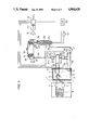
- FIG. 1 is a schematic representation of an embodiment of the apparatus for maintaining liquid temperature at a constant level according to the present invention with the heat exchange rate control means in an normal control state,
- FIG. 2 is a circuit diagram of the heat exchange rate control means shown in FIG. 1 in a starting state of the apparatus wherein the liquid temperature is lower than a desired temperature
- FIG. 3 is a circuit diagram of the heat exchange rate control means shown in FIG. 1 in a starting state of the apparatus wherein the liquid temperature is higher than a desired temperature
- FIG. 4 is a schematic representation of another embodiment of the apparatus according to the present invention.
- FIG. 1 shows the apparatus applied to an automatic biochemical analyzer for clinic examination.
- liquid 33 is contained in an annular cylindrical reaction vessel 27, which has an U-shaped axial cross-section and an upper opening.
- the reaction vessel 27 is connected at its bottom with an inlet port 28 and an outlet port 29 for circulating the liquid 33, and coated on its outer surface with insulation material 30.
- Numeral 31 denotes a cylindrical reaction cell, which is made of transparent material having a good optical feature and a high heat conductivity, such as glass, for example, and poured with a predetermined amount of analite and a predetermined amount of reagent to be mixed with each other.
- a plurality of reaction cells are supported by a reaction disk 32, and immersed at their lower portions into the temperature controlled liquid 33 in the reaction vessel 27 for maintaining the liquid in the reaction cells at a reaction temperature.
- the outlet 29 of reaction vessel 27 is connected with a pipe 38, which is connected with a first switching valve 34.
- the first switching valve 34 includes an inlet port, a first outlet port and a second outlet port and has two valve positions, i.e. a valve position 34a where the first outlet port is communicated with the inlet port, while the the second outlet port is closed, and a valve position 34b where the second outlet port is communicated with the inlet port, while the first outlet port is closed.
- the first outlet port of the first switching valve 34 is connected with one end of a first cooling tube 7 through a pipe 39, while the second outlet port is connected with an inlet port of a second switching valve 35 through a pipe 40.
- the second switching valve 35 includes, similarly to the first switching valve 34, an inlet port, a first outlet port and a second outlet port and has two valve positions, i.e. a valve position 35a where the first outlet port is communicated with the inlet port, while the the second outlet port is closed, and a valve position 35b where the second outlet port is communicated with the inlet port, while the first outlet port is closed.
- the first outlet port of the second switching valve 35 is connected with one end of a second cooling tube 8 through a pipe 43, while the second outlet port is connected through a pipe 44 with a pump 21 for circulating the liquid 33.
- the first switching valve 34 and the second switching valve 35 are controlled based on signals from control means 53, which will be described later.
- a cooling device 1 is a refrigerator using, for example, Freon gas as refrigerant, and includes a compressor 2, a condenser 3 for condensing the refrigerant, an expansion valve 4 for expanding the refrigerant, an evaporator 5 for evaporating the refrigerant and a cooling water tank 6 containing water 11.
- the outer surface of the cooling water tank 6 is coated with insulation material 9, and the upper opening of the tank is closed with a cover 10 made of insulation material.
- the water 11 in the cooling water tank 6 is cooled by utilizing evaporation heat of the refrigerant in the evaporator 5.
- the first cooling tube 7 extends in the cooling water tank 6 and then to outside of the tank 6 and is connected at the end, other than the one end of the tube 7, with the pipe 40 through a pipe 41.
- the second cooling tube 8 extends in the cooling water tank 6 and is then to outside of the tank 6 and connected at the end, other than the one end of the tube 8 with the pipe 44 through a pipe 45.
- the heat exchange capacity of the first cooling tube 7 is determined correspondingly to the maximum cooling capacity of the cooling device 1, while the heat exchange capacity of the second cooling tube 8 is so determined as to suit the normal control state of the apparatus.
- the discharge side of the pump 21 is connected through a pipe 36 with an inlet port 23 of a heating device 22, an outlet port 24 of which is connected with the inlet port 28 of the reaction vessel 27 through a pipe 37.
- the heating device 22 is of a cylindrical shape and includes therein a rod-shaped heater 25 and a temperature sensor 26 for detecting the liquid temperature Tp.
- the output signal of the temperature sensor 26 is transformed into an amplified voltage signal through an amplifier 51, and transferred to a A/D converter 52, where the signal is digitized, and then to the control means 53 which includes a micro-computer.
- the liquid temperature detecting actions of temperature sensor 26 are usually carried out every 20 msec.
- the electric power is supplied to the automatic biochemical analyzer for clinic examination, and a desired temperature value Ti is input into the control means 53.
- the desired temperature Ti is usually selected from among 25° C., 30° C. and 37° C.
- the control means 53 instructs to energize the heater 25 of the heating device 22, and to switch the first switching valve 34 and the second switching valve 35 to the position 34b and the position 35b, respectively (refer to FIG. 2).
- the liquid 33 in the reaction vessel 27 is flowed through the outlet port 29, the pipe 38, the inlet port of the first switching valve 34, the second outlet port of the first switching valve 34, the inlet port of the second switching valve 35, the second outlet port of the second switching valve 35 to the heating device 22, where the liquid is heated, and then is returned to the reaction vessel 27.
- the liquid 33 since the liquid 33 is not cooled by the cooling device 1, but only heated by the heater 25, the liquid 33 can be rapidly heated to the desired temperature Ti.
- the control means 53 instructs to deenergize the heater 25 of the heating device 22, and to switch the first switching valve 34 and the second switching valve 35 to the position 34a and the position 35b, respectively (refer to FIG. 3).
- the liquid 33 in the reaction vessel 27 is flowed through the outlet port 29, the pipe 38, the inlet port of the first switching valve 34, the first outlet port of the first switching valve 34, the first cooling tube 7, the pipe 41, the inlet port of the second switching valve 35, the second outlet port of the second switching valve 35 to the heating device 22, and then is returned to the reaction vessel 27.
- the liquid 33 since the liquid 33 is not heated by the heating device 22 because the heater 25 is deenergized, the liquid 33 can be rapidly cooled to the desired temperature Ti.
- the apparatus for maintaining the liquid temperature at a constant level is shifted to a normal control state (FIG. 1).
- the control means 53 instructs the first switching valve 34 and the second switching valve 35 to switch to the position 34b and the position 35a, respectively.
- the liquid 33 in the reaction vessel 27 is flowed through the outlet port 29, the pipe 38, the inlet port of the first switching valve 34, the second outlet port of the first switching valve 34, the pipe 40, the inlet port of the second switching valve 35, the first outlet port of the second switching valve 35, the pipe 43, the second cooling tube 8, and the pipe 45, to the heating device 22, where the liquid is suitably heated, and then is returned to the reaction vessel 27.
- the control means 53 controls the power supply to the heater 25 of the heating device 22 in on-off way based on temperature difference between the desired temperature Ti and the temperature Tp detected by the temperature sensor 26 every 20 mses. In this case, since the liquid 33 is cooled only by the second cooling tube 8 which has a smaller heat exchange capacity selected correspondingly to the normal temperature control state, a temperature control having a high precision and suppressed temperature ripples can be obtained.
- the cooling device 1 is required to run with full load only in a starting time of the analyzer operation, but with minimum load in an operation time of the normal temperature control state, the time duration of which is much longer than the starting time, the life of the cooling device becomes longer.
- FIG. 4 Another embodiment of the present invention is described below by referring to FIG. 4. Descriptions are shortened with respect to the portions identical with those of the embodiment shown in FIG. 1.
- a flow dividing valve 55 is instead arranged, and the second switching valve 35 and the second cooling tube 8 are both omitted.
- the flow dividing valve 55 includes an inlet port connected with the pipe 38, a first outlet port connected with one end of the first cooling tube 7, and a second outlet port connected with the pump 21 through a pipe 47, the other end of the first cooling tube 7 being connected with the pipe 47 through the pipe 41.
- the flow dividing valve 55 controls the flow rate of the liquid 33 into the first cooling tube 7 based on signals from the control means 53.
- the control means 53 instructs to energize the heater 25 of the heating device 22, and to control the flow dividing valve 55 so as to prevent the liquid 33 from flowing into the cooling tube 7.
- the liquid 33 in the reaction vessel 27 is flowed through the outlet port 29, the pipe 38, the flow dividing valve 55 and the pipe 47 to the heating device 22, where the liquid is heated, and then returned to the reaction vessel 27.
- the liquid 33 since the liquid 33 is not cooled by the cooling device 1, but only heated by the heater 25, the liquid 33 can be rapidly heated to the desired temperature Ti.
- the control means 53 instructs to deenergize the heater 25 of the heating device 22 and to control the flow dividing valve 55 so as to make the whole liquid 33 flow from the pipe 38 into the cooling tube 7.
- the liquid 33 in the reaction vessel 27 is flowed through the outlet port 29, the pipe 38, the flow dividing valve 55, the first cooling tube 7, where the liquid is cooled by the cooling water 11, to the heating device 22, and then returned to the reaction vessel 27.
- the liquid 33 since the liquid 33 is not heated by the heating device 22 because the heater 25 is deenergized, but cooled by the first cooling tube 7 having maximum cooling capacity, the liquid 33 can be rapidly cooled to the desired temperature Ti.
- the operation of the apparatus for maintaining the liquid temperature at a constant level is shifted to a normal control state.
- the control means 53 instructs the flow dividing valve 55 to divide the the liquid 33 and to control the flow rate to the first cooling tube 7 by an amount corresponding to the normal control state.
- a certain amount of the liquid 33 corresponding to the normal control state is cooled by the first cooling tube 7, and then joined with the liquid flow from the pipe 47.
- the joined liquid is then flowed to the heating device 22, where the liquid is suitably heated, and returned to the reaction vessel 27.
- the control means 53 controls the power supply to the heater 25 of the heating device 22 in on-off way based on the temperature difference between the desired temperature Ti and the liquid temperature Tp detected by the temperature sensor 26 every 20 msec. In this way, a temperature control having suppressed temperature ripples can be obtained.
Landscapes
- Physics & Mathematics (AREA)
- General Physics & Mathematics (AREA)
- Engineering & Computer Science (AREA)
- Automation & Control Theory (AREA)
- Health & Medical Sciences (AREA)
- Clinical Laboratory Science (AREA)
- Chemical & Material Sciences (AREA)
- Chemical Kinetics & Catalysis (AREA)
- Automatic Analysis And Handling Materials Therefor (AREA)
- Control Of Temperature (AREA)
- Physical Or Chemical Processes And Apparatus (AREA)
Applications Claiming Priority (2)
| Application Number | Priority Date | Filing Date | Title |
|---|---|---|---|
| JP63171652A JPH0731208B2 (ja) | 1988-07-09 | 1988-07-09 | 自動分析装置の反応温度制御装置 |
| JP63-171652 | 1988-07-09 |
Publications (1)
| Publication Number | Publication Date |
|---|---|
| US4984628A true US4984628A (en) | 1991-01-15 |
Family
ID=15927184
Family Applications (1)
| Application Number | Title | Priority Date | Filing Date |
|---|---|---|---|
| US07/375,884 Expired - Lifetime US4984628A (en) | 1988-07-09 | 1989-07-06 | Apparatus for maintaining liquid temperature at a constant level |
Country Status (3)
| Country | Link |
|---|---|
| US (1) | US4984628A (ja) |
| EP (1) | EP0350769A3 (ja) |
| JP (1) | JPH0731208B2 (ja) |
Cited By (28)
| Publication number | Priority date | Publication date | Assignee | Title |
|---|---|---|---|---|
| US5189960A (en) * | 1991-11-18 | 1993-03-02 | Fredric Valentini | Apparatus and method for controlling temperature of printing plate on cylinder in rotary press |
| US5211713A (en) * | 1990-11-30 | 1993-05-18 | Tabai Espec Corp. | Temperature control method with simultaneous heating and cooling near the set-point |
| US5247811A (en) * | 1990-11-15 | 1993-09-28 | Shimizu Construction Co., Ltd | Production and heat storage system for low-temperature chilled water |
| US5395451A (en) * | 1993-05-26 | 1995-03-07 | Schmidt-Bretten, Inc. | Paint temperature control system |
| US5413166A (en) * | 1993-05-07 | 1995-05-09 | Kerner; James M. | Thermoelectric power module |
| US5476137A (en) * | 1992-03-13 | 1995-12-19 | Toshiba Kikai Kabushiki Kaisha | Ultra-precision temperature control system for machine tool and control method therefor |
| US5515910A (en) * | 1993-05-03 | 1996-05-14 | Micro Control System | Apparatus for burn-in of high power semiconductor devices |
| US5598888A (en) * | 1994-09-23 | 1997-02-04 | Grumman Aerospace Corporation | Cryogenic temperature gradient microscopy chamber |
| US5692556A (en) * | 1994-01-14 | 1997-12-02 | Hafner; Erich | Precision temperature test chamber |
| US5795784A (en) | 1996-09-19 | 1998-08-18 | Abbott Laboratories | Method of performing a process for determining an item of interest in a sample |
| US5856194A (en) | 1996-09-19 | 1999-01-05 | Abbott Laboratories | Method for determination of item of interest in a sample |
| US6044903A (en) * | 1998-02-20 | 2000-04-04 | Frigid Units, Inc. | Water conditioning assembly |
| EP0967537A3 (en) * | 1994-01-21 | 2000-05-24 | FSI International, Inc. | Temperature control apparatus and method with recirculated coolant |
| US6148909A (en) * | 1998-01-27 | 2000-11-21 | Komatsu Ltd. | Temperature control device and temperature control method |
| US6389829B2 (en) * | 1999-11-30 | 2002-05-21 | Innotech Corporation | Temperature control system |
| US20030173351A1 (en) * | 2002-03-15 | 2003-09-18 | Boris Atlas | Semiconductor processing temperature control |
| US6749016B2 (en) * | 2002-01-14 | 2004-06-15 | Smc Kabushiki Kaisha | Brine temperature control apparatus using a three-way proportional valve |
| US20040247500A1 (en) * | 2001-09-04 | 2004-12-09 | Robert Ashe | Temperature control system |
| US7543455B1 (en) * | 2008-06-06 | 2009-06-09 | Chengjun Julian Chen | Solar-powered refrigerator using a mixture of glycerin, alcohol and water to store energy |
| US20100206543A1 (en) * | 2009-02-13 | 2010-08-19 | Tylisz Brian M | Two-stage heat exchanger with interstage bypass |
| US20110107789A1 (en) * | 2008-04-01 | 2011-05-12 | Holger Sedlak | Liquefier for a Heat Pump and Heat Pump |
| US20110223063A1 (en) * | 2010-03-12 | 2011-09-15 | Katsumi Hironori | Sample analyzer and non-transitory storage medium |
| US20110277983A1 (en) * | 2010-05-13 | 2011-11-17 | Kelk Ltd. | Temperature controller, fluid circulator and temperature control method using temperature controller |
| CN102430979A (zh) * | 2011-10-13 | 2012-05-02 | 清华大学 | 抛光液温度控制装置和抛光液输送设备 |
| CN101219403B (zh) * | 2007-10-17 | 2012-06-20 | 上海电力学院 | 液冷降温式恒温槽系统及智能控温方法 |
| US20150144300A1 (en) * | 2013-11-22 | 2015-05-28 | Thermo Fisher Scientific (Asheville) Llc | Recirculating Bath With Global Voltage Compatibility |
| CN109073666A (zh) * | 2016-07-14 | 2018-12-21 | 株式会社日立高新技术 | 自动分析装置 |
| US10222312B2 (en) * | 2016-06-28 | 2019-03-05 | Anton Paar Quantatec, Inc. | Cryogenic temperature controller for volumetric sorption analyzers |
Families Citing this family (9)
| Publication number | Priority date | Publication date | Assignee | Title |
|---|---|---|---|---|
| JP2008075920A (ja) * | 2006-09-20 | 2008-04-03 | Apisute:Kk | チラー装置 |
| CN102305851B (zh) * | 2011-07-26 | 2014-03-26 | 珠海森龙生物科技有限公司 | 一种生化分析仪的恒温系统 |
| CN105080630B (zh) * | 2014-04-15 | 2017-09-15 | 中国石油化工股份有限公司 | 岩心夹持器的恒温系统及其实验方法 |
| CN106952749B (zh) * | 2017-04-28 | 2018-09-28 | 南通南铭电子有限公司 | 电容器引出线化成液温度控制装置及其温度控制方法 |
| CN110031378A (zh) * | 2019-05-16 | 2019-07-19 | 贵州大学 | 一种煤层注二氧化碳测试渗透率装置 |
| CN110756243A (zh) * | 2019-11-26 | 2020-02-07 | 深圳大学 | 恒温控温水浴装置及用途 |
| JP7369057B2 (ja) * | 2020-02-13 | 2023-10-25 | 株式会社日立ハイテク | 自動分析装置 |
| CN111729703A (zh) * | 2020-07-07 | 2020-10-02 | 山西钢科碳材料有限公司 | 恒温水浴装置 |
| CN112269413B (zh) * | 2020-11-10 | 2022-08-19 | 上海宇航系统工程研究所 | 一种便携式激光散热装置的控制方法 |
Citations (10)
| Publication number | Priority date | Publication date | Assignee | Title |
|---|---|---|---|---|
| US3047274A (en) * | 1959-02-18 | 1962-07-31 | Warren M Wilson | Variable area heat exchanger |
| US3227207A (en) * | 1963-03-04 | 1966-01-04 | Alan L Litman | Thermal environmental control apparatus |
| US3229754A (en) * | 1963-03-14 | 1966-01-18 | Phillips Petroleum Co | Heating and cooling temperature control system |
| US3370454A (en) * | 1965-11-24 | 1968-02-27 | Tenney Engineering Inc | Constant temperature bath for calibrating immersion type instruments |
| US4072181A (en) * | 1975-10-24 | 1978-02-07 | Vihorlat, Narodny Podnik | Apparatus for regulating the temperature of a casting mold |
| US4483823A (en) * | 1981-09-04 | 1984-11-20 | Hitachi, Ltd. | Chemical analyzer equipped with reagent cold-storage chamber |
| US4526012A (en) * | 1982-09-29 | 1985-07-02 | Kanto Seiki Kabushiki Kaisha | Liquid temperature regulator |
| US4729424A (en) * | 1985-04-05 | 1988-03-08 | Nec Corporation | Cooling system for electronic equipment |
| US4784213A (en) * | 1986-04-08 | 1988-11-15 | Temptronic Corporation | Mixing valve air source |
| US4798242A (en) * | 1985-05-30 | 1989-01-17 | Aisin Seiki Kabushiki Kaisha Co., Ltd. | Heat exchanger for recovering heat from exhaust gases |
Family Cites Families (6)
| Publication number | Priority date | Publication date | Assignee | Title |
|---|---|---|---|---|
| DE1126428B (de) * | 1960-02-05 | 1962-03-29 | Dr Med Kurt Sokol | Vorrichtung zum Einfrieren von Sperma, insbesondere Bullensperma |
| CH651392A5 (de) * | 1980-06-10 | 1985-09-13 | Ciba Geigy Ag | Waermeflusskalorimeter. |
| JPS60176172U (ja) * | 1984-04-28 | 1985-11-21 | オリンパス光学工業株式会社 | 恒温装置 |
| JPS6110559U (ja) * | 1984-06-26 | 1986-01-22 | 株式会社島津製作所 | 自動化学分析装置 |
| EP0175882A1 (de) * | 1984-09-07 | 1986-04-02 | Contraves Ag | Temperiervorrichtung zu einem Laborreaktor |
| GB2179128A (en) * | 1985-06-18 | 1987-02-25 | Paxman Briston Coolers Ltd | Apparatus for cooling liquids |
-
1988
- 1988-07-09 JP JP63171652A patent/JPH0731208B2/ja not_active Expired - Lifetime
-
1989
- 1989-07-04 EP EP19890112191 patent/EP0350769A3/en not_active Withdrawn
- 1989-07-06 US US07/375,884 patent/US4984628A/en not_active Expired - Lifetime
Patent Citations (10)
| Publication number | Priority date | Publication date | Assignee | Title |
|---|---|---|---|---|
| US3047274A (en) * | 1959-02-18 | 1962-07-31 | Warren M Wilson | Variable area heat exchanger |
| US3227207A (en) * | 1963-03-04 | 1966-01-04 | Alan L Litman | Thermal environmental control apparatus |
| US3229754A (en) * | 1963-03-14 | 1966-01-18 | Phillips Petroleum Co | Heating and cooling temperature control system |
| US3370454A (en) * | 1965-11-24 | 1968-02-27 | Tenney Engineering Inc | Constant temperature bath for calibrating immersion type instruments |
| US4072181A (en) * | 1975-10-24 | 1978-02-07 | Vihorlat, Narodny Podnik | Apparatus for regulating the temperature of a casting mold |
| US4483823A (en) * | 1981-09-04 | 1984-11-20 | Hitachi, Ltd. | Chemical analyzer equipped with reagent cold-storage chamber |
| US4526012A (en) * | 1982-09-29 | 1985-07-02 | Kanto Seiki Kabushiki Kaisha | Liquid temperature regulator |
| US4729424A (en) * | 1985-04-05 | 1988-03-08 | Nec Corporation | Cooling system for electronic equipment |
| US4798242A (en) * | 1985-05-30 | 1989-01-17 | Aisin Seiki Kabushiki Kaisha Co., Ltd. | Heat exchanger for recovering heat from exhaust gases |
| US4784213A (en) * | 1986-04-08 | 1988-11-15 | Temptronic Corporation | Mixing valve air source |
Cited By (40)
| Publication number | Priority date | Publication date | Assignee | Title |
|---|---|---|---|---|
| US5247811A (en) * | 1990-11-15 | 1993-09-28 | Shimizu Construction Co., Ltd | Production and heat storage system for low-temperature chilled water |
| US5211713A (en) * | 1990-11-30 | 1993-05-18 | Tabai Espec Corp. | Temperature control method with simultaneous heating and cooling near the set-point |
| US5189960A (en) * | 1991-11-18 | 1993-03-02 | Fredric Valentini | Apparatus and method for controlling temperature of printing plate on cylinder in rotary press |
| US5476137A (en) * | 1992-03-13 | 1995-12-19 | Toshiba Kikai Kabushiki Kaisha | Ultra-precision temperature control system for machine tool and control method therefor |
| US5515910A (en) * | 1993-05-03 | 1996-05-14 | Micro Control System | Apparatus for burn-in of high power semiconductor devices |
| US5579826A (en) * | 1993-05-03 | 1996-12-03 | Micro Control Company | Method for burn-in of high power semiconductor devices |
| US5413166A (en) * | 1993-05-07 | 1995-05-09 | Kerner; James M. | Thermoelectric power module |
| US5395451A (en) * | 1993-05-26 | 1995-03-07 | Schmidt-Bretten, Inc. | Paint temperature control system |
| US5692556A (en) * | 1994-01-14 | 1997-12-02 | Hafner; Erich | Precision temperature test chamber |
| US6308776B1 (en) | 1994-01-21 | 2001-10-30 | Fsi International, Inc. | Temperature control apparatus with recirculated coolant |
| EP0967537A3 (en) * | 1994-01-21 | 2000-05-24 | FSI International, Inc. | Temperature control apparatus and method with recirculated coolant |
| US6854514B2 (en) | 1994-01-21 | 2005-02-15 | Fsi International, Inc. | Temperature control apparatus and method with recirculated coolant |
| US5598888A (en) * | 1994-09-23 | 1997-02-04 | Grumman Aerospace Corporation | Cryogenic temperature gradient microscopy chamber |
| US5856194A (en) | 1996-09-19 | 1999-01-05 | Abbott Laboratories | Method for determination of item of interest in a sample |
| US5795784A (en) | 1996-09-19 | 1998-08-18 | Abbott Laboratories | Method of performing a process for determining an item of interest in a sample |
| US6562298B1 (en) | 1996-09-19 | 2003-05-13 | Abbott Laboratories | Structure for determination of item of interest in a sample |
| US6148909A (en) * | 1998-01-27 | 2000-11-21 | Komatsu Ltd. | Temperature control device and temperature control method |
| US6044903A (en) * | 1998-02-20 | 2000-04-04 | Frigid Units, Inc. | Water conditioning assembly |
| US6389829B2 (en) * | 1999-11-30 | 2002-05-21 | Innotech Corporation | Temperature control system |
| US7767156B2 (en) | 2001-09-04 | 2010-08-03 | Ashe Morris Ltd | Temperature control system |
| US20040247500A1 (en) * | 2001-09-04 | 2004-12-09 | Robert Ashe | Temperature control system |
| US20080173439A1 (en) * | 2001-09-04 | 2008-07-24 | Ashe Morris Ltd | Temperature control system |
| US6749016B2 (en) * | 2002-01-14 | 2004-06-15 | Smc Kabushiki Kaisha | Brine temperature control apparatus using a three-way proportional valve |
| US6822202B2 (en) * | 2002-03-15 | 2004-11-23 | Oriol, Inc. | Semiconductor processing temperature control |
| US20050082278A1 (en) * | 2002-03-15 | 2005-04-21 | Boris Atlas | Semiconductor processing temperature control |
| US20030173351A1 (en) * | 2002-03-15 | 2003-09-18 | Boris Atlas | Semiconductor processing temperature control |
| US7180036B2 (en) | 2002-03-15 | 2007-02-20 | Oriol, Inc. | Semiconductor processing temperature control |
| CN101219403B (zh) * | 2007-10-17 | 2012-06-20 | 上海电力学院 | 液冷降温式恒温槽系统及智能控温方法 |
| US9709305B2 (en) | 2008-04-01 | 2017-07-18 | Efficient Energy Gmbh | Liquefier for a heat pump and heat pump |
| US20110107789A1 (en) * | 2008-04-01 | 2011-05-12 | Holger Sedlak | Liquefier for a Heat Pump and Heat Pump |
| US8978408B2 (en) * | 2008-04-01 | 2015-03-17 | Efficient Energy Gmbh | Liquefier for a heat pump and heat pump |
| US7543455B1 (en) * | 2008-06-06 | 2009-06-09 | Chengjun Julian Chen | Solar-powered refrigerator using a mixture of glycerin, alcohol and water to store energy |
| US20100206543A1 (en) * | 2009-02-13 | 2010-08-19 | Tylisz Brian M | Two-stage heat exchanger with interstage bypass |
| US20110223063A1 (en) * | 2010-03-12 | 2011-09-15 | Katsumi Hironori | Sample analyzer and non-transitory storage medium |
| US8834791B2 (en) * | 2010-03-12 | 2014-09-16 | Sysmex Corporation | Sample analyzer and non-transitory storage medium |
| US20110277983A1 (en) * | 2010-05-13 | 2011-11-17 | Kelk Ltd. | Temperature controller, fluid circulator and temperature control method using temperature controller |
| CN102430979A (zh) * | 2011-10-13 | 2012-05-02 | 清华大学 | 抛光液温度控制装置和抛光液输送设备 |
| US20150144300A1 (en) * | 2013-11-22 | 2015-05-28 | Thermo Fisher Scientific (Asheville) Llc | Recirculating Bath With Global Voltage Compatibility |
| US10222312B2 (en) * | 2016-06-28 | 2019-03-05 | Anton Paar Quantatec, Inc. | Cryogenic temperature controller for volumetric sorption analyzers |
| CN109073666A (zh) * | 2016-07-14 | 2018-12-21 | 株式会社日立高新技术 | 自动分析装置 |
Also Published As
| Publication number | Publication date |
|---|---|
| JPH0731208B2 (ja) | 1995-04-10 |
| EP0350769A3 (en) | 1991-01-30 |
| EP0350769A2 (en) | 1990-01-17 |
| JPH0221264A (ja) | 1990-01-24 |
Similar Documents
| Publication | Publication Date | Title |
|---|---|---|
| EP0350769A2 (en) | Apparatus for maintaining liquid temperature at a constant level | |
| KR900008514B1 (ko) | 공기 조화기 | |
| US6233955B1 (en) | Isothermal coolant circulating apparatus | |
| US5123477A (en) | Thermal reactor for biotechnological processes | |
| KR100340455B1 (ko) | 항온냉각액 순환장치 | |
| US4526012A (en) | Liquid temperature regulator | |
| US20030014988A1 (en) | Constant-temperature liquid circulating apparatus | |
| KR850007688A (ko) | 냉난방 급탕용(給湯用)히이트펌프 장치 | |
| JPH0581921B2 (ja) | ||
| US4894998A (en) | Absorption system hot and cold water supply apparatus | |
| JP3267187B2 (ja) | ヒートポンプ給湯機 | |
| US3227207A (en) | Thermal environmental control apparatus | |
| CN112856852A (zh) | 多通道恒温装置及其控制方法 | |
| JP2010142196A (ja) | 細胞培養装置及び細胞培養カセット | |
| US20070183945A1 (en) | Method and apparatus for controlling reaction temperature in bio-chemical instruments | |
| KR0152641B1 (ko) | Ptc 히터를 갖는 냉온수기와 그 동작제어방법 | |
| JPH0527674U (ja) | 反応槽循環水流量調整装置 | |
| US3029354A (en) | Level control and indicating mechanism | |
| SE515139C2 (sv) | Klimattestkammarsystem och sätt för driften därav | |
| JPH05264156A (ja) | 自動分析装置用試薬保冷庫 | |
| JP7664106B2 (ja) | 自動分析装置 | |
| RU2099773C1 (ru) | Устройство для регулирования температуры объекта | |
| KR870008161A (ko) | 냉방시스템의 용량제어 시스템 및 용량제어방법 | |
| JPH0623766B2 (ja) | 自動分析装置 | |
| SU1067483A1 (ru) | Термокриостат |
Legal Events
| Date | Code | Title | Description |
|---|---|---|---|
| AS | Assignment |
Owner name: HITACHI, LTD., JAPAN Free format text: ASSIGNMENT OF ASSIGNORS INTEREST.;ASSIGNORS:UCHIDA, HIROYASU;ABE, TETSUAKI;ISHIZAWA, HIROAKI;REEL/FRAME:005136/0268 Effective date: 19890623 |
|
| STCF | Information on status: patent grant |
Free format text: PATENTED CASE |
|
| FEPP | Fee payment procedure |
Free format text: PAYOR NUMBER ASSIGNED (ORIGINAL EVENT CODE: ASPN); ENTITY STATUS OF PATENT OWNER: LARGE ENTITY |
|
| FPAY | Fee payment |
Year of fee payment: 4 |
|
| FPAY | Fee payment |
Year of fee payment: 8 |
|
| FPAY | Fee payment |
Year of fee payment: 12 |