US4990076A - Pressure control apparatus and method - Google Patents
Pressure control apparatus and method Download PDFInfo
- Publication number
- US4990076A US4990076A US07/359,809 US35980989A US4990076A US 4990076 A US4990076 A US 4990076A US 35980989 A US35980989 A US 35980989A US 4990076 A US4990076 A US 4990076A
- Authority
- US
- United States
- Prior art keywords
- valve
- signal
- piston
- limit position
- electrical signal
- Prior art date
- Legal status (The legal status is an assumption and is not a legal conclusion. Google has not performed a legal analysis and makes no representation as to the accuracy of the status listed.)
- Expired - Lifetime
Links
Images



Classifications
-
- B—PERFORMING OPERATIONS; TRANSPORTING
- B01—PHYSICAL OR CHEMICAL PROCESSES OR APPARATUS IN GENERAL
- B01J—CHEMICAL OR PHYSICAL PROCESSES, e.g. CATALYSIS OR COLLOID CHEMISTRY; THEIR RELEVANT APPARATUS
- B01J3/00—Processes of utilising sub-atmospheric or super-atmospheric pressure to effect chemical or physical change of matter; Apparatus therefor
- B01J3/04—Pressure vessels, e.g. autoclaves
-
- B—PERFORMING OPERATIONS; TRANSPORTING
- B01—PHYSICAL OR CHEMICAL PROCESSES OR APPARATUS IN GENERAL
- B01J—CHEMICAL OR PHYSICAL PROCESSES, e.g. CATALYSIS OR COLLOID CHEMISTRY; THEIR RELEVANT APPARATUS
- B01J3/00—Processes of utilising sub-atmospheric or super-atmospheric pressure to effect chemical or physical change of matter; Apparatus therefor
- B01J3/002—Component parts of these vessels not mentioned in B01J3/004, B01J3/006, B01J3/02 - B01J3/08; Measures taken in conjunction with the process to be carried out, e.g. safety measures
-
- G—PHYSICS
- G01—MEASURING; TESTING
- G01N—INVESTIGATING OR ANALYSING MATERIALS BY DETERMINING THEIR CHEMICAL OR PHYSICAL PROPERTIES
- G01N3/00—Investigating strength properties of solid materials by application of mechanical stress
- G01N3/08—Investigating strength properties of solid materials by application of mechanical stress by applying steady tensile or compressive forces
- G01N3/10—Investigating strength properties of solid materials by application of mechanical stress by applying steady tensile or compressive forces generated by pneumatic or hydraulic pressure
- G01N3/12—Pressure testing
-
- G—PHYSICS
- G05—CONTROLLING; REGULATING
- G05D—SYSTEMS FOR CONTROLLING OR REGULATING NON-ELECTRIC VARIABLES
- G05D16/00—Control of fluid pressure
- G05D16/20—Control of fluid pressure characterised by the use of electric means
- G05D16/2006—Control of fluid pressure characterised by the use of electric means with direct action of electric energy on controlling means
- G05D16/208—Control of fluid pressure characterised by the use of electric means with direct action of electric energy on controlling means using a combination of controlling means as defined in G05D16/2013 and G05D16/2066
-
- B—PERFORMING OPERATIONS; TRANSPORTING
- B01—PHYSICAL OR CHEMICAL PROCESSES OR APPARATUS IN GENERAL
- B01J—CHEMICAL OR PHYSICAL PROCESSES, e.g. CATALYSIS OR COLLOID CHEMISTRY; THEIR RELEVANT APPARATUS
- B01J2219/00—Chemical, physical or physico-chemical processes in general; Their relevant apparatus
- B01J2219/00002—Chemical plants
- B01J2219/00027—Process aspects
- B01J2219/00038—Processes in parallel
-
- B—PERFORMING OPERATIONS; TRANSPORTING
- B01—PHYSICAL OR CHEMICAL PROCESSES OR APPARATUS IN GENERAL
- B01J—CHEMICAL OR PHYSICAL PROCESSES, e.g. CATALYSIS OR COLLOID CHEMISTRY; THEIR RELEVANT APPARATUS
- B01J2219/00—Chemical, physical or physico-chemical processes in general; Their relevant apparatus
- B01J2219/00049—Controlling or regulating processes
- B01J2219/00162—Controlling or regulating processes controlling the pressure
Definitions
- This invention relates generally to pressure control apparatus and methods.
- the invention relates more particularly, but not by way of limitation, to an apparatus and a method for controlling an autoclave valve, a tank valve and a piston of a pump within a fluid circuit for pressurizing an autoclave.
- the invention also relates more particularly, but not by way of limitation, to an apparatus and method for controlling pressure in a plurality of autoclaves, wherein each autoclave is connected to a respective one of a plurality of valves of a fluid circuit pressurized by a single pump.
- cement slurries are pumped into well bores for various reasons, one of which is for cementing casing.
- Different well bores can have different temperature and pressure conditions which can affect different cement slurries; therefore, it is desirable to be able to test a particular cement slurry for its suitability for a particular well bore environment. Such testing is well known in the industry.
- a typical cement test occurs in a closed container, such as an autoclave, wherein the contents can be maintained under pressure. In at least some applications, heat can also be applied to heat the contents to a desired temperature.
- the pressure and temperature when controlled, are typically those anticipated to be encountered downhole.
- Specific examples of such test equipment are the Halliburton Services Cement Consistometer and the Halliburton Services Ultra-sonic Cement Analyzer (UCA). See also U.S. Pat. No. 4,622,846 to Moon, Jr. et al. and U.S. Pat. No. 4,653,313 to Sabins et al.
- the pressure (and temperature, if controlled) should be maintained at the desired level. It has been observed, however, that once pressure has been set in an autoclave, for example, the pressure can change over time due to leaks in the system or expansion of the cement under test, for example. There is the need, therefore, for a pressure control apparatus and method by which a desired pressure can be automatically maintained in an autoclave (or other pressure vessel) once it has been established.
- samples of the same batch of cement could be subjected to different pressures (and temperatures, if desired) to determine how the cement would react to different conditions which might be met in the well bore.
- Such multiple tests could be run by individual autoclaves and pressurizing equipment; however, it would be more efficient if a number of autoclaves could be pressurized, either to one or more constant levels or in accordance with one or more varying pressure schedules, by a single pressurizing system. That is, there is the need for apparatus and method by which multiple pressure vessels can be multiplexed to a single pressurizing system.
- the present invention overcomes the above-noted and other shortcomings of the prior art and meets the aforementioned needs by providing a novel and improved pressure control apparatus and a novel and improved pressure control method.
- a selected pressure can be automatically maintained in an autoclave or other pressurizable chamber and a plurality of such chambers can be pressurized in a multiplexed manner from a single pressurizing system.
- An advantage of a preferred embodiment of the present invention particularly adapted for controlling autoclaves in which cement samples can be tested is that it can be operated under manual or computer control.
- the invention Under manual control, the invention will maintain pressure to a predetermined level without operator interaction, thereby automatically compensating for fluid expansions, leakage, etc. Multiplexing is more efficiently performed under computer control, because each channel can thereby be automatically controlled according to different pressure schedules if desired.
- the invention In either manual or computer mode, the invention will refill or discharge fluids from the pressurized chamber when it becomes necessary. This is performed in a sequential manner so that there is no substantial loss or increase of pressure during the corrective operation.
- the invention controls up to eight channels, each of which has a high pressure air operated autoclave valve and is pressurized in response to operation of a piston type intensifier pump.
- the invention With the piston type intensifier pump, the invention will continuously report the position of the pump so that with this information, and the pressure change resulting from a piston position change, the relative compressability of the cement can be determined.
- an automatic pressure control apparatus comprising: a pump including a chamber defined therein and further including a piston disposed in the chamber so that the piston is movable between a first limit position and a second limit position; a first valve; first valve operating means, connected to the first valve, for opening and closing the first valve; a second valve; second valve operating means, connected to the second valve, for opening and closing the second valve; fluid conducting means for connecting the chamber of the pump and the first and second valves; detector means, connected to the pump, for generating a signal in correspondence with the position of the piston within the pump; means, connected to the detector means, for providing a first limit position signal in response to the signal of the detector means corresponding to the piston having moved to the first limit position; means, connected to the detector means, for providing a second limit position signal in response to the signal of the detector means corresponding to the piston having moved to the second limit position; first control means, connected to the means for providing a first limit position signal and to the means for providing a second limit position signal
- the present invention provides a corresponding method.
- the present invention provides a method of controlling pressure in an autoclave, comprising: connecting an autoclave to a first valve of a fluid circuit, which fluid circuit further includes a second valve through which a fluid source communicates with the fluid circuit and which fluid circuit also includes a piston movable between first and second positions within the fluid circuit; pressurizing the fluid circuit and the autoclave to a selected pressure with fluid from the fluid source, including controlling the first valve, the second valve and the piston so that when the selected pressure is obtained, the first valve is open, the second valve is closed and the piston is not at either the first position or the second position; and automatically detecting, through an electrical circuit responsive to the position of the piston, if the piston moves to either the first position or the second position and thereupon automatically through the electrical circuit sequentially closing the first valve, opening the second valve, moving the piston to a predetermined position between the first and second positions, closing the second valve, and opening the first valve.
- the present invention provides a pressure control apparatus, comprising: a pump; a plurality of valves, each of the valves dedicated for connecting to a respective autoclave; fluid conducting means for connecting the pump and the valves; pressure control means, connected to the pump, for controlling the pump to provide a selected pressure within the fluid conducting means; and valve control means, connected to the valves, for selectably controlling the valves so that a selected valve can be opened to communicate a selected pressure provided in the fluid conducting means to an autoclave connected to the selected valve.
- the present invention provides a method corresponding to the functions implemented by the foregoing apparatus.
- the present invention provides a method of controlling pressure in a plurality of autoclaves, each autoclave connected to a respective one of a plurality of valves of a fluid circuit, which fluid circuit further includes a pump connected to the valves, which method comprises: a) operating the pump to pressurize the fluid circuit to a selected pressure; b) opening and closing at least one valve to communicate the selected pressure to the autoclave connected thereto; and c) repeating steps a) and b) until selected autoclaves are pressurized to respective selected pressures in response to operation of the pump.
- FIG. 1 shows an elevational view of a front panel of a housing of the preferred embodiment apparatus of the present invention.
- FIG. 2 shows a schematic diagram of pressurizing and control fluid circuits contained in the housing of the preferred embodiment apparatus.
- FIG. 3 depicts a particular implementation of a tank valve and its inlet and drain connections of the pressurizing fluid circuit of the preferred embodiment apparatus.
- FIG. 4 depicts a particular implementation of the rest of the pressurizing fluid circuit of the preferred embodiment apparatus.
- FIGS. 5A-5B depict a particular implementation of the control fluid circuit of the preferred embodiment apparatus.
- FIGS. 6A-6B show a schematic wiring diagram of electrical components within the housing of the preferred embodiment apparatus.
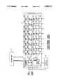
- FIGS. 7A-7B show a schematic circuit diagram of electrical control circuits of the preferred embodiment apparatus.
- FIG. 8 shows a schematic circuit diagram of relays and associated combinational logic by which valves of the control fluid circuits are operated in the preferred embodiment apparatus.
- FIG. 9 shows a schematic circuit diagram of input circuitry for receiving into the preferred embodiment apparatus data signals from an external controller such as a computer.
- FIGS. 10A-10B show a schematic circuit diagram of a circuit for controlling from the preferred embodiment apparatus an external electronic actuating fluid (e.g.,air) regulator.
- an external electronic actuating fluid e.g.,air
- FIG. 11 shows a schematic circuit diagram of a preferred alternate embodiment of a timer shown in FIG. 7B.
- the preferred embodiment of the present invention is contained within a housing 2 schematically shown in FIG. 2.
- a housing 2 schematically shown in FIG. 2.
- external devices which can be added to or used with the components contained within the housing 2.
- controller 4 such as a conventional microcomputer programmed to interact in a manner which will become apparent from the further description herein of the invention.
- a conventional electronic air regulator 6 is another example of an external device which can be used with the preferred embodiment of the present invention.
- the housing 2 of the preferred embodiment includes a front panel 8 shown in FIG. 1.
- Accessible on the front panel 8 are the following items which are implemented by conventional equipment: power on/off switch 10, which is switchable among an off position, a "dc" position wherein the internal circuits except for valve-actuating relays subsequently described are energized, and an "ac" position wherein all the internal circuits are energized; a local/remote switch 12, which is switchable between a "local” position wherein a pump contained within the housing 2 is automatically controlled by internal circuitry and a "remote” position wherein the pump is not automatically controlled by the internal circuitry but can be controlled by the external controller 4; a computer/manual switch 14, which is switchable between a "computer” position wherein the controller 4 can control a single pressurizing circuit within the housing 2 and multiplex to the pressurizing circuit pressure vessels connected to couplings of the housing 2 and a "manual” position wherein pressure setting and pressure vessel pressurizing are controlled through the components of the front panel
- the fluid systems generally depicted in FIG. 2 include a pressurizing fluid system and a control fluid system.
- the pressurizing fluid system can be pressurized to a suitable high pressure dependent upon specific equipment used, and the control fluid system is a lower pressure system providing air or other suitable fluid to operate high pressure valves within the pressurizing fluid system, for example.
- the pressurizing fluid system includes a tank valve 30 connected by a fluid conducting means 32 to a pump 34 and a plurality of channels 36 (eight channels 36a-36h are illustrated) through which the chambers of autoclaves or other pressure vessels (not shown) can be connected for being pressurized by the pump 34.
- a corresponding valve 38 In each of the channels 36 there is a corresponding valve 38.
- a pressure transducer 40 Located within the fluid conducting means 32 between the valves 30, 38 for monitoring the main system pressure is a pressure transducer 40, and located in each of the channels 36 between the respective valve 38 and a respective coupling for the external pressure vessel is a respective pressure transducer 42.
- the tank valve 30 is the main flow valve means for communicating a source of fluid for pressurizing the circuit with the fluid conducting means 32.
- the valves 38a-38h are the valves by which individually connected pressure vessels are communicated with the pressure within the fluid conducting means 32. Each valve 38 is dedicated for connecting to a respective pressure vessel.
- the valves 30, 38 can be conventional high pressure valves known in the art; however, in the preferred embodiment the preferred valve is the high pressure valve disclosed in U.S. Pat. Application Ser. No. 329,930, filed Mar. 29, 1989, now U.S. Pat. No. 4,917,349 and assigned to the assignee of the present invention.
- FIG. 3 Particular connections for the tank valve 30 in the preferred embodiment are shown in FIG. 3.
- the tank valve 30 receives an inlet flow from a suitable source of fluid to be used in pressurizing the system.
- a suitable fluid source is the municipal water supply.
- This is input through a coupling 44 on a back panel 45 of the housing 2.
- the inlet flow comes in from the coupling 44 through check valves 46 connected to the tank valve 30.
- a relief valve 48 is connected to the tank valve 30 to vent fluid to an external drain connectable at a coupling 50 on the back panel 45 and to a drain accumulator 52 inside the housing 2.
- the fluid conducting means 32 is conventional tubing suitable for conducting fluid, such as water, and for withstanding the pressure exerted through operation of the pump 34.
- the pump 34 is a small, but conventional pressurizing or intensifier pump which is mounted within the housing 2.
- the pump 34 includes a chamber 54 in which a piston 56 is movable between two limit positions which, for the orientation shown in FIG. 2, can be referred to as an upper limit position and a lower limit position which are the extremes to which the piston 56 can move within the pump 34.
- the chamber 54 is connected to the fluid conducting means 32 in a known manner.
- FIG. 4 The pressurizing fluid system or circuit of the preferred embodiment is more particularly illustrated in FIG. 4.
- Safety rupture disks 58a-58h are shown connected between respective valves 38a-38h and respective external couplings 60a-60h mounted on the back panel 45 of the housing 2 for receiving connections from the autoclaves or other devices to be pressurized.
- Channels 36a-36h branch from the main line of the fluid conducting means 32 at respective conventional T-connectors 62al-62h.
- the other elements of FIG. 4 correspond to the elements marked with the same reference numerals in FIG. 2.
- FIG. 2 Another fluid system of the preferred embodiment of the present invention shown in FIG. 2 is the low pressure, or control, fluid system.
- this includes fluid conducting means 64, such as conventional tubing suitable for conducting low pressure air, into which sole valves 66 and 68a-68h are connected.
- the low pressure or control fluid system also includes solenoid valves 70. This system is more particularly shown in FIGS. 5A-5B.
- an air supply inlet coupling 72 is mounted on the back panel 45 of the housing 2.
- An air conducting line 74 and an air conducting line 76 branch from a T-connector 78 connected to the coupling 72.
- the fluid conducting means 64 and a line 80 branch at a T-connector 82.
- the fluid conducting means 64 provides air to the solenoid valves 66, 68a-68h to which the respective high pressure valves 30, 38a-38h are connected.
- each of the solenoid valves 66, 68a-68h is controlled to provide air to either close or open the respective high pressure valve. This is apparent from the circuitry shown in FIG. 5A.
- a pump operating circuit which is generally identified in FIG. 2 by the valves 70.
- This includes a main control valve 84 into which air is input through a computer-controlled valve 86 and an air regulator 88 controlled by the knob 28 mounted on the front panel 8 shown in FIG. 1. Air from either the valve 86 or from the air regulator 88 is provided through the valve 84 to a valve 90 having an exhaust outlet 92 and a control port 94 connected to an "up" port 96 of the pump 34.
- a pump retract valve 100 Connected to a "down" port 98 of the pump 34 is a pump retract valve 100 having an inlet 102 connected through a lubricator 104 to the air supply inlet coupling 72 through a T-connector 106 having another branch connected to the inlet of the air regulator 88.
- the pump retract valve 100 has an exhaust outlet 108 and a control port 110.
- the pump control valves 84, 90, 100 are included within the pump control means for communicating a pump driving fluid, namely air in the preferred embodiment, to the pump 34.
- Pressurized air input through the valves 84, 90 acts to move the piston up for the orientation shown in FIG. 5, and pressurized air input through the valve 100 acts to move the piston down for the same orientation.
- the particular setting of the piston 56 within the pump 34 is established by the air pressure applied through these valves, particularly the adjustable air pressures applied through the valves 84, 90.
- One adjustable air pressure which can be switched through the valve 84 is manually selected by manually setting the air regulator 88 via the control knob 28.
- Another adjustable air pressure which can be switched through the valve 84 is provided via a means which is responsive to control from a computer.
- This means includes: the inlet valve 86 whose input 112 is adapted for receiving a pressure which is controlled by an external conventional electronic air regulator; means for operating the inlet valve 86 in response to control from the computer, which valve 86 operating means includes the combinational logic and relay circuit 114 shown in FIG. 8 and more particularly described hereinbelow; and means for controlling the electronic air regulator in response to control from the computer, which electronic air regulator control means includes the circuits shown in FIG. 10, which will be more particularly described hereinbelow.
- the pump control means further includes switch means for selecting which of the two pressurized air sources is passed by the pump control valves.
- this switch means includes the computer/manual switch 14 which controls the valve 84. When the switch 14 is in the "computer" position, the valve 84 connects the air pressure from the valve 86 to the inlet of the valve 90; and when the switch 14 is in the "manual” position, the manually controlled pressure from the air regulator 88 is communicated through the valve 84 to the inlet of the valve 90.
- valves 84, 90, 100 The means by which the valves 84, 90, 100 are controlled will be more particularly described hereinbelow with reference to the electrical system of the present invention.
- FIGS. 6-11 The electrical system of the preferred embodiment of the present invention will next be described with reference to FIGS. 6-11.
- the various valves which include the solenoid valves 66, 68 and the valves 86, 90, 100 by which the pump 34 is controlled (the valve 84 has already been described as being controlled by the switch 14).
- the electrical system is primarily mounted on a panel 116 (FIG. 6B) contained within the housing 2.
- the panel 116 contains conventional voltage regulators 118, 120.
- the panel 116 also contains circuits 122 more particularly shown in FIGS. 7-11.
- the circuits 122 are connected to the front panel switches 12, 14, 16, 18, 20 through a ribbon cable 124.
- the circuits 122 are connectable to the external controller 4, such as a microcomputer, through a ribbon cable 126.
- Other connectors of the circuits 122 are shown in FIG. 6B; the details of these connectors will become apparent from the subsequent description of the remaining drawings.
- the panel 116 also has connectors 128 and 130a-130h (connectors 130b-130g not shown to simplify the drawing).
- the connector 128 is used to provide the signal from the main pressure transducer 40 to the external controller 4 (if used), and the connectors 130a-130h are used to connect the individual channel pressure transducers 42a-42h to the external controller 4 (if used).
- the remainder of the wiring diagram shown in FIG. 6 is believed to be self-explanatory in that the remaining elements correspond to previously described elements as indicated by the use of like reference numerals, except for a linear potentiometer 132 which is used to detect the position of the piston 56 within the pump 34 in a known manner.
- the output of the linear potentiometer 132 is provided to the circuits 122 as shown in FIGS. 6A-6B.
- the signal from the linear potentiometer 132 is identified in FIG. 7A as the "position" signal.
- the manual front panel switches 20, 18, 16a-16h, 12, 14 are connected through the cable 124 to provide control signals T5, T6, T7-T14, T15, T16, respectively through a connector 133.
- control signals, D1-D14 can be provided to the circuits 122 from the external controller 4 through the cable 126 connected to a connector 135 identified in FIG. 9.
- These signals, T5-T16 and D1-D14 can be used to control a plurality of valve actuating means which include relays 134, 136, 138, 140, 142, 144, 146a-146h shown in FIG. 8.
- the relay 134 operates the valve 86; the relay 136 is not used in the preferred embodiment; the relay 138 operates the valve 90; the relay 140 is not used in the preferred embodiment; the relay 142 operates the retract valve 100; the relay 144 operates the solenoid valve 66 which in turn operates the tank valve 30; the relays 146a-146h operate the solenoid valves 68a-68h, respectively, which in turn operate the individual channel valves 38a-38h, respectively. Connections between these relays and valves are made through a connector 147. The uppermost connection to the connector 147 shown in FIG. 8 is the switched 110 VAC line which is energized only when the on/off switch 10 on the front panel 8 is in the "AC" position.
- the relay 144 and the solenoid valve 66 define a valve operating means for opening and closing the main flow valve 30, and each relay 146 and its respective solenoid valve 68 define valve operating means for opening and closing the respective valve 38.
- These operating means and the other relays shown in FIG. 8 are controlled through the circuits shown in FIGS. 7A, 7B and 8.
- the circuits shown in FIGS. 7A-7B are responsive to the "position" signal provided by the linear potentiometer 132 which is connected to the panel 116 through a connector 148 generally shown in FIG. 6 and more particularly shown in FIG. 9.
- the linear potentiometer 132 detects the position of the piston 56 in the pump 34 and generates a signal in correspondence with that position. That is, the linear potentiometer 132 converts the position into a corresponding electrical signal which is the "position" signal denoted in the drawings.
- the circuits shown in FIGS. 7A-7B include means 150, responsive to the pump piston position signal, for providing a limit position signal in response to the signal from the linear potentiometer 132 corresponding to the piston 56 having moved to one of its limit positions, namely its lowest position for the illustrated embodiment.
- This limit position signal of the preferred embodiment is labeled "Y2" in FIG. 7B.
- the means 150 includes signal holding means 152 for providing the limit position signal Y2 as a constant electrical signal, namely a digital signal of a fixed binary value.
- the holding means 152 of the preferred embodiment includes an integrated circuit digital latch 154 which generates and holds the signal Y2 as a logic "1" in response to a setting signal from a comparing means for comparing the linear potentiometer position signal with a first preset electrical signal which represents the piston 56 being at one of its limit positions.
- the comparing means is implemented by the circuit 156 shown in FIG. 7A.
- the preset signal of the comparing means is set by the circuit 158. This preset signal in the preferred embodiment sets the threshold below which the "position" signal is detected as indicating that the piston 56 is at its lowest limit of movement within the pump 34.
- the means 160 includes a signal holding means 162 which includes an integrated circuit digital latch 164.
- the comparing means includes the circuit 166, which includes the circuit 168 by which the preset signal is established to define the threshold above which the "position" signal is detected as indicating that the piston 56 is at its uppermost limit of movement within the pump 34.
- the control circuits shown in FIGS. 7A-7B further include control means 170 (FIG. 7B) for controlling the various valve operating means which include the relays 146a-146h and the corresponding solenoid valves 68a-68h.
- the means 170 responds to the signals Y1, Y2 by producing a control signal T20.
- the predetermined time includes the discharge time of a resistor capacitor network 171.
- the time is predetermined by a timing circuit 173 shown in FIG. 7, or more preferably by the alternative circuit 175 shown in FIG. 11, acting through the combinational logic of the OR gate 172.
- a control means 174 responds to the Y2, Y1 signals for controlling the valve operating means which includes the relay 144 and the solenoid valve 66. These open and close the tank valve 30.
- the C4' signal is provided in response to the combinational logic of an OR gate 176, to one input of which the timing circuit 178 is connected.
- the means 180 includes comparing means for comparing the "position" signal with a preset electrical signal representing the piston 56 being at a predetermined position between the two limit positions. This is implemented by a circuit 182, and the preset electrical signal is set by a circuit 184 shown in FIG. 7A.
- the set point of the illustrated circuit 184 represents the piston 56 being at substantially the midpoint of its stroke between its two end limit positions.
- the output of the comparing means is connected to the clear, or reset, inputs of the latches 154, 164 as shown in FIG. 7.
- the latches 154, 164 can be disabled by means of the T15 signal provided by the local/remote switch 12.
- the T15 signal is connected to the NAND logic gates 186, 188 shown in FIG. 7A.
- the circuits shown in FIGS. 7A-7B provide means not only for opening and closing the valves 30, 38a-38h, but also means for operating the valves 90, 100 to automatically move the piston 56 away from either of its limit positions when it has been detected that the piston 56 has reached a limit position. That is, the signals Y1, Y1', Y2 are applied to the combinational logic circuits shown in FIG. 8 connected to the relays 134, 136, 138, 140, 142. It is to be noted that these combinational logic circuits also provide means for connecting the relays 134-142 to the connector 135 terminals (FIG. 9) through which the D1-D5 data signals can be received from the external controller 4 so that the position of the piston 56 can also be controlled by the external controller 4.
- the T1-T4 signals shown in FIG. 8 are not implemented in the illustrated embodiment, but they can be if desired.
- the T5 signal is implemented, and is provided by the pump retract switch 20.
- combinational logic circuits shown in FIG. 8 include a NAND gate 190 which combines the T6 signal from the tank valve switch 18, the D6 data line from the respective connector 135 terminal, and the C4' control signal from the control circuits 174 shown in FIG. 7B.
- the remaining combinational logic circuits shown in FIG. 8 are for the individual channels 36a-36h, each of which circuits includes a respective NAND gate 192 for logically combining the signal from the respective switch 16, the respective data line from the connector 135 terminal, and the T20 signal from the control circuit 170 shown in FIG. 7.
- the aforementioned data lines are provided through buffers 194, 196 shown in FIG. 9.
- the inputs of the buffers are connected to the ribbon cable 126 at the connector 135.
- the buffers 194, 196 are enabled/disabled by means of the combinational logic circuit 200 whose inputs are the T15 (switch 12), T16 (switch 14), and T20 (control circuit 170) signals.
- switches 202 which are manually set to permit pump control pressure to be set either manually through the regulator 88 or electronically through the electronic air regulator 6 which can be connected to the air supply inlet 72 and channeled through the valve 86 (FIG. 5B). If the electronic air regulator 6 is used, it is controlled by an analog voltage provided at the output of a digital-to-analog converter (DAC) 204 shown in FIG. 10.
- the inputs of the DAC 204 are provided by counters 206a, 206b, 206c which are driven in response to a signal from a clock 208 in FIG. 10 and the "up" and “down” signals from FIG. 9 as coupled through the combinational logic circuit 210.
- a reset circuit 212 is also provided in the electronic air regulator control circuit shown in FIG. 10.
- the analog voltage provided at the output of the DAC 204 is provided through a connector 214.
- FIG. 9 Also shown in FIG. 9 is a connector 216 for making the indicated power connections.
- valve 84 shown in FIG. 5 When the computer/manual switch 14 is in the "computer" position, the valve 84 shown in FIG. 5 is controlled to pass air from the valve 86 to the valve 90. When the switch 14 is in the "manual" position, valve 84 communicates the air flow from the regulator 88 to the valve 90. Also when the switch 14 is in the "manual” position, the signal T16 from the switch 14 disables D 1 from affecting operation of the valve 86 through the combinational logic circuit 114 shown in FIG. 8.
- the buffers 194, 196 are disabled as just described so that control is entirely through the components of the front panel 8.
- autoclaves for example, to be pressurized have been connected to respective ones of the channels 36a-36h
- a municipal water supply for example
- pressurized air supply for example
- the tank valve 30 is opened using the switch 18 and the respective valves 38a-38g to which autoclaves have been connected are opened using the switches 16a-16h.
- Water, or other pressurizing fluid flows in through the open tank valve 30 until the system is adequately filled.
- the tank valve 30 and the opened valves 38a-38h are then closed by their respective front panel switches, and the pressure is brought up to the desired point by manipulating the control knob 28 of the air regulator 88.
- This pressure is displayed at least by the pressure gauge 22. This adjusts the air pressure applied to the piston 56 to thereby move the piston 56 to decrease or increase the effective volume of the pressurizing circuit to obtain the desired pressure. Once this pressure is attained, the channels which are to be brought up to this pressure are opened by actuating the respective switches 16a-16h.
- this mode of operation is most suited for controlling only one channel and connected device or several channels and connected devices which are to be maintained together at the same pressure; however, different pressures can be created in the pressurizing system and communicated to individual or groups of channels to bring connected devices up to selected pressures by sequentially manually operating the controls on the front panel 8.
- This type of manual multiplexing renders the automatic pressure control aspect of the circuitry shown in FIGS. 7 and 8 ineffective with respect to those channels which are not continuously in communication with the pressurizing circuit.
- any of these changes within the system can cause the piston 56 to move to either its lower limit position or its upper limit position ("lower” and “upper” for the orientation shown in FIG.2).
- the respective comparing means 156, 166 will detect this and set the respective latch 154, 164.
- the respective limit position signal Y1 or Y2 will switch to the high logic level and be communicated through a logic NOR gate 218 shown in FIG. 7B to the opposite logic level.
- the signal from the NOR gate 218 operates the control circuits 170, 174 to first switch the logic level of the T20 signal to the logic level by which each of the relays 146a-146h is controlled to operate the respective solenoid valve 68a-68h to close its respective valve 38a-38h, and then to switch the C4' signal to have a logic level which operates the relay 144 to control the solenoid valve 66 to open the tank valve 30.
- the piston 56 will be automatically moved back to its center point (or other location predetermined by the setting of the circuit 184 in FIG. 7A) by operation of the valves 90, 100 controlled by the Y1, Y1' and Y2 signals applied to the combinational logic circuits operating the relays 138, 142 (relays 136, 140 not used in the preferred embodiment) as shown in FIG. 8. It is to be recalled that the valve 86 operated by the relay 134, is not used in the local/manual mode and that the valve 84 is communicating the manually controlled air regulator 88 pressure to the valve 90.
- the foregoing automatic control also occurs in the local/computer mode.
- the circuitry shown in FIG. 8 is also responsive to the D1-14 signals received through the enabled buffers 194, 196 shown in FIG. 9.
- the air regulation must be by an external device because the valve 86 is now active and connected to the valve 84, which has been switched by the front panel switch 14 being moved to the "computer" position.
- Such an external air regulation device can be controlled by the circuitry shown in FIG. 10 as described hereinabove.
- the D7-D14 signals are disabled by the T20 signal when pressure is to be automatically corrected if the piston 56 moves to one of its extremes.
- the externally connected controller 4 such as a microcomputer, controls the system pressure, selects the channels to be pressurized, reads the position of the piston 56, and monitors the individual channel pressures via the pressure transducers 42a-42h.
- the external controller 4 compares each channel pressure with a prescribed set point entered into the controller for that channel. If the actual channel pressure is different from the prescribed set point: the pump 34 is actuated, via the pump control fluid circuit in FIG. 5B and its electrical control circuits in FIG.
- the present invention allows a small single-stroke intensifier pump to be used to automatically maintain pressures in autoclaves connected to the pump despite pressure changes which are due to, for example, expansions and loss of fluid through leaks.
- the present invention also permits multiplexing a number of autoclaves for pressurization by a single pressurizing pump. This reduces relative space requirements and costs.
- the present invention permits manual multiplexing and provides automatic control within itself, it is also adapted to receive computer or other external control which permits more efficient multiplexing and which permits a number of channels to be controlled to different pressure schedules if desired. Because pump piston position and pressure changes are detectable by an external controller, the compressability of the samples contained within the connected pressurized devices can be computed.
Landscapes
- Chemical & Material Sciences (AREA)
- Physics & Mathematics (AREA)
- General Physics & Mathematics (AREA)
- Organic Chemistry (AREA)
- Chemical Kinetics & Catalysis (AREA)
- Health & Medical Sciences (AREA)
- Engineering & Computer Science (AREA)
- Automation & Control Theory (AREA)
- Fluid Mechanics (AREA)
- Life Sciences & Earth Sciences (AREA)
- Analytical Chemistry (AREA)
- Biochemistry (AREA)
- General Health & Medical Sciences (AREA)
- Immunology (AREA)
- Pathology (AREA)
- Control Of Fluid Pressure (AREA)
- Apparatus For Disinfection Or Sterilisation (AREA)
Priority Applications (5)
| Application Number | Priority Date | Filing Date | Title |
|---|---|---|---|
| US07/359,809 US4990076A (en) | 1989-05-31 | 1989-05-31 | Pressure control apparatus and method |
| AU55849/90A AU618485B2 (en) | 1989-05-31 | 1990-05-24 | Pressure control apparatus and method |
| DE69018314T DE69018314D1 (de) | 1989-05-31 | 1990-05-25 | Druckregelvorrichtung. |
| EP90305733A EP0402018B1 (fr) | 1989-05-31 | 1990-05-25 | Dispositif de contrôle de pression |
| CA002017982A CA2017982C (fr) | 1989-05-31 | 1990-05-31 | Appareil et methode de regulation de la pression |
Applications Claiming Priority (1)
| Application Number | Priority Date | Filing Date | Title |
|---|---|---|---|
| US07/359,809 US4990076A (en) | 1989-05-31 | 1989-05-31 | Pressure control apparatus and method |
Publications (1)
| Publication Number | Publication Date |
|---|---|
| US4990076A true US4990076A (en) | 1991-02-05 |
Family
ID=23415373
Family Applications (1)
| Application Number | Title | Priority Date | Filing Date |
|---|---|---|---|
| US07/359,809 Expired - Lifetime US4990076A (en) | 1989-05-31 | 1989-05-31 | Pressure control apparatus and method |
Country Status (5)
| Country | Link |
|---|---|
| US (1) | US4990076A (fr) |
| EP (1) | EP0402018B1 (fr) |
| AU (1) | AU618485B2 (fr) |
| CA (1) | CA2017982C (fr) |
| DE (1) | DE69018314D1 (fr) |
Cited By (20)
| Publication number | Priority date | Publication date | Assignee | Title |
|---|---|---|---|---|
| US5556600A (en) * | 1993-11-23 | 1996-09-17 | Kerr-Mcgee Chemical Corporation | Method and apparatus for enhancing production of TiO2 |
| US5896882A (en) * | 1996-06-27 | 1999-04-27 | Northrop Grumman Corporation | Pressure control valve |
| DE10049078A1 (de) * | 2000-10-02 | 2002-04-18 | Aventis Res & Tech Gmbh & Co | Autoklaven-Array |
| US20030161763A1 (en) * | 2000-07-19 | 2003-08-28 | Symyx Technologies, Inc. | High pressure parallel reactor with individually isolatable vessels |
| US20030202911A1 (en) * | 2002-04-29 | 2003-10-30 | Symyx Technologies, Inc. | High pressure parallel reactor with individually sealable vessels |
| US6648609B2 (en) * | 2002-04-05 | 2003-11-18 | Berger Instruments, Inc. | Pump as a pressure source for supercritical fluid chromatography involving pressure regulators and a precision orifice |
| US6702025B2 (en) | 2002-02-11 | 2004-03-09 | Halliburton Energy Services, Inc. | Hydraulic control assembly for actuating a hydraulically controllable downhole device and method for use of same |
| US20050158865A1 (en) * | 1996-02-28 | 2005-07-21 | University Of Houston, Texas | System for testing catalysts at elevated pressures |
| US20070261852A1 (en) * | 2006-05-09 | 2007-11-15 | Surjaatmadja Jim B | Perforating and fracturing |
| US20080286170A1 (en) * | 2007-05-14 | 2008-11-20 | Symyx Technologies, Inc. | Parallel batch reactor |
| US20080286174A1 (en) * | 2007-05-14 | 2008-11-20 | Symyx Technologies, Inc. | Methods for chemical reactions in a parallel batch reactor |
| US20090057063A1 (en) * | 2007-08-30 | 2009-03-05 | Caterpillar Inc. | Lubrication system and method of control |
| US7807109B2 (en) | 2007-05-14 | 2010-10-05 | Freeslate, Inc. | Parallel batch reactor with pressure monitoring |
| US20110200976A1 (en) * | 2010-02-12 | 2011-08-18 | Mari Hou | Method and apparatus for in vitro testing for medical devices |
| US20110233299A1 (en) * | 2010-03-23 | 2011-09-29 | Berger Terry A | Low Noise Back Pressure Regulator for Supercritical Fluid Chromatography |
| US8215922B2 (en) | 2008-06-24 | 2012-07-10 | Aurora Sfc Systems, Inc. | Compressible fluid pumping system for dynamically compensating compressible fluids over large pressure ranges |
| US9163618B2 (en) | 2008-06-24 | 2015-10-20 | Agilent Technologies, Inc. | Automated conversion between SFC and HPLC |
| US9327325B1 (en) * | 2012-03-15 | 2016-05-03 | Aimm Technologies, Inc. | Portable resonance induction cleaning method |
| CN110215887A (zh) * | 2019-06-27 | 2019-09-10 | 重庆赛迪热工环保工程技术有限公司 | 一种超临界水气化系统间歇排放装置及控制方法 |
| CN116202870A (zh) * | 2023-02-17 | 2023-06-02 | 上海交通大学 | 薄壁管表面涂层开裂失效原位研究的试验装置 |
Families Citing this family (2)
| Publication number | Priority date | Publication date | Assignee | Title |
|---|---|---|---|---|
| EP2160237A2 (fr) * | 2007-05-14 | 2010-03-10 | Symyx Solutions Inc. | Réacteur à fonctionnement discontinu en parallèle |
| CN115552132B (zh) * | 2020-05-09 | 2026-05-15 | 爱默生过程管理阀门自动化公司 | 用于电动液压执行器的通用逻辑电路 |
Citations (30)
| Publication number | Priority date | Publication date | Assignee | Title |
|---|---|---|---|---|
| US1357196A (en) * | 1920-10-26 | of gotten- | ||
| US2984251A (en) * | 1957-12-23 | 1961-05-16 | Lear Inc | Pressure regulator |
| US2986898A (en) * | 1959-10-08 | 1961-06-06 | Vilter Mfg Co | Refrigeration system with refrigerant operated pump |
| CA635560A (en) * | 1962-01-30 | L. Morrison Willard | Means for controlling the pressure in an insulated tank containing liquefied methane | |
| GB958582A (en) * | 1960-08-23 | 1964-05-21 | Temptrip Ltd | Improvements in the means for operating the control valves of autoclaves |
| US3424370A (en) * | 1967-03-13 | 1969-01-28 | Carrier Corp | Gas compression systems |
| US3440256A (en) * | 1967-04-19 | 1969-04-22 | Du Pont | Sequential batch manufacture of tetramethyl lead |
| US3525596A (en) * | 1966-02-01 | 1970-08-25 | Chemetron Corp | Controlled discharge means for reaction apparatus |
| SU373707A1 (ru) * | 1971-02-26 | 1973-03-12 | Стабилизатор давления | |
| US3720487A (en) * | 1971-11-04 | 1973-03-13 | Phillips Petroleum Co | Pressure control |
| US3729000A (en) * | 1971-05-18 | 1973-04-24 | Puritan Bennett Corp | Compliance compensated ventilation system |
| US3847507A (en) * | 1972-05-17 | 1974-11-12 | Toyo Soda Mfg Co Ltd | Liquid supply system by pump |
| US3882861A (en) * | 1973-09-24 | 1975-05-13 | Vital Assists | Auxiliary control for a blood pump |
| US4093404A (en) * | 1975-12-19 | 1978-06-06 | Celanese Corporation | Apparatus for preparation of matrices containing frangible particulate matter |
| US4158639A (en) * | 1977-11-14 | 1979-06-19 | Autoclave Engineers, Inc. | Method of storing gases |
| JPS5510171A (en) * | 1978-07-10 | 1980-01-24 | Aisin Seiki Co Ltd | Hydraulic pressure controlling system for hydraulically operated apparatus |
| US4248268A (en) * | 1979-02-09 | 1981-02-03 | Choate J Robert | Fluid control system |
| US4285639A (en) * | 1979-06-12 | 1981-08-25 | Parker-Hannifin Corporation | Electronic control for variable displacement pumps |
| US4321014A (en) * | 1979-12-31 | 1982-03-23 | Polaroid Corporation | Constant flow pumping apparatus |
| DE3041045A1 (de) * | 1980-10-31 | 1982-05-13 | Maschinenbau Scholz Gmbh & Co Kg, 4420 Coesfeld | Verfahren und vorrichtung zur energierueckgewinnung bei haertungsprozessen von produkten in druckkesseln |
| US4397610A (en) * | 1981-03-09 | 1983-08-09 | Graco Inc. | Reciprocable pump with variable speed drive |
| US4430889A (en) * | 1981-12-02 | 1984-02-14 | Halliburton Company | Dynamic fluid testing apparatus and method |
| SU1160363A1 (ru) * | 1983-12-30 | 1985-06-07 | Pavel A Ozolin | Регулятор давления в автоклаве |
| US4559778A (en) * | 1978-05-30 | 1985-12-24 | Linde Aktiengesellschaft | Control device for a hydrostatic transmission |
| US4575313A (en) * | 1983-02-02 | 1986-03-11 | Halliburton Company | Digital pressure controller |
| US4622846A (en) * | 1985-11-05 | 1986-11-18 | Halliburton Company | Consistency and static gel strength measuring device and method |
| US4653313A (en) * | 1985-10-18 | 1987-03-31 | Halliburton Company | Positive stirring consistometer cup and method of using the same |
| US4666374A (en) * | 1983-01-11 | 1987-05-19 | Cooper Industries, Inc. | Methods and apparatus for producing uniform discharge and suction flow rates |
| JPS639792A (ja) * | 1986-06-27 | 1988-01-16 | Matsushita Electric Ind Co Ltd | 湯水混合装置 |
| US4917349A (en) * | 1989-03-29 | 1990-04-17 | Halliburton Company | Valve, and set point pressure controller utilizing the same |
Family Cites Families (5)
| Publication number | Priority date | Publication date | Assignee | Title |
|---|---|---|---|---|
| US2495670A (en) * | 1947-10-02 | 1950-01-24 | American Steel Foundries | Fluid apparatus |
| US3199341A (en) * | 1962-05-28 | 1965-08-10 | Continental Oil Co | Method and apparatus for measuring compressibility of porous material |
| US3412601A (en) * | 1966-08-31 | 1968-11-26 | Navy Usa | Multi-pressure cyclic fatigue system |
| FR2517923A1 (fr) * | 1981-12-04 | 1983-06-10 | Darragon Cie Ets E | Presse de stratification de circuits imprimes multicouches a systeme de commande hydropneumatique |
| DE3640236A1 (de) * | 1986-11-25 | 1988-06-01 | Rexroth Mannesmann Gmbh | Anordnung zum erzeugen hoher hydraulischer druecke |
-
1989
- 1989-05-31 US US07/359,809 patent/US4990076A/en not_active Expired - Lifetime
-
1990
- 1990-05-24 AU AU55849/90A patent/AU618485B2/en not_active Ceased
- 1990-05-25 EP EP90305733A patent/EP0402018B1/fr not_active Expired - Lifetime
- 1990-05-25 DE DE69018314T patent/DE69018314D1/de not_active Expired - Lifetime
- 1990-05-31 CA CA002017982A patent/CA2017982C/fr not_active Expired - Fee Related
Patent Citations (30)
| Publication number | Priority date | Publication date | Assignee | Title |
|---|---|---|---|---|
| CA635560A (en) * | 1962-01-30 | L. Morrison Willard | Means for controlling the pressure in an insulated tank containing liquefied methane | |
| US1357196A (en) * | 1920-10-26 | of gotten- | ||
| US2984251A (en) * | 1957-12-23 | 1961-05-16 | Lear Inc | Pressure regulator |
| US2986898A (en) * | 1959-10-08 | 1961-06-06 | Vilter Mfg Co | Refrigeration system with refrigerant operated pump |
| GB958582A (en) * | 1960-08-23 | 1964-05-21 | Temptrip Ltd | Improvements in the means for operating the control valves of autoclaves |
| US3525596A (en) * | 1966-02-01 | 1970-08-25 | Chemetron Corp | Controlled discharge means for reaction apparatus |
| US3424370A (en) * | 1967-03-13 | 1969-01-28 | Carrier Corp | Gas compression systems |
| US3440256A (en) * | 1967-04-19 | 1969-04-22 | Du Pont | Sequential batch manufacture of tetramethyl lead |
| SU373707A1 (ru) * | 1971-02-26 | 1973-03-12 | Стабилизатор давления | |
| US3729000A (en) * | 1971-05-18 | 1973-04-24 | Puritan Bennett Corp | Compliance compensated ventilation system |
| US3720487A (en) * | 1971-11-04 | 1973-03-13 | Phillips Petroleum Co | Pressure control |
| US3847507A (en) * | 1972-05-17 | 1974-11-12 | Toyo Soda Mfg Co Ltd | Liquid supply system by pump |
| US3882861A (en) * | 1973-09-24 | 1975-05-13 | Vital Assists | Auxiliary control for a blood pump |
| US4093404A (en) * | 1975-12-19 | 1978-06-06 | Celanese Corporation | Apparatus for preparation of matrices containing frangible particulate matter |
| US4158639A (en) * | 1977-11-14 | 1979-06-19 | Autoclave Engineers, Inc. | Method of storing gases |
| US4559778A (en) * | 1978-05-30 | 1985-12-24 | Linde Aktiengesellschaft | Control device for a hydrostatic transmission |
| JPS5510171A (en) * | 1978-07-10 | 1980-01-24 | Aisin Seiki Co Ltd | Hydraulic pressure controlling system for hydraulically operated apparatus |
| US4248268A (en) * | 1979-02-09 | 1981-02-03 | Choate J Robert | Fluid control system |
| US4285639A (en) * | 1979-06-12 | 1981-08-25 | Parker-Hannifin Corporation | Electronic control for variable displacement pumps |
| US4321014A (en) * | 1979-12-31 | 1982-03-23 | Polaroid Corporation | Constant flow pumping apparatus |
| DE3041045A1 (de) * | 1980-10-31 | 1982-05-13 | Maschinenbau Scholz Gmbh & Co Kg, 4420 Coesfeld | Verfahren und vorrichtung zur energierueckgewinnung bei haertungsprozessen von produkten in druckkesseln |
| US4397610A (en) * | 1981-03-09 | 1983-08-09 | Graco Inc. | Reciprocable pump with variable speed drive |
| US4430889A (en) * | 1981-12-02 | 1984-02-14 | Halliburton Company | Dynamic fluid testing apparatus and method |
| US4666374A (en) * | 1983-01-11 | 1987-05-19 | Cooper Industries, Inc. | Methods and apparatus for producing uniform discharge and suction flow rates |
| US4575313A (en) * | 1983-02-02 | 1986-03-11 | Halliburton Company | Digital pressure controller |
| SU1160363A1 (ru) * | 1983-12-30 | 1985-06-07 | Pavel A Ozolin | Регулятор давления в автоклаве |
| US4653313A (en) * | 1985-10-18 | 1987-03-31 | Halliburton Company | Positive stirring consistometer cup and method of using the same |
| US4622846A (en) * | 1985-11-05 | 1986-11-18 | Halliburton Company | Consistency and static gel strength measuring device and method |
| JPS639792A (ja) * | 1986-06-27 | 1988-01-16 | Matsushita Electric Ind Co Ltd | 湯水混合装置 |
| US4917349A (en) * | 1989-03-29 | 1990-04-17 | Halliburton Company | Valve, and set point pressure controller utilizing the same |
Non-Patent Citations (2)
| Title |
|---|
| PP. 2458 and 2459 of a Halliburton Services brochure dated at least one year prior to May 1989. * |
| Publication entitled Nowsco News Compact Pressurized Consistometer dated at least one year prior to May 1989, of Nowsco Well Service Limited. * |
Cited By (34)
| Publication number | Priority date | Publication date | Assignee | Title |
|---|---|---|---|---|
| US5556600A (en) * | 1993-11-23 | 1996-09-17 | Kerr-Mcgee Chemical Corporation | Method and apparatus for enhancing production of TiO2 |
| US20050158865A1 (en) * | 1996-02-28 | 2005-07-21 | University Of Houston, Texas | System for testing catalysts at elevated pressures |
| US5896882A (en) * | 1996-06-27 | 1999-04-27 | Northrop Grumman Corporation | Pressure control valve |
| US7141218B2 (en) | 2000-07-19 | 2006-11-28 | Symyx Technologies, Inc. | High pressure parallel reactor with individually isolatable vessels |
| US7172732B2 (en) | 2000-07-19 | 2007-02-06 | Symyx Technologies, Inc. | High pressure parallel reactor with individually isolatable vessels |
| US7754165B2 (en) | 2000-07-19 | 2010-07-13 | Symyx Solutions, Inc. | High pressure parallel reactor |
| US20070154361A1 (en) * | 2000-07-19 | 2007-07-05 | Symyx Technologies, Inc. | High pressure parallel reactor |
| US7556966B2 (en) | 2000-07-19 | 2009-07-07 | Symyx Technologies, Inc. | High pressure parallel reactor |
| US20030161763A1 (en) * | 2000-07-19 | 2003-08-28 | Symyx Technologies, Inc. | High pressure parallel reactor with individually isolatable vessels |
| US7018589B1 (en) | 2000-07-19 | 2006-03-28 | Symyx Technologies, Inc. | High pressure parallel reactor |
| US20060147354A1 (en) * | 2000-07-19 | 2006-07-06 | Symyx Technologies, Inc. | High pressure parallel reactor |
| US20040013565A1 (en) * | 2000-10-02 | 2004-01-22 | Bosch Boris E | Array of autoclaves |
| DE10049078A1 (de) * | 2000-10-02 | 2002-04-18 | Aventis Res & Tech Gmbh & Co | Autoklaven-Array |
| US6702025B2 (en) | 2002-02-11 | 2004-03-09 | Halliburton Energy Services, Inc. | Hydraulic control assembly for actuating a hydraulically controllable downhole device and method for use of same |
| US6648609B2 (en) * | 2002-04-05 | 2003-11-18 | Berger Instruments, Inc. | Pump as a pressure source for supercritical fluid chromatography involving pressure regulators and a precision orifice |
| US7122159B2 (en) | 2002-04-29 | 2006-10-17 | Symyx Technologies, Inc. | High pressure parallel reactor with individually sealable vessels |
| US20030202911A1 (en) * | 2002-04-29 | 2003-10-30 | Symyx Technologies, Inc. | High pressure parallel reactor with individually sealable vessels |
| US7337844B2 (en) | 2006-05-09 | 2008-03-04 | Halliburton Energy Services, Inc. | Perforating and fracturing |
| US20070261852A1 (en) * | 2006-05-09 | 2007-11-15 | Surjaatmadja Jim B | Perforating and fracturing |
| US20080286174A1 (en) * | 2007-05-14 | 2008-11-20 | Symyx Technologies, Inc. | Methods for chemical reactions in a parallel batch reactor |
| US20080286170A1 (en) * | 2007-05-14 | 2008-11-20 | Symyx Technologies, Inc. | Parallel batch reactor |
| US7655191B2 (en) | 2007-05-14 | 2010-02-02 | Symyx Solutions, Inc. | Methods for chemical reactions in a parallel batch reactor |
| US7807109B2 (en) | 2007-05-14 | 2010-10-05 | Freeslate, Inc. | Parallel batch reactor with pressure monitoring |
| US20090057063A1 (en) * | 2007-08-30 | 2009-03-05 | Caterpillar Inc. | Lubrication system and method of control |
| US8387755B2 (en) * | 2007-08-30 | 2013-03-05 | Caterpillar Inc. | Lubrication system and method of control |
| US8215922B2 (en) | 2008-06-24 | 2012-07-10 | Aurora Sfc Systems, Inc. | Compressible fluid pumping system for dynamically compensating compressible fluids over large pressure ranges |
| US9163618B2 (en) | 2008-06-24 | 2015-10-20 | Agilent Technologies, Inc. | Automated conversion between SFC and HPLC |
| US20110200976A1 (en) * | 2010-02-12 | 2011-08-18 | Mari Hou | Method and apparatus for in vitro testing for medical devices |
| US20110233299A1 (en) * | 2010-03-23 | 2011-09-29 | Berger Terry A | Low Noise Back Pressure Regulator for Supercritical Fluid Chromatography |
| US8419936B2 (en) | 2010-03-23 | 2013-04-16 | Agilent Technologies, Inc. | Low noise back pressure regulator for supercritical fluid chromatography |
| US9345989B2 (en) | 2010-03-23 | 2016-05-24 | Agilent Technologies, Inc. | Low noise back pressure regulator for supercritical fluid chromatography |
| US9327325B1 (en) * | 2012-03-15 | 2016-05-03 | Aimm Technologies, Inc. | Portable resonance induction cleaning method |
| CN110215887A (zh) * | 2019-06-27 | 2019-09-10 | 重庆赛迪热工环保工程技术有限公司 | 一种超临界水气化系统间歇排放装置及控制方法 |
| CN116202870A (zh) * | 2023-02-17 | 2023-06-02 | 上海交通大学 | 薄壁管表面涂层开裂失效原位研究的试验装置 |
Also Published As
| Publication number | Publication date |
|---|---|
| AU618485B2 (en) | 1991-12-19 |
| CA2017982C (fr) | 1994-03-15 |
| CA2017982A1 (fr) | 1990-11-30 |
| EP0402018A1 (fr) | 1990-12-12 |
| DE69018314D1 (de) | 1995-05-11 |
| AU5584990A (en) | 1990-12-06 |
| EP0402018B1 (fr) | 1995-04-05 |
Similar Documents
| Publication | Publication Date | Title |
|---|---|---|
| EP0402018B1 (fr) | Dispositif de contrôle de pression | |
| US9404603B2 (en) | Valve manifold | |
| US5622482A (en) | Pump using shape memory alloys | |
| US4215567A (en) | Method and apparatus for testing a production stream | |
| US6435010B1 (en) | Leak detection system | |
| US5257528A (en) | Device for studying the aging of a circulating fluid under specific imposed conditions | |
| US20040069619A1 (en) | Automatable measuring, cleaning and calibration device for pH-electrodes or electrodes for measuring redox potentials | |
| EP0280811B1 (fr) | Procédé et dispositif de mesure de la pression d'une vapeur | |
| CN106525358B (zh) | 阀门压力测试系统及方法 | |
| US4953618A (en) | Injection manifold and method | |
| US3906726A (en) | Positioner methods and apparatus | |
| US5027902A (en) | Self-cycling pump apparatus and method | |
| EP0096887A2 (fr) | Dispositif pour tester la résistance à la pression interne de tuyaux en plastique | |
| EP0321376B1 (fr) | Appareil pour contrôler la mise en marche et l'arrêt d'une pompe hydraulique | |
| US5333636A (en) | Controlled high pressure relief for small volumes | |
| US4273742A (en) | Drain apparatus for the reaction vessel in an atomic absorption instrument | |
| US6081767A (en) | Method and device for determining the amount of undissolved gas in a hydraulic system | |
| EP0118967A1 (fr) | Dispositif de commande de la pression dans une chambre | |
| EP1904715B1 (fr) | Procede et systeme connexe de reglage de la pression de commande de fond de trou | |
| JP3311829B2 (ja) | オートサンプラ | |
| SU1497384A1 (ru) | Стенд дл испытани гидроагрегатов | |
| SU1183666A1 (ru) | Устройство дл управлени процессом пакеровки с гидромеханическим пакером | |
| SU1056139A1 (ru) | Стенд дл ресурсных испытаний регул торов давлени с узлом разгрузки компрессора | |
| JPH02280206A (ja) | 圧力設定器 | |
| SU759706A1 (ru) | Способ подготовки установки высокого давления к повторному циклу исследовании 1 |
Legal Events
| Date | Code | Title | Description |
|---|---|---|---|
| AS | Assignment |
Owner name: HALLIBURTON COMPANY, OK A CORP. OF DE, OKLAHOMA Free format text: ASSIGNMENT OF ASSIGNORS INTEREST.;ASSIGNORS:LYNCH, MICHAEL J.;TURNER, G. ALLEN;EHLERT, MARK;AND OTHERS;REEL/FRAME:005127/0791;SIGNING DATES FROM 19890628 TO 19890720 |
|
| STCF | Information on status: patent grant |
Free format text: PATENTED CASE |
|
| FPAY | Fee payment |
Year of fee payment: 4 |
|
| FPAY | Fee payment |
Year of fee payment: 8 |
|
| FPAY | Fee payment |
Year of fee payment: 12 |