US5004994A - Push-to-trip high-amp circuit breaker - Google Patents
Push-to-trip high-amp circuit breaker Download PDFInfo
- Publication number
- US5004994A US5004994A US07/528,312 US52831290A US5004994A US 5004994 A US5004994 A US 5004994A US 52831290 A US52831290 A US 52831290A US 5004994 A US5004994 A US 5004994A
- Authority
- US
- United States
- Prior art keywords
- contact
- circuit breaker
- bar
- bistable element
- housing
- Prior art date
- Legal status (The legal status is an assumption and is not a legal conclusion. Google has not performed a legal analysis and makes no representation as to the accuracy of the status listed.)
- Expired - Lifetime
Links
- 238000010292 electrical insulation Methods 0.000 claims description 4
- 230000007246 mechanism Effects 0.000 claims description 4
- 230000009471 action Effects 0.000 description 3
- 238000004519 manufacturing process Methods 0.000 description 3
- 230000036316 preload Effects 0.000 description 2
- 230000000007 visual effect Effects 0.000 description 2
- BQCADISMDOOEFD-UHFFFAOYSA-N Silver Chemical compound [Ag] BQCADISMDOOEFD-UHFFFAOYSA-N 0.000 description 1
- 239000000956 alloy Substances 0.000 description 1
- 229910045601 alloy Inorganic materials 0.000 description 1
- 230000000712 assembly Effects 0.000 description 1
- 238000000429 assembly Methods 0.000 description 1
- 230000000295 complement effect Effects 0.000 description 1
- 239000002131 composite material Substances 0.000 description 1
- 238000010276 construction Methods 0.000 description 1
- 230000000994 depressogenic effect Effects 0.000 description 1
- 230000005611 electricity Effects 0.000 description 1
- 239000000463 material Substances 0.000 description 1
- 230000013011 mating Effects 0.000 description 1
- 238000000034 method Methods 0.000 description 1
- 238000012986 modification Methods 0.000 description 1
- 230000004048 modification Effects 0.000 description 1
- 230000008569 process Effects 0.000 description 1
- 238000005070 sampling Methods 0.000 description 1
- 238000007789 sealing Methods 0.000 description 1
- 229910052709 silver Inorganic materials 0.000 description 1
- 239000004332 silver Substances 0.000 description 1
Images



Classifications
-
- H—ELECTRICITY
- H01—ELECTRIC ELEMENTS
- H01H—ELECTRIC SWITCHES; RELAYS; SELECTORS; EMERGENCY PROTECTIVE DEVICES
- H01H73/00—Protective overload circuit-breaking switches in which excess current opens the contacts by automatic release of mechanical energy stored by previous operation of a hand reset mechanism
- H01H73/22—Protective overload circuit-breaking switches in which excess current opens the contacts by automatic release of mechanical energy stored by previous operation of a hand reset mechanism having electrothermal release and no other automatic release
- H01H73/28—Protective overload circuit-breaking switches in which excess current opens the contacts by automatic release of mechanical energy stored by previous operation of a hand reset mechanism having electrothermal release and no other automatic release reset by rotatable knob or wheel
-
- H—ELECTRICITY
- H01—ELECTRIC ELEMENTS
- H01H—ELECTRIC SWITCHES; RELAYS; SELECTORS; EMERGENCY PROTECTIVE DEVICES
- H01H73/00—Protective overload circuit-breaking switches in which excess current opens the contacts by automatic release of mechanical energy stored by previous operation of a hand reset mechanism
- H01H73/22—Protective overload circuit-breaking switches in which excess current opens the contacts by automatic release of mechanical energy stored by previous operation of a hand reset mechanism having electrothermal release and no other automatic release
- H01H73/30—Protective overload circuit-breaking switches in which excess current opens the contacts by automatic release of mechanical energy stored by previous operation of a hand reset mechanism having electrothermal release and no other automatic release reset by push-button, pull-knob or slide
- H01H73/303—Protective overload circuit-breaking switches in which excess current opens the contacts by automatic release of mechanical energy stored by previous operation of a hand reset mechanism having electrothermal release and no other automatic release reset by push-button, pull-knob or slide with an insulating body insertable between the contacts when released by a bimetal element
Definitions
- the present invention relates to a high-amp circuit breaker assembly in general and more particularly a breaker having a manual reset mechanism which utilizes a substantially rectangular, bimetallic, bistable, thermally active element to provide for overload protection, and manual trip means to place the breaker in an open circuit condition.
- Circuit breakers when mounted through a panel on a surface usually have their terminals on different sides of the circuit breaker assembly.
- the manual reset circuit breakers are generally constructed so that it is not readily seen that the circuit breaker has opened to protect the circuit from an overload or a surge in current.
- the bimetallic bistable elements used to open and close the breaker circuit usually require a relatively complex structure to operate with the quickness that is necessary to protect a circuit from damage.
- the structure used is a cylindrical bimetallic disc that has a small clearance hole at the center. The disc is then stamped into a dome shaped element via a radial forming die. A finely threaded screw is placed through the center hole and engaged into a mating female thread within the units main housing. The screw is tightened to preload the central dome or hump.
- the disc has a pair of contacts on opposite sides of the diameter. In the assembly the disc contacts have corresponding contacts attached to termination lugs.
- the disc circuit breaker When the disc circuit breaker encounters an over-current, the disc goes from concave to convex to open the circuit and returns in the automatic reset style when the over-current is not present and a predetermined time has past to allow the element to sufficiently cool.
- the manual reset style operates similarly except that the bistable element is over-stressed so that when an over-current causes the convex condition, the element must be returned to the concave form by physical force via a push-button resetting mechanism.
- circuit breakers for low voltage DC applications with high amperage rating utilize generally large and broad forming radii that as a process exhibits high variability. This results in circuit breakers which are relatively costly to manufacture because the manufacturing process is labor intensive.
- Each unit has to be individually calibrated at the factory. The center adjusting screw for each unit must be manually tightened to bring the contacts into a pre-load condition. Then each unit must be tested to be sure it is properly calibrated to open and close as required to protect a circuit.
- circuit breakers provide a means to work on electrical equipment without disconnecting a battery terminal or otherwise removing the electrical source from the circuit; however, they are relatively expensive, complex, and not available or suitable in this class of low voltage, high current D.C. design.
- a bistable thermally active element is rectangular with a width greater than 1/2 of its length. One end of the element is fixed and the other end has a contact attached thereto. The other end with contact attached is the moveable end and snaps from a first normal position to a second position. The snap action of this bistable element and its inherent electrical resistance determine the opening point particular over-load amperage.
- the element has at least one dimple formed thereon to provide the desired snap action.
- a low voltage high amp circuit breaker in another embodiment of the invention, includes a housing and one pair of terminals fixed to the housing and extending from the same outer side of the housing. In yet another embodiment of the invention, a low voltage high amp circuit breaker includes a housing and one pair of terminals fixed to the housing and extending from the opposite side of the housing. Within a cavity formed in the housing are first, second and third contacts electrically connected respectively to said bistable element and said pair of terminals. The first fixed contact is fixedly attached to one end of a rectangular thermally responsive bimetallic bistable element.
- Attached to the other end of the bistable element is a contact.
- the second contact is positioned relative to the fixed third contact so that they are normally in electrical contact.
- the element is so calibrated that when an overload is encountered the element's active end snaps to a second position which separates the second contact from a third fixed contact attached to a terminal in close proximity to the second contact to open the circuit of the circuit breaker. After a predetermined time, the element is calibrated to snap back into its first position.
- the element has at least one dimple formed thereon.
- a manual-reset high-amp circuit breaker having a generally central closed cavity.
- the rectangular, bistable, thermally responsive element, as described above is mounted in said cavity.
- the one end of the bistable element is fixed to a contact for a first terminal and is generally not moveable.
- the other end of the bistable element has a second contact thereon that is normally in electrical contact with a third contact that is for the second terminals.
- a rotatable shaft is mounted in the cavity and extend outside of the housing.
- a manual reset lever is attached to the rotatable shaft and pivots when the shaft rotates.
- An extension blade is attached to the shaft and positioned adjacent the element contact.
- a spring means is attached to said shaft.
- the extension blade and spring are positioned so as not to interfere with the normal "on" position of the circuit breaker, i.e., electrical contact occurs between the second and third contacts to assure a current flow through the device.
- the spring turns the shaft to position the extension blade between the second and third contacts.
- the reset lever is rotated and visually shows that the circuit breaker is in its open condition.
- the overload condition is terminated and a predetermined time has passed, the second contact is prevented from contacting the third contact by the extension blade.
- the circuit breaker remains open, or tripped, and nonconducting until it is manually reset.
- the reset lever is attached to the shaft so that when the reset lever is manually pivoted to its reset position, the extension blade is moved from between the second and third contacts to a ready non-insulating position and the second and third contacts return to their "on" or electrical contact position.
- the reset lever and both terminals are all on the same external side of the housing to provide for easy visual means to determine the condition of the circuit breaker and to provide an easy electrical access to the circuit breaker.
- a manual trip button is provided which manually separates the second and third contacts to the open circuit position.
- the extension blade attached to the rotatable shaft then rotates between the second and third contact as described above and holds the breaker in the open circuit position until it is manually reset.
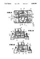
- FIG. 1 is a top, front, right perspective view of a surface mounting type circuit breaker of the present invention having a manual reset and push-to-trip mechanism;
- FIG. 2 is a top plan view of FIG. 1;
- FIG. 3 is a cutaway view along lines 3--3 of a circuit breaker according to the present invention incorporating a push-to-trip button;
- FIG. 4 is a partial top sectional view taken along lines 4--4 of FIG. 3;
- FIG. 5 is a partial section view taken along lines 5--5 of FIG. 4;
- FIG. 6 is a partial sectional view taken along lines 6--6 of FIG. 4.
- FIG. 7 is an enlarged partial sectional view of FIG. 4;
- FIG. 8 is a top perspective view of the bimetallic bistable element of the present invention.
- FIG. 9 is a sectional view taken along lines 9--9 of FIG. 9.
- FIG. 10 is a perspective view, disassembled, of a circuit breaker according to the present invention.
- the circuit breaker has two external terminals 21, 22 extending from the same external side of the breaker.
- the terminals are preferably mounted on opposite sides of a central housing 23. Thus, the terminals may be reached easily from one side of the circuit breaker.
- a blank preferably hollow raised housing 27 and a pivoting reset lever 28 On top of the central housing cover 24 is a blank preferably hollow raised housing 27 and a pivoting reset lever 28.
- the reset lever has a handle 29 which pivots about its end 31 as is described in more detail below.
- Blank housing 27 is utilized to give an aesthetic appearance to the circuit breaker and is shaped to complement the features of the reset lever.
- a stationary portion 32 prevents the reset lever handle 29 from being accidentally turned in the direction of the stationary portion 32. If there was no stop means 32, the accidental turning of the reset handle 29 during shipping or use would most likely damage the circuit breaker and require replacement.
- the manual reset lever is in a side by side fit with the blank housing and is rotated or pivoted in the direction Z shown when there is an overload current of a predetermined magnitude.
- the reset lever When the reset lever is pivoted to its trip position (shown in phantom in FIG. 2), the circuit of the circuit breaker is opened to prevent electricity from passing therethrough. After the overload condition ceases and a predetermined time has passed the reset lever handle 29 can be returned manually to the position shown in FIGS. 1 and 2 and return the circuit breaker to its closed circuit position.
- Push-to-trip button 80 may be used to manuallY place the breaker in an open circuit condition as described in more detail below.
- a bimetallic, bistable, thermally activated element 41 shown in FIGS. 3 , 5, and 8 are mounted in the cavity 33.
- the bistable mechanical element is manufactured to have a predetermined over current snap action.
- the bistable element 41 in a non-overload condition is in a first relatively horizontal position as shown in FIG. 5. When there is an overload, the bistable element heats up and deflects to snap into a second position (not shown.)
- the bimetallic bistable element 41 is best shown in FIGS. 8-10.
- the bistable element is a known thermally reactive composite alloy.
- the bistable element has a top surface 42, bottom surface 43, a fixed end 44, a moveable end 46 and two sides 47, 48.
- a weld disc 49 and a preferably high silver content contact 51 are welded to the moveable end 46 of the element.
- the weld disc is attached to the top surface 42 and the contact 51 to the bottom surface 43. Both the contact 51 and the weld disc 49 extend inwardly from the top edge of the end 46 and are preferably in the center of the end 46.
- Hole 52 is located on end 44. Adjacent each side 47 and 48 is a dimple 53. The dimples are concave on the top surface 42, convex on the bottom surface 43. The length of the element is 1 5/16 to 11/2 inches and the width is 1 to 1 1/4 inches. Thus, the width is greater than 1/2 the length.
- bistable elements of the present invention can be accurately calibrated in mass.
- Bistable elements for a particular overload will generally all have the same size having the same number and size of dimples and made from the same material.
- only a representative sampling of the bistable elements and their respective high-amp circuit breakers are necessary.
- the advantages of mass producing the circuit breakers without the necessity of having individual calibration is one of the advantageous economical features of the present invention.
- the high-amp low voltage circuit breakers which were generally used prior to this invention, use a disc construction which requires almost individual calibration.
- the manual reset circuit breaker has an insulating plastic central housing 23 and a insulating plastic cover 24.
- the cover is sealed to the housing.
- rivets 26 are used to fix the cover to the housing, any appropriate fastening means can be used.
- an appropriate seal 54 which extends over the entire body cavity.
- a rotatable non-conductive insulating shaft 56 Within the body cavity 33 and adjacent end wall 39, there is located a rotatable non-conductive insulating shaft 56.
- the shaft 56 has two ends 57, 58.
- the one end 58 is inserted in a blind hole 59 formed in the base of the cavity and its other end 57 extending outside of the cavity and through the cover 23 for a predetermined distance.
- Another seal 61 aids in the sealing of the shaft 56 from the exterior of the housing cover.
- the manual reset lever 28 is pressure fitted onto the rod end 57 to provide the arrangement shown in FIG. 1, 2, and 3. Therefore, when the circuit breaker is open, the reset lever is rotated or pivoted in the direction Z for a predetermined distance.
- the rotated reset handle is a visual indication that the breaker must be reset. The resetting must be done manually.
- the shaft or rod 56 has a first spring attaching bar 62 integrally extending therefrom. This bar 62 is used to connect one end of an extension spring 63. Spaced a predetermined distance below the first bar is a non-conductive heat resistant second extension bar or extension blade 64. The second extension blade 64 extends a predetermined distance substantially radially from the shaft 56.
- the extension blade is spaced a predetermined distance above the base of the housing.
- the extension blade has a rudder-like or similar form with a first straight edge, a predetermined width and a rounded portion.
- the size and length of the second extension blade 64 is determined so that it ca fit between the element contact 51 and a terminal contact 66 to maintain an electrical insulation therebetween and to keep the two contacts separated if desired. This will be described in greater detail hereinafter.
- the bistable element 41 is mechanically staked at its one end 44 to the first terminal contact 67.
- the bistable element is sized and the rotatable shaft 56 is mounted in the cavity such that the other end 46 is adjacent to the rotatable shaft.
- the mounting height of the bistable element in the cavity is such that the contact 51 is generally in the same plane as the second extension blade 64.
- the flat side surface of the second extension blade 64 rests against the end surface of the circular element contact 51 when the breaker circuit is in its closed position.
- the second extension blade 64 is urged towards the contact 51 by the extension spring 63 which has its other end connected to the cover attachment and spring holder 68.
- This cover attachment and spring holder 68 is located on one side of the inside of the housing.
- the second terminal has located within the housing the stationary contact 66 which is situated just below the element contact 51, adjacent to the rotatable shaft 56 and below the second extension blade 64.
- the extension blade is such that it extends at least to the center of the element contact 51 and the terminal contact 66 when the circuit breaker is in its open position.
- Push-to-trip button 80 is slidably mounted in raised portion 27 of cover plate 24. The lower portion of button 80 rests against lift arm 82.
- Lift arm 82 is comprised of fingers 84, bar 86, and plate 88. Bar 86 rests in slots in housing 23.
- Lift bracket 92 is attached to weld disk 49 of bimetallic biseal element 41. Lift bracket 92 has arms 94 which normally rests on fingers 84 of lift arm 82.
- the high-amp circuit breaker In operation, the high-amp circuit breaker is in its normal closed position as shown in FIG. 7.
- the spring 63 is in its extended position urging the extension blade 64 towards and against the element contact 51.
- the terminal contact 66 and the element contact 51 are in electrical contact with each other.
- the bistable element 41 snaps its end 46 to the second position wherein the element contact is raised a predetermined distance above the terminal contact and the blade 64 is then moved between the two contacts shown in FIG. 3.
- the blade 64 in this position electrically insulates the two contacts from each other and prevents contact 51 from contacting terminal contact 66 until the breaker is reset. Referring to FIG.
- the reset lever when there is an overload, the reset lever is moved in a direction such that the handle is moved away from the blank housing as shown in phantom.
- the resetting is a quick and easy operation.
- the lever is merely turned towards the blank housing and the shaft is rotated such that the extension blade 64 is moved from between the element contact 51 and the second terminal contact 66.
- the spring 63 is extended.
- the extension blade 64 is removed from between the two contacts 51 and 56, the element contact 51 returns to the position shown in FIG. 5 and the extension blade 64 contacts the side of the element contact 51 as shown.
- push-to-trip button 80 is depressed which forces plate 88 downward rotating lift arm 82 about bar 86. This raises fingers 84 of lift arm 82 which also raises arms 94 of lift bracket 92 pulling one end of thermal bistable element in an upward direction. This allows blade 64 to move between contact 51 and 66.
Landscapes
- Thermally Actuated Switches (AREA)
- Breakers (AREA)
Priority Applications (2)
| Application Number | Priority Date | Filing Date | Title |
|---|---|---|---|
| US07/528,312 US5004994A (en) | 1990-05-24 | 1990-05-24 | Push-to-trip high-amp circuit breaker |
| CA002030167A CA2030167C (fr) | 1990-05-24 | 1990-11-16 | Disjoncteur haute intensite de type "appuyer pour declencher" |
Applications Claiming Priority (1)
| Application Number | Priority Date | Filing Date | Title |
|---|---|---|---|
| US07/528,312 US5004994A (en) | 1990-05-24 | 1990-05-24 | Push-to-trip high-amp circuit breaker |
Publications (1)
| Publication Number | Publication Date |
|---|---|
| US5004994A true US5004994A (en) | 1991-04-02 |
Family
ID=24105153
Family Applications (1)
| Application Number | Title | Priority Date | Filing Date |
|---|---|---|---|
| US07/528,312 Expired - Lifetime US5004994A (en) | 1990-05-24 | 1990-05-24 | Push-to-trip high-amp circuit breaker |
Country Status (2)
| Country | Link |
|---|---|
| US (1) | US5004994A (fr) |
| CA (1) | CA2030167C (fr) |
Cited By (17)
| Publication number | Priority date | Publication date | Assignee | Title |
|---|---|---|---|---|
| US5089799A (en) * | 1991-01-25 | 1992-02-18 | Sorenson Richard W | Thermal switch/breaker |
| USD357669S (en) | 1993-02-24 | 1995-04-25 | Cooper Industries, Inc. | Shielded reset lever for a firewall-mount high amp circuit breaker |
| US5539371A (en) * | 1995-09-08 | 1996-07-23 | Yu; Tsung-Mou | Fuseless breaking switch |
| USD467556S1 (en) | 2001-04-25 | 2002-12-24 | Blue Sea Systems | Circuit breaker face |
| USD467883S1 (en) | 2001-04-25 | 2002-12-31 | Blue Sea Systems | Circuit breaker face |
| US6538549B1 (en) | 2001-08-30 | 2003-03-25 | Blue Sea Systems | Advanced electrical circuit breaker system and method |
| US6707368B2 (en) | 2001-07-18 | 2004-03-16 | Cooper Technologies Company | Manually trippable circuit breaker |
| US6714116B1 (en) | 2002-01-22 | 2004-03-30 | Rototech Electrical Components, Inc. | Circuit breaker switch |
| US6744345B2 (en) | 2002-05-06 | 2004-06-01 | Cooper Technologies | Mid-range circuit breaker |
| USD513496S1 (en) * | 2004-05-31 | 2006-01-10 | Comet Corporation | Distribution switch |
| US20060164192A1 (en) * | 2005-01-27 | 2006-07-27 | Jacek Korczynski | Overcurrent device feed through junction block |
| US20070115089A1 (en) * | 2005-11-21 | 2007-05-24 | Anand Krishnamurthy | Thermal circuit breaker |
| US8378245B2 (en) | 2010-08-09 | 2013-02-19 | Eaton Corporation | Electrical switching apparatus, and handle assembly and push-to-trip mechanism therefor |
| US20130322050A1 (en) * | 2012-05-31 | 2013-12-05 | Daniel Douglas David | Modular circuit breaker, kit, and methods of manufacture and assembly |
| US10109443B2 (en) | 2017-03-16 | 2018-10-23 | Cooper Technologies Company | High amp circuit breaker with terminal isolation fastener cap |
| US20230102517A1 (en) * | 2021-09-24 | 2023-03-30 | MP Hollywood | Circuit breaker with integral fuse mounting stud |
| US20230386775A1 (en) * | 2022-05-26 | 2023-11-30 | Hubbell Incorporated | Compact recloser |
Citations (3)
| Publication number | Priority date | Publication date | Assignee | Title |
|---|---|---|---|---|
| US2720416A (en) * | 1951-10-16 | 1955-10-11 | Underwood Electric & Mfg Co In | Snap acting thermostatic elements and methods of making the same |
| US3723929A (en) * | 1972-04-07 | 1973-03-27 | Furnas Electric Co | Bimetallic circuit overload protector |
| US4814739A (en) * | 1987-12-18 | 1989-03-21 | Eaton Corporation | Combination push/pull electric switch and circuit breaker |
-
1990
- 1990-05-24 US US07/528,312 patent/US5004994A/en not_active Expired - Lifetime
- 1990-11-16 CA CA002030167A patent/CA2030167C/fr not_active Expired - Lifetime
Patent Citations (3)
| Publication number | Priority date | Publication date | Assignee | Title |
|---|---|---|---|---|
| US2720416A (en) * | 1951-10-16 | 1955-10-11 | Underwood Electric & Mfg Co In | Snap acting thermostatic elements and methods of making the same |
| US3723929A (en) * | 1972-04-07 | 1973-03-27 | Furnas Electric Co | Bimetallic circuit overload protector |
| US4814739A (en) * | 1987-12-18 | 1989-03-21 | Eaton Corporation | Combination push/pull electric switch and circuit breaker |
Cited By (25)
| Publication number | Priority date | Publication date | Assignee | Title |
|---|---|---|---|---|
| US5089799A (en) * | 1991-01-25 | 1992-02-18 | Sorenson Richard W | Thermal switch/breaker |
| USD357669S (en) | 1993-02-24 | 1995-04-25 | Cooper Industries, Inc. | Shielded reset lever for a firewall-mount high amp circuit breaker |
| US5539371A (en) * | 1995-09-08 | 1996-07-23 | Yu; Tsung-Mou | Fuseless breaking switch |
| USD467556S1 (en) | 2001-04-25 | 2002-12-24 | Blue Sea Systems | Circuit breaker face |
| USD467883S1 (en) | 2001-04-25 | 2002-12-31 | Blue Sea Systems | Circuit breaker face |
| USD468271S1 (en) | 2001-04-25 | 2003-01-07 | Blue Sea Systems | Circuit breaker face |
| USD468702S1 (en) | 2001-04-25 | 2003-01-14 | Blue Sea Systems | Circuit breaker face |
| USD475978S1 (en) | 2001-04-25 | 2003-06-17 | Blue Sea Systems | Circuit breaker face |
| US6707368B2 (en) | 2001-07-18 | 2004-03-16 | Cooper Technologies Company | Manually trippable circuit breaker |
| US6538549B1 (en) | 2001-08-30 | 2003-03-25 | Blue Sea Systems | Advanced electrical circuit breaker system and method |
| US6714116B1 (en) | 2002-01-22 | 2004-03-30 | Rototech Electrical Components, Inc. | Circuit breaker switch |
| US6744345B2 (en) | 2002-05-06 | 2004-06-01 | Cooper Technologies | Mid-range circuit breaker |
| USD513496S1 (en) * | 2004-05-31 | 2006-01-10 | Comet Corporation | Distribution switch |
| US20060164192A1 (en) * | 2005-01-27 | 2006-07-27 | Jacek Korczynski | Overcurrent device feed through junction block |
| US7429906B2 (en) | 2005-01-27 | 2008-09-30 | Cooper Technologies Company | Overcurrent device feed through junction block |
| US20070115089A1 (en) * | 2005-11-21 | 2007-05-24 | Anand Krishnamurthy | Thermal circuit breaker |
| US7382223B2 (en) | 2005-11-21 | 2008-06-03 | Sensata Technologies, Inc. | Thermal circuit breaker |
| US8378245B2 (en) | 2010-08-09 | 2013-02-19 | Eaton Corporation | Electrical switching apparatus, and handle assembly and push-to-trip mechanism therefor |
| US20130322050A1 (en) * | 2012-05-31 | 2013-12-05 | Daniel Douglas David | Modular circuit breaker, kit, and methods of manufacture and assembly |
| US10109443B2 (en) | 2017-03-16 | 2018-10-23 | Cooper Technologies Company | High amp circuit breaker with terminal isolation fastener cap |
| US20230102517A1 (en) * | 2021-09-24 | 2023-03-30 | MP Hollywood | Circuit breaker with integral fuse mounting stud |
| US11817280B2 (en) * | 2021-09-24 | 2023-11-14 | MP Hollywood | Circuit breaker with integral fuse mounting stud |
| US20240161988A1 (en) * | 2021-09-24 | 2024-05-16 | MP Hollywood | Circuit breaker with integral fuse mounting stud |
| US12237127B2 (en) * | 2021-09-24 | 2025-02-25 | MP Hollywood | Circuit breaker with integral fuse mounting stud |
| US20230386775A1 (en) * | 2022-05-26 | 2023-11-30 | Hubbell Incorporated | Compact recloser |
Also Published As
| Publication number | Publication date |
|---|---|
| CA2030167C (fr) | 2001-02-06 |
| CA2030167A1 (fr) | 1991-11-25 |
Similar Documents
| Publication | Publication Date | Title |
|---|---|---|
| US5004994A (en) | Push-to-trip high-amp circuit breaker | |
| US5021761A (en) | High-amp circuit breaker and a bistable element therefor | |
| US5995351A (en) | Motor protector device | |
| CA1098569A (fr) | Protection thermique hermetique pour moteur electrique | |
| US7385473B2 (en) | One-shot heat sensing electrical receptacle | |
| US4136323A (en) | Miniature motor protector | |
| US5796327A (en) | Thermally responsive electrical switches | |
| US6714116B1 (en) | Circuit breaker switch | |
| US3955162A (en) | Electromagnetic circuit breaker with electrical and mechanical trip indication | |
| US6744345B2 (en) | Mid-range circuit breaker | |
| US4092623A (en) | Circuit breaker | |
| US2839638A (en) | Thermally responsive switch structures | |
| EP0385202B1 (fr) | Disjoncteur à bilame enfermé | |
| EP1278226B1 (fr) | Disjoncteur de protection à déclenchement manuel | |
| US2892910A (en) | Electric motor circuit breaker or protector | |
| US4367452A (en) | Thermostatic switch construction | |
| US20130322050A1 (en) | Modular circuit breaker, kit, and methods of manufacture and assembly | |
| US4048607A (en) | Circuit breaker | |
| US2496759A (en) | Circuit breaker | |
| US3670283A (en) | Motor overload protector | |
| US7355139B1 (en) | Miniature circuit breaker | |
| CA1190274A (fr) | Disjoncteur | |
| US3601741A (en) | Thermostat | |
| US4069464A (en) | Bimetal overload relay | |
| US4208646A (en) | Thermally responsive electric switch |
Legal Events
| Date | Code | Title | Description |
|---|---|---|---|
| AS | Assignment |
Owner name: COOPER INDUSTRIES, INC., TEXAS Free format text: ASSIGNMENT OF ASSIGNORS INTEREST.;ASSIGNORS:KORCZYNSKI, JACEK M.;STACK, THOMAS J.;REEL/FRAME:005318/0302 Effective date: 19900515 |
|
| STCF | Information on status: patent grant |
Free format text: PATENTED CASE |
|
| FPAY | Fee payment |
Year of fee payment: 4 |
|
| AS | Assignment |
Owner name: COOPER TECHNOLOGIES COMPANY, TEXAS Free format text: ASSIGNMENT OF ASSIGNORS INTEREST;ASSIGNOR:COOPER INDUSTRIES, INC.;REEL/FRAME:008920/0872 Effective date: 19980101 |
|
| FPAY | Fee payment |
Year of fee payment: 8 |
|
| FPAY | Fee payment |
Year of fee payment: 12 |
|
| AS | Assignment |
Owner name: COOPER BUSSMANN, INC., MISSOURI Free format text: ASSIGNMENT OF ASSIGNORS INTEREST;ASSIGNOR:COOPER TECHNOLOGIES COMPANY;REEL/FRAME:019773/0697 Effective date: 20070831 |