US5034965A - Efficient coding method and its decoding method - Google Patents
Efficient coding method and its decoding method Download PDFInfo
- Publication number
- US5034965A US5034965A US07/433,341 US43334189A US5034965A US 5034965 A US5034965 A US 5034965A US 43334189 A US43334189 A US 43334189A US 5034965 A US5034965 A US 5034965A
- Authority
- US
- United States
- Prior art keywords
- block
- data
- divisor
- decoded
- additional codes
- Prior art date
- Legal status (The legal status is an assumption and is not a legal conclusion. Google has not performed a legal analysis and makes no representation as to the accuracy of the status listed.)
- Expired - Fee Related
Links
Images
Classifications
-
- H—ELECTRICITY
- H03—ELECTRONIC CIRCUITRY
- H03M—CODING; DECODING; CODE CONVERSION IN GENERAL
- H03M7/00—Conversion of a code where information is represented by a given sequence or number of digits to a code where the same, similar or subset of information is represented by a different sequence or number of digits
- H03M7/30—Compression; Expansion; Suppression of unnecessary data, e.g. redundancy reduction
- H03M7/3055—Conversion to or from Modulo-PCM
Definitions
- the present invention relates to an efficient coding method of coding video signals, speech signals and the like at a lesser amount of bit rate and a decoding method of performing inverse transformation thereof for digital transmission or recording.
- a DPCM system has such features that the circuit configuration is relatively simple and the reproduced signal is good in quality, though information compression efficiency is low.
- the MPCM system which has substantially the same circuit configuration as the DPCM system, is advantageous in that overload noise is not present, though granular noise is present as in the DPCM system.
- the basic arrangement of the MPCM system is shown in FIG. 9, which system comprises an MPCM coder and an MPCM decoder.
- the MPCM coder includes a modulo operator and a quantizer.
- reference symbol x k denotes an input signal for the k-th sample.
- the modulo operator has such a saw-tooth shaped input/output characteristics having an amplitude d as illustrated.
- An output of the modulo operator is expressed as
- the quantizer receives the output ((x k )) of the modulo operator and quantizes it to an l-bit signal as a transmission signal y k that is then transmitted to the MPCM decoder.
- the MPCM coder ⁇ packs ⁇ an input speech signal within the amplitude (from -d/2 to d/2) for information compression, as shown by (b) in FIG. 10. This is equivalent, in the PCM system, to the transmission of only lower bits.
- the MPCM decoder includes a first-order predictor which performs a calculation in accordance with the following equation (2) and predicts a value x k at the k-th sampling point from a value x k at the (k-1)-th sampling point, as shown in FIG. 9.
- ⁇ is a prediction coefficient.
- the value x k is quantized according to such a characteristic as shown in FIG. 11 and multiplied by d to obtain an upper bit component d ⁇ [[x k ]] which has not been transmitted.
- the obtained upper bit component is added to the transmission signal y k to reconstruct the input signal of the coder.
- Ramamoorthy et al. has proposed two types of methods for suppressing the generation of the anomaly error (refer to the literatures [2] and [3] already stated earlier), which methods 1 and 2 will be explained in detail.
- Method 1 A decoder is provided within a coder so that, when an anomaly error takes place in the decoder, this is detected and information for correcting the anomaly error is transmitted on another channel as side information.
- Method 2 Since a large prediction error provides a high frequency of generation of the anomaly error, input data are grouped into blocks each consisting of N samples and the maximum E mN of the absolute values of the prediction errors for each of the blocks is determined to control the modulo amplitude of the modulo operator and the quantizing steps of the quantizer in accordance with the determined maximum E mN .
- the maximum value E mN is quantized and multiplied by a predetermined coefficient to be used as a modulo amplitude d mN and the d mN is transmitted to the decoder as side information.
- the above object is attained by providing a coding method in which a block made up of a plurality of input data for an input signal is used as an encoding unit, a maximum SX and a minimum SN of predictive errors corresponding to differences between the input data of the block and its prediction value are computed, a predetermined value larger than a data (SX-SN) is used as a divisor data OU, remainder E obtained by dividing the respective input data of the block by said divisor data OU are encoded, and additional codes including predictive error information on said data SX, SN and OU as well as encoded codes of said modulos E are both transmitted.
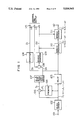
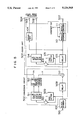
- FIG. 1 is a block diagram showing an arrangement of an efficient coder system used in a first embodiment of the present invention
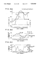
- FIGS. 2(a)-2(c) show exemplary data in a block of one-dimensional array
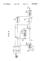
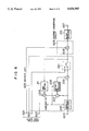
- FIG. 3 is a block diagram showing an arrangement of a decoder system used in the first embodiment
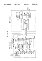
- FIG. 4 is a block diagram showing the arrangements of an efficient coder and its decoder used in a second embodiment of the present invention
- FIG. 5 is a block diagram showing an arrangement of an efficient coder system used in a third embodiment of the present invention.
- FIG. 6 is a block diagram showing an arrangement of a decoder system used in the third embodiment of the present invention.
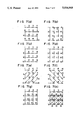
- FIGS. 7(a)-7(h) show diagrams for explaining the sequence of data to be extracted from a block and a predicting method
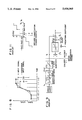
- FIG. 8 is a graph for explaining how to make small the dynamic range of a predictive error
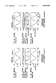
- FIGS. 10(a)-10(d) show examples of operational waveforms of signals appearing (in a normal mode) in the related art MPCM system
- FIG. 11 is a quantizing characteristic in a decoder used in the prior art MPCM system.
- FIGS. 12(a)-12(d) show other examples of operational waveforms of the signals appearing (at the time of generating an anomaly error) in the related art MPCM system.
- a plurality (k) of input data (D1, D2, . . . and Dk) in the vicinity of a sampling position constitute a block as a coding unit
- these differences are small due to the signal correlation and the dynamic range (a difference between the maximum and minimum) of these differences is smaller than the dynamic ranges of the input data in most blocks.
- the difference corresponds to a predictive error when a previous value has been predicted and thus it is hereinafter referred to as the predictive error Si.
- the present invention is intended to carry out coding more efficient than in the prior art, based on the fact that the dynamic range of the predictive error Si is smaller than the dynamic range of input data in most blocks.
- a divisor OU (corresponding to the modulo amplitude in the MPCM system) is defined as a predetermined value which meets the following relationship (2) and uniquely determined by the dynamic range SDR.
- the offset Fi can be uniquely determined because a difference between (Pi+SN-Ei) and (Pi+SX-Ei) is smaller than OU from the definition of OU.
- the data OU ⁇ Ni satisfying the following relationship (8) and the data OU ⁇ Ni satisfying the following relationship (9) correspond respectively to the offset Fi.
- the modulo Ei is a remainder after a division of the input data Di by the divisor data OU, the modulo Ei is zero or larger than zero and smaller than the divisor data OU.
- the word length of the modulo data Ei is determined by the size of divisor data OU and becomes variable depending on the block unit.
- the number of bits necessary for representation of the data OU is expressed as log 2 OU and thus the smaller the data OU is the smaller the necessary bit number is. Since the word length L of modulo data is an integer, however, even when a value smaller than 2 M satisfying the following relationship (10) is used as the divisor data OU, the word length L will not be changed and thus the coding efficiency will not be improved.
- the data SX, SN and OU are necessary at the time of determining the offset Fi necessary for obtaining the data DI from the modulo data Ei, which has been already explained above. It is also similarly possible to transmit, together with modulo data Ei, the data OU and predetermined values SXX and SNN satisfying the following relationships (11) in place of the data SX, SN and OU, and to determine the offset Fi necessary for decoding with us of these data.
- the data SX, SN, SDR, OU, SXX and SNN are information on predictive error and thus will be generally called the predictive error information, hereinafter.
- the predictive error information In three-data combination SX, SN and OU or SXX, SNN and OU, one data can be determined from the remaining two data. Thus, it is only required to directly or indirectly transmit any two of the three data in the combination as the predictive error information.
- the predictive error information (SX, SN and OU) and modulo data obtained through coding operation become equal respectively to the predictive error information and modulo data obtained through the subtraction of a constant value corresponding to a multiple of the divisor data 0U from all the input data Di in each block.
- the predictive error is the same and if the constant value is an integer multiple of the divisor data OU, the modulo data of the remainder after division thereof by the divisor OU is also the same.
- a delay circuit 103 for timing adjustment for delaying input data corresponding to one block by a predetermined time
- a register 104 for holding leading one D1 of data of an output of the delay 103 with respect to each block
- a predictor 105 comprising a register receiving an output of the block divider 102 and for outputting as an estimate Pi an input data previous by one
- modulo encoder 111 for encoding the modulo data Ei according to the size of the divisor data OU, an output terminal 112 of the encoder Ci, a divisor data output terminal 113 of the divisor generator 109, an output terminal 114 for the maximum SX of the predictive errors, and an output terminal 115 for the leading data D1 in a block.
- An input data (having an amplitude level of 0-255 and a word length of 8 bits) in the form of a sampled, quantized video signal is applied to the block divider 102 through the terminal 101.
- the input data D1 firstly extracted from each block is held in the register 104 and then sent out from the terminal 115 as one of additional codes.
- the input data applied to the predictor 105 is converted to the estimate Pi and then supplied from the predictor 105 to the subtracter 106.
- the subtracter 106 subtracts the received estimate Pi from the input data Di and outputs the predictive error Si.
- the maximum/minimum detector 107 receives the predictive errors Si from the subtracter 106 and outputs the maximum SX and minimum SN of the received predictive errors Si in the associated block.
- the subtracter 108 receives the maximum SX and minimum SN from the detector 107, performs a subtraction thereof and outputs the predictive error dynamic range SDR.
- the dynamic range SDR is sent from the subtracter 108 to the divisor generator 109 and outputs the divisor data OU which satisfies the following relationship (10).
- the divisor data OU and the predictive error maximum SX as the predictive error information are output from the terminals 113 and 114 respectively as one of additional codes.
- Shown in FIG. 2 are examples of the input data Di, offset Fi, predictive error Si and modulo data Ei when one block is constituted by 16 picture elements in horizontal direction and one line in vertical direction.
- 16 input data in this block are the data D1, 112, 105, 113, 121, 136, 160, 175, 201, 207, 208, 199, 193, 176, 169, 178 and 190 and extracted in the sequential order from the data D1.
- the order of data to be extracted from a block of two-dimensional configuration and how to predict will be described later.
- Allowable upper and lower limits of the maximums SX in the generated predictive errors are 255 and -255 respectively and similarly allowable upper and lower limits of the minimums SN in the generated predictive errors are 255 and -255 respectively, so that the word length of the maximum and minimum predictive errors SX and SN must be 9 bits.
- the upper and lower limits of the predictive error dynamic range SDR are 510 and 0 respectively and thus the word length of the dynamic range SDR must be 9 bits.
- the divisor data OU also must have a word length of 9 bits. In the present embodiment, however, since the divisor data OU is set to be 2 M satisfying the relationship (10), the divisor data OU can be expressed with a word length of a less number of bits.
- the divisor data OU in place of directly transmitting the divisor data OU, it is only required to transmit a power M in 2 M .
- the power M can assume one of 0, 1, 2, . . . , and 9 and thus the word length of the divisor data OU can be only 4 bits.
- the divisor data OU can be transmitted in the form of a 4-bit code M.
- the divisor data OU is uniquely defined by the predictive error dynamic range SDR so that the divisor generator 109 can comprise a ROM (read only memory) having 9 bit inputs and 4 bit outputs. However, since the divisor data OU is set to be 2 M , the divisor generator 109 may also comprise a simple logical circuit which detects the number of successive 0s in the bits of the data indicative of the dynamic range SDR from its uppermost bit.
- the modulo operator 110 for obtaining the modulo data Ei corresponding to the remainder after the division of the input data by the divisor data OU may also comprise, in general, a divider or a ROM.
- the modulo encoder 111 which encodes modulo data Ei in terms of the bit number J determined by the size of the divisor data OU, can realize with a simple circuit which extracts only lower J bits from the modulo data Ei and which stops the output of the other unnecessary upper bits.
- the output format of the encoded codes Ci may be considered in various ways, the encoded codes Ci are output on a serial data basis in the present embodiment.
- the output signals of the coder that is, the additional codes (D1, SX and OU) and the encoded codes (C2, C3, . . . , and C16) are once stored in a buffer memory and after completion of coding processing or the like for error correction, they are output onto a transmission line, for example, on a serial data basis.
- the divisor data OU is 64 and thus the word length J of the code Ci becomes 6.
- the total output bit number CD of the coder in this block is 111 ( ⁇ 128) in accordance with the equation (13) and the average bit number per one sample is reduced to about 6.9.
- FIG. 3 shows a block diagram showing the arrangement of a decoder used in the first embodiment of the present invention, which decoder performs inverse transformation opposed to in the coder of FIG. 1.
- data treated in the decoder are shown with an apostrophe to distinguish them from data treated in the coder.
- input data D1, D2, . . . , D16 in the block to the coder are encoded, and the decoder decodes this data and outputs the data as D1', D2', . . . , D16'.
- the decoder of FIG. 3 includes an input terminal 201 for input of the codes Ci, an input terminal 202 for input of the divisor data OU, an input terminal 203 for input of the maximum predictive error SX, an input terminal 204 for input of the leading data D1 in each block, a modulo decoder 205 for performing inverse transformation opposite to in the modulo encoder 111 used in the efficient coder of FIG.
- the input data D1 applied to, the terminal 204 passes through switch 210 and and is supplied the block resolver 212 and also to the predictor 211 as decoded data D1'.
- the data D1' is used, in the predictor 211, as an estimate P2' which is necessary for calculating the decoded data from the initial modulo data E2'.
- the switch 210 after outputting the input data D1, selects the input from the offset adder 209 and outputs the decoded data D2', D3', . . . , and D16'.
- the subtracter 207 subtracts the modulo data Ei' from the received addition result to obtain a data (Pi'+SX-Ei').
- the decoded data Di' applied to the block resolver 212 are extracted in the same order as the data obtained by sampling and quantizing the original video signal and are output from the terminal 213.
- the divisor data OU is set to be 2 M , so that the offset Fi' can be obtained only by setting all the lower M bits of the data (Pi'+SX-Ei') at 0.
- the offset reproducer 208 can be realized with use of a simple logical circuit.
- the offset Fi' is also equal to the offset Fi and the decoded data Di' coincides with the input data Di.
- the modulo data is transmitted as coded as it is, the divisor data OU (modulo amplitude in the MPCM system) ar set to be larger than the predictive error variation range (dynamic range), and further the divisor data OU and the information on the predictive error variation range are transmitted as the additional codes.
- the divisor data OU modulo amplitude in the MPCM system
- the predictive error variation range dynamic range
- the divisor data OU and the information on the predictive error variation range are transmitted as the additional codes.
- the divisor data (modulo amplitude) in the coding operation has been fixed or set to be a maximum of absolute values of predictive errors; whereas, in the present invention, the divisor data is determined by the predictive error variation range (dynamic range) so that the divisor in the coding operation can be made smaller than that in the prior art. Accordingly, in particular, in a block in which an input data is monotonously increased or decreased, coding can be realized more efficiently than the prior art. In the case where a video signal is used as an input signal, since rough picture image can be reproduced with use of only a part (the leading picture element data of the block) of the additional codes, so that coding suitable also for picture research can be realized.
- the ninth input data can be corrected with use of an average value of the eighth and tenth decoded data.
- the block of FIG. 2 has been of one-dimensional configuration.
- the block is of two- or higher-dimensional configuration as in a video signal, such correction can be attained with use of decode data within a plurality of surrounding blocks.
- a transmission error takes place in the additional codes indicative of the predictive error information
- There is also considered such a coding method that one of the adjacent blocks to be suitably used in correction is previously determined at the time of occurrence of a transmission error and this information is transmitted as one of the additional codes, in which case more suitable correction can be realized.
- the simplest way of obtaining the converted input signal is to multiply the input signal by a predetermined number for each block.
- the input signal is multiplied by the predetermined number smaller than 1, the converted input signal having the smaller dynamic range can be obtained and the predictive error dynamic range of the converted input signal can be made smaller by substantially the predetermined number than the predictive error dynamic range of the input signal. This is because the processing of obtaining the predictive errors is linear.
- FIG. 4 there are shown, in a block diagram form, a coding and decoding system in accordance with a second embodiment of the present invention.
- the coding system functions to make constant the number of coding bits for each block.
- the encoder system 402 has a block divider (which is the same as the block divider 102 in FIG. 1), coefficient appliers 405, 406, 407 and 408 multiplying the input signal by coefficients 1/2, 1/4, 1/8 and 1/16 respectively, coders 409, 410, 411 and 412 respectively having the same internal configuration as in FIG.
- a detector 413 for receiving from the coders 409 to 412 divisor data OU respectively indicative of the word length of the encoded code that is one of the additional code outputs of each of the coders 409 to 412 and for outputting conversion information
- a switch 414 for receiving outputs of the coders 409 to 412 and an output of the coefficient applier 408 and the conversion information from the detector 413 and, under control of the received conversion information, for selectively outputting, if present, one of the outputs of the coders 409 to 412 which reaches 4 bits in its encoded data word length and for selectively outputting, if not present, the output of the coefficient applier 408.
- the decoder system 403 has a block resolver 212 (which is the same as the block resolver 212 in FIG. 3), a decoder 415 having the same internal arrangement as in FIG. 3 but with the block resolver 212 being removed, a switch 416 for receiving an output of the decoder 415 and one of the encoded codes from the switch 414 and for outputting one of the received inputs under control of the conversion information transmitted from the detector 413, a switch 417 for selectively outputting one of predetermined coefficients under control of the conversion information transmitted from the detector 413, and a multiplier 418 for multiplying the reproduced conversion signal from the switch 416 by the selected predetermined coefficient received from the switch 417 for reproduction of the input signal.
- the switch 414 is controlled by the output of the detector 413 to selectively output one of the encoded codes which becomes 4 bits in word length.
- the switch 414 if failing to detect any of the coders which becomes 4 bits in word length, selects the output of the coefficient applier 408 and outputs it as an encoded code as it is. Since it is necessary to transmit information (3 bits) to the decoder 403 to inform the decoder of one of the conversion input signals which has been encoded and transmitted, the information as the conversion information is included in the additional codes and transmitted. Assume that the lower limit value of the word lengths of the encoded codes is set to be 4 bits in the coder 409.
- the amount of information to be transmitted becomes a total of 80 bits, that is, 3 bits of conversion information for the additional codes, 8 bits (at least) of block leading data, a maximum of 9 bits (at least) of predictive error and 4 ⁇ 15 bits of encoded codes.
- the number of bits per one picture element becomes 5 bits in average.
- the decoder 415 decodes the encoded data transmitted from the encoder system 402 to decode the conversion input signal in the encoder system without any error.
- the decoded conversion input signal from the decoder 415 is applied through the switch 416 to the multiplier 418 as its one input.
- the switch 417 selects and outputs one of the inverse conversion coefficients under control of the conversion information transmitted from the detector 413 for conversion of the decoded conversion input signal into the input signal.
- the multiplier 418 multiplies the conversion input signal by the selected inverse conversion coefficient received from the switch 417 to convert it into the input signal.
- the reproduced block input signal is resolved at the block resolver 212 so that a signal having the same data array as the input signal of the block divider 102 is output from the block resolver to the terminal 404.
- the transmitted encoded data is determined to be the output of the coefficient applier 408 on the basis of the transmitted conversion information, since the encoded data corresponds to the conversion input signal per se, the encoded data is not passed through the decoder 415 and applied to the multiplier 418 through the switch 416.
- the input signal when it is impossible, in encoding the input signal, to encode the input signal with the predetermined encode data word length, the input signal is multiplied by the predetermined coefficient to form the conversion input signal having a small predictive error dynamic range and then the obtained conversion input signal is encoded, whereby the encode data word length can be made constant. Since the coding operation of the conversion signal is the same as that of the first embodiment, that is, information preserving coding, no anomaly errors take place.
- the input signal is large in predictive error dynamic range
- the input signal is multiplied by the predetermined coefficient to be converted into the conversion input signal, which is then encoded, so that quantization becomes rough.
- Large ones of the predictive errors in the dynamic range mean sharply varying points (acute points) in the input signal.
- the sharply varying points in the signal even when the quantization is rough, is immune to the signal deterioration, which results in that practical coding matching visual characteristics can be realized.
- FIG. 5 Shown by a block diagram in FIG. 5 is a coder system in a third embodiment of the present invention, which system includes an input terminal 501 for input of a sampled, quantized video signal as an input signal, a block divider 102 (which is the same as the block divider 102 in FIG.
- a conversion circuit 502 for generating conversion information and conversion coefficients, multiplying the input signal by the conversion coefficients to form a conversion input signal and then outputting the conversion input signal, a coder unit 503, an output terminal 504 for the conversion information (inverse conversion coefficient 1/a), an output terminal 505 for a leading data d 1 within a block of the conversion input signal, an output terminal 506 for a maximum sx of predictive errors for conversion input data, and an output terminal 507 for encoded data c 1 .
- the conversion circuit 502 includes a delay 508, a predictor 509, a subtracter 510, a maximum/minimum detecting circuit 511, a conversion information generating circuit 512 for receiving the maximum and minimum predictive errors from the maximum/minimum detector 511 and for outputting, on the basis of the received maximum and minimum, the conversion information (conversion coefficient a and inverse conversion coefficient 1/a) for generation of the conversion input signal, a multiplier 513 for multiplying an input signal from the delay 508 by the conversion coefficient from the conversion information generator 512, these elements 508, 509, 510 and 511 being the same as the associated elements 103, 105, 106 and 107 respectively.
- the coder unit 503 includes a delay 103, a register 104, a predictor 105, a subtracter 106, a modulo operator 110, a modulo encoder 111, and a maximum/minimum detecting circuit 514 for detecting a maximum of predictive errors received from the subtracter 106 for each block, holding the maximum in its internal register and outputting it for each block.
- the sampled, quantized video signal applied to the terminal 501 as an input data is supplied to the block divider 102 where the input signal is divided on a block unit data basis into block signals.
- the conversion circuit 502 receives the block signal, multiplies it by the fixed conversion coefficient a for each block, and rounds the multiplied signal with respect to its fractional part to form the conversion input signal. How to determine the conversion coefficient a will be explained later.
- the coder unit 503 receives the conversion input signal from the conversion circuit 502 and encodes it in the same manner as in the first embodiment (FIG. 1) of the present invention. That is, the conversion input signal is previously subjected at the conversion circuit 502 to such conversion that the coder unit 503 enables information preserving coding of the conversion input signal with a fixed word length of L bits. Thus, it is unnecessary to newly find the divisor data OU. For this reason, the coder unit 503 has the same arrangement as the coder system of FIG. 1 but with the subtracter 108 and the divisor generator 109 being removed. Further, the conversion input signal is already a block signal and thus the block divider 102 is also removed in the coder unit 503.
- the coder unit 503 outputs the maximum SX of predictive errors and the leading data d 1 in each block for the conversion input signal and the encoded codes.
- the conversion information (inverse conversion coefficient 1/a) is necessary for the purpose of inversely converting into the original input signal the conversion input signal encoded and transmitted, the conversion information is transmitted as one of the additional codes.
- the conversion coefficient a is determined as follows. That is, in the conversion circuit 502, a difference between the output of the predictor 509 and the input signal, i.e., a predictive error is computed by the subtracter 510.
- the maximum/minimum detecting circuit 511 computes and outputs the maximum SX and minimum SN of predictive errors for each block of the input signal. This results in that the predictive error dynamic range SDR of the input signal becomes (SX-SN).
- the predictive error dynamic range SDR of the conversion input signal can be set to be (2 L -1) and efficient coding can be realized.
- the conversion coefficient a is set to be smaller than (2 L -1)/(SX-SN).
- the conversion information generating circuit 512 is set to generate the conversion coefficient a satisfying the following relationship (15).
- the conversion information generator 512 can be easily realized by a ROM (read only memory) which stores therein the previously computed conversion coefficient a satisfying the relationship (15).
- ROM read only memory
- FIG. 6 shows, in a block diagram form, a decoding system in the third embodiment of the present invention, which functions to perform inverse transformation opposite to the coding system of FIG. 5.
- the decoding system of FIG. 6 includes an input terminal 601 for input of the conversion information (inverse conversion coefficient 1/a), an input terminal 602 for input of the leading data d 1 in a block of the conversion input signal, an input terminal 603 for input of the maximum sx of predictive errors for the conversion input data, a decoder unit 605 for the conversion input signal transmitted from the coder system, an inverse conversion circuit 606 for performing inverse conversion of a decoded conversion input signal into the original input signal, a block resolver 212 for resolving a block into reproduced block input signals and for converting the block input signals for blocks into a signal (reproduced input signal) having the same data array as the original input signal, and an output terminal 607 for output of the reproduced input signal.
- the conversion information inverse conversion coefficient 1/a
- an input terminal 602 for input of the leading data d 1 in a block of the conversion input signal
- an input terminal 603 for input of the maximum sx of predictive errors for the conversion input data
- the decoder unit 605 has a modulo decoder 205, an adder 206, a subtracter 207, an offset reproducer 208, an adder 209, and a switch 210.
- the inverse converter 606 has a multiplier 608.
- the decoder unit 605 has basically the same arrangement as the decoder unit of FIG. 3, except that the divisor data OU is not input because the data OU is constant and it is unnecessary to transmit the data OU, so that the decoder unit 605 decodes the encoded data into the original conversion input signal with use of the transmitted additional codes.
- the conversion input signal is multiplied at the inverse conversion circuit 606 multiplied by the transmitted inverse conversion coefficient 1/a (conversion information) to form the original block input signal.
- the block input signal is then sent to the block resolver 212 to be converted to a signal having the same data array as the original input signal of the coder system. Then the output of the block resolver 212 is output from the terminal 607.
- the input signal is multiplied by the conversion coefficient a to obtain the conversion input signal and the conversion input signal is subjected to the information preserving coding of the first embodiment of FIG. 1. Since the predictive error dynamic range of the input signal is proportional to the predictive error dynamic range of the conversion input signal when the influences of the rounding error is ignored, the predictive error dynamic range of the input signal is first computed and the conversion coefficient a is set so that the predictive error dynamic range of the conversion input signal does not exceed the dynamic range determined by the word length of the encoded data and also close thereto, which results in that coding can be efficiently realized.
- the conversion coefficient is set, taking the rounding error into consideration, so as no to exceed the upper limit of the dynamic range, the conversion input signal can be subjected to the information preserving coding and no anomaly errors will take place.
- the distortion of the input signal through the coding and decoding operation is caused only by the word length limitation and rounding error by the conversion coefficient multiplication in conversion of the input signal to the conversion input signal and in its inverse conversion.
- an average word length of the encoded codes may be set constant for every predetermined-number blocks.
- coding is carried out with an average word length of 4 bits for every 2 blocks.
- two blocks A and B have 6 and 4 bits respectively and allow information preserving coding, coding can be realized without any deterioration because of 4 bits of average encoding word length.
- the word lengths of the encoded codes for each block are all fixed to be 4 bits, the block A produces signal deterioration corresponding to 2 bits and a space corresponding to 2 bits/sample is produced in the block. Accordingly, when the transmission rate is set to be constant and coding is carried out for ever plural blocks, coding efficiency can be improved when compared with that of coding for every block.
- the following is an example of how to determine the number of bits with which each block in the encoding unit is encoded.
- the predictive error dynamic range is computed for all the blocks in the encoding unit to find the average bit number of the encoded codes in the information preserving coding operation. Conversion is carried out so that the predictive error dynamic range of the input signal for each block is small in average by a bit number corresponding to a difference between the found bit number and the actual bit number.
- the abovementioned coding system can be realized only by adding to the coding system of FIG. 5 a means for computing an average encoding bit number when it is assumed to perform information preserving coding with respect to a buffer memory corresponding to the illustrated encoding unit, and a means for computing a difference between the computed average encoding bit number and the actual encoding bit number and storing the difference.
- This decoder system is basically the same as the decoder system of FIG. 6 and thus explanation thereof is omitted.
- the encoded data dynamic range is not fully efficiently utilized, because some allowance is provided so that, even when the predictive error dynamic range is expanded by the rounding error, this causes the predictive error dynamic range not to exceed the encoded data dynamic range.
- FIG. 8 As a method of reducing the predictive error dynamic range, there is considered such a method that non-linear conversion is carried out as shown in FIG. 8.
- white and black dots EP denote input signals before and after its conversion respectively.
- the maximum sx of predictive errors for the conversion input signal is 2-levels smaller than the maximum SX.
- the predictor in the coding system is a sort of low pass filter
- the predictive errors can be regarded as the high frequency components of the input signal.
- a high frequency suppressing filter can be considered to reduce the predictive error dynamic range.
- a filter having a characteristic opposite to the high frequency suppressing filter is used.
- codes indicative of the presence or absence of the filter or the characteristic thereof can be considered.
- the block may have a one-dimensional configuration (for example, 16 picture elements in horizontal direction and one line in vertical direction), a two-dimensional configuration (for example, 4 picture elements in horizontal direction and 4 lines in vertical direction), or a three-dimensional configuration extended between fields and frames.
- a one-dimensional configuration for example, 16 picture elements in horizontal direction and one line in vertical direction
- a two-dimensional configuration for example, 4 picture elements in horizontal direction and 4 lines in vertical direction
- a three-dimensional configuration extended between fields and frames extended between fields and frames.
- a block consists of input data corresponding to sample positions continuous in horizontal or vertical direction, but the present invention is not limited to the particular configuration so long as a block consists of a plurality of strongly correlative input data.
- a block can also consist of input data corresponding to the sample positions of equiphase points.
- a signal providing a highest coding efficiency is such a signal that monotonously increases or decreases, because the predictive error dynamic range is smallest. Accordingly, there can be considered such a method that a plurality of different orders of input data to be extracted from the block are prepared and one of the orders which provides a smallest predictive error dynamic rang is selected. In this case, a code indicative of the input-data extracting method (a sort of predicting method) is transmitted as one of the additional codes.
- an interpolation prediction may also be employed.
- the first embodiment in which only the leading input data in each block is not encoded and transmitted as it is, so that a value obtained through linear interpolation with use of the leading data of each block is used as a predicted value and a difference between input data is used as a predictive error.
- the interpolation prediction unlike the extrapolation prediction, a sequentally decoded data is not used in prediction of the next data and thus no erroneous transmission takes place.
- an efficient coding method and its decoding method which enable efficient transmission without any anomaly errors with use of a simple arrangement, finding its practically useful applications.
Landscapes
- Engineering & Computer Science (AREA)
- Theoretical Computer Science (AREA)
- Compression, Expansion, Code Conversion, And Decoders (AREA)
- Compression Or Coding Systems Of Tv Signals (AREA)
Applications Claiming Priority (2)
| Application Number | Priority Date | Filing Date | Title |
|---|---|---|---|
| JP63-286145 | 1988-11-11 | ||
| JP28614588 | 1988-11-11 |
Publications (1)
| Publication Number | Publication Date |
|---|---|
| US5034965A true US5034965A (en) | 1991-07-23 |
Family
ID=17700519
Family Applications (1)
| Application Number | Title | Priority Date | Filing Date |
|---|---|---|---|
| US07/433,341 Expired - Fee Related US5034965A (en) | 1988-11-11 | 1989-11-08 | Efficient coding method and its decoding method |
Country Status (3)
| Country | Link |
|---|---|
| US (1) | US5034965A (de) |
| EP (1) | EP0369682B1 (de) |
| DE (1) | DE68925516T2 (de) |
Cited By (17)
| Publication number | Priority date | Publication date | Assignee | Title |
|---|---|---|---|---|
| US5241385A (en) * | 1991-03-11 | 1993-08-31 | Zenith Electronics Corporation | Television signal transmission system with carrier offset compensation |
| US5392037A (en) * | 1991-05-21 | 1995-02-21 | Matsushita Electric Industrial Co., Ltd. | Method and apparatus for encoding and decoding |
| US5497129A (en) * | 1994-06-27 | 1996-03-05 | General Motors Corporation | Filter elements having ferroelectric-ferromagnetic composite materials |
| US5497338A (en) * | 1993-04-09 | 1996-03-05 | Sharp Kabushiki Kaisha | Motion vector detecting circuit |
| US5519394A (en) * | 1994-01-11 | 1996-05-21 | Fujitsu Limited | Coding/decoding apparatus and method |
| US5533052A (en) * | 1993-10-15 | 1996-07-02 | Comsat Corporation | Adaptive predictive coding with transform domain quantization based on block size adaptation, backward adaptive power gain control, split bit-allocation and zero input response compensation |
| US5703889A (en) * | 1991-06-04 | 1997-12-30 | Kabushiki Kaisha Toshiba | High efficiency coding signal processing apparatus with error propagation influence reduction |
| RU2214047C2 (ru) * | 1997-11-19 | 2003-10-10 | Самсунг Электроникс Ко., Лтд. | Способ и устройство для масштабируемого кодирования/декодирования аудиосигналов |
| US6714147B2 (en) * | 2001-08-21 | 2004-03-30 | Deutsche Telekom Ag | Method for compressing data |
| US20050226352A1 (en) * | 2002-05-07 | 2005-10-13 | Kasperkovitz Wolfdietrich G | Mirror suppression circuit and receiver using such circuit |
| US20060146930A1 (en) * | 2005-01-05 | 2006-07-06 | Samsung Electronics Co., Ltd. | Method and apparatus for encoding and decoding image data |
| US20070171104A1 (en) * | 2006-01-17 | 2007-07-26 | Harmonic Drive Systems Inc. | Apparatus for transmitting position detection signal of multi-shaft motor |
| US20100054330A1 (en) * | 2004-01-30 | 2010-03-04 | Tao Chen | Picture coding method, picture decoding method, picture coding apparatus, picture decoding apparatus, and program thereof |
| US7912122B2 (en) | 2004-01-20 | 2011-03-22 | Panasonic Corporation | Picture coding method, picture decoding method, picture coding apparatus, picture decoding apparatus |
| US7933327B2 (en) | 2004-01-30 | 2011-04-26 | Panasonic Corporation | Moving picture coding method and moving picture decoding method |
| US20140062776A1 (en) * | 2009-02-20 | 2014-03-06 | Trimble Navigation Limited | Ambiguity Windowing in Communications Among Global Navigation System Satellite Receivers |
| US20160127746A1 (en) * | 2012-05-04 | 2016-05-05 | Environmental Systems Research Institute, Inc. | Limited error raster compression |
Families Citing this family (7)
| Publication number | Priority date | Publication date | Assignee | Title |
|---|---|---|---|---|
| TW241350B (de) * | 1991-11-07 | 1995-02-21 | Rca Thomson Licensing Corp | |
| KR100368854B1 (ko) * | 1993-06-30 | 2003-05-17 | 소니 가부시끼 가이샤 | 디지털신호의부호화장치,그의복호화장치및기록매체 |
| TW272341B (de) * | 1993-07-16 | 1996-03-11 | Sony Co Ltd | |
| DE69427222T2 (de) * | 1993-10-08 | 2001-08-30 | Sony Corp., Tokio/Tokyo | Digitaler signalprozessor, verfahren zum verarbeiten digitaler signale und medium zum aufnehmen von signalen |
| US5635930A (en) * | 1994-10-03 | 1997-06-03 | Sony Corporation | Information encoding method and apparatus, information decoding method and apparatus and recording medium |
| TW383508B (en) | 1996-07-29 | 2000-03-01 | Nichia Kagaku Kogyo Kk | Light emitting device and display |
| WO2013088721A1 (ja) * | 2011-12-13 | 2013-06-20 | 株式会社Jvcケンウッド | 動画像符号化装置、動画像符号化方法及び動画像符号化プログラム、並びに動画像復号装置、動画像復号方法及び動画像復号プログラム |
Citations (4)
| Publication number | Priority date | Publication date | Assignee | Title |
|---|---|---|---|---|
| US4571737A (en) * | 1982-12-10 | 1986-02-18 | Nec Corporation | Adaptive differential pulse code modulation decoding circuit |
| US4791485A (en) * | 1983-06-16 | 1988-12-13 | Nippon Telegraph & Telephone Public Corporation | System for detecting a transmission error |
| US4792954A (en) * | 1986-10-31 | 1988-12-20 | International Business Machines Corporation | Concurrent detection of errors in arithmetic data compression coding |
| US4933762A (en) * | 1987-12-16 | 1990-06-12 | Etat Francais represente par le Ministre des Postes et Telecommunications et de l'Espace (Centre National d'Etudes des Telecommunications) | Method and coding and decoding devices for picture transmission through a variable rate network |
-
1989
- 1989-11-08 US US07/433,341 patent/US5034965A/en not_active Expired - Fee Related
- 1989-11-09 EP EP89311610A patent/EP0369682B1/de not_active Expired - Lifetime
- 1989-11-09 DE DE68925516T patent/DE68925516T2/de not_active Expired - Fee Related
Patent Citations (4)
| Publication number | Priority date | Publication date | Assignee | Title |
|---|---|---|---|---|
| US4571737A (en) * | 1982-12-10 | 1986-02-18 | Nec Corporation | Adaptive differential pulse code modulation decoding circuit |
| US4791485A (en) * | 1983-06-16 | 1988-12-13 | Nippon Telegraph & Telephone Public Corporation | System for detecting a transmission error |
| US4792954A (en) * | 1986-10-31 | 1988-12-20 | International Business Machines Corporation | Concurrent detection of errors in arithmetic data compression coding |
| US4933762A (en) * | 1987-12-16 | 1990-06-12 | Etat Francais represente par le Ministre des Postes et Telecommunications et de l'Espace (Centre National d'Etudes des Telecommunications) | Method and coding and decoding devices for picture transmission through a variable rate network |
Non-Patent Citations (10)
| Title |
|---|
| M. Hagiwara and M. Nakagawa, "A New Decoder for Modulo-PCM", in the VIII-th Symposium on Information Theory and its Applications, Nara, Japan, Dec., 5-7, 1985, pp. 517-522. |
| M. Hagiwara and M. Nakagawa, A New Decoder for Modulo PCM , in the VIII th Symposium on Information Theory and its Applications, Nara, Japan, Dec., 5 7, 1985, pp. 517 522. * |
| Mizui, et al., "Variable Bit Rate Modulo-PCM Using Adaptive Prediction", IEEE International Conference on Communications '88, vol. 2/3, pp. 652-656, Jun. 12, 1988. |
| Mizui, et al., Variable Bit Rate Modulo PCM Using Adaptive Prediction , IEEE International Conference on Communications 88, vol. 2/3, pp. 652 656, Jun. 12, 1988. * |
| T. Ericson & V. Ramamoorthy, "Modulo-PCM: A New Source Coding Scheme", In Conf., Int. Conf. Acoust., Speech, Signal Processing, ICASSP '79, Sachington, DC, 1979, pp. 419-422. |
| T. Ericson & V. Ramamoorthy, Modulo PCM: A New Source Coding Scheme , In Conf., Int. Conf. Acoust., Speech, Signal Processing, ICASSP 79, Sachington, DC, 1979, pp. 419 422. * |
| V. Ramamoorthy, "A Novel Speech Coder for Medium and High Bit Rate Application Using Modulo-PCM Principles", IEEE Trans. Acoust., Speech, Signal Processing, vol. ASSP33, pp. 356-368, Apr. 1985. |
| V. Ramamoorthy, "Speech Coding Using Modulo-PCM with Side Information", In Conf. Rec., Int. Conf. Acoust., Speech, Signal Processing, ICASSP '81, Atlanta, GA, Mar. 1981, pp. 832-835. |
| V. Ramamoorthy, A Novel Speech Coder for Medium and High Bit Rate Application Using Modulo PCM Principles , IEEE Trans. Acoust., Speech, Signal Processing, vol. ASSP33, pp. 356 368, Apr. 1985. * |
| V. Ramamoorthy, Speech Coding Using Modulo PCM with Side Information , In Conf. Rec., Int. Conf. Acoust., Speech, Signal Processing, ICASSP 81, Atlanta, GA, Mar. 1981, pp. 832 835. * |
Cited By (34)
| Publication number | Priority date | Publication date | Assignee | Title |
|---|---|---|---|---|
| US5241385A (en) * | 1991-03-11 | 1993-08-31 | Zenith Electronics Corporation | Television signal transmission system with carrier offset compensation |
| US5392037A (en) * | 1991-05-21 | 1995-02-21 | Matsushita Electric Industrial Co., Ltd. | Method and apparatus for encoding and decoding |
| US5703889A (en) * | 1991-06-04 | 1997-12-30 | Kabushiki Kaisha Toshiba | High efficiency coding signal processing apparatus with error propagation influence reduction |
| US5497338A (en) * | 1993-04-09 | 1996-03-05 | Sharp Kabushiki Kaisha | Motion vector detecting circuit |
| US5533052A (en) * | 1993-10-15 | 1996-07-02 | Comsat Corporation | Adaptive predictive coding with transform domain quantization based on block size adaptation, backward adaptive power gain control, split bit-allocation and zero input response compensation |
| US5519394A (en) * | 1994-01-11 | 1996-05-21 | Fujitsu Limited | Coding/decoding apparatus and method |
| US5497129A (en) * | 1994-06-27 | 1996-03-05 | General Motors Corporation | Filter elements having ferroelectric-ferromagnetic composite materials |
| RU2214047C2 (ru) * | 1997-11-19 | 2003-10-10 | Самсунг Электроникс Ко., Лтд. | Способ и устройство для масштабируемого кодирования/декодирования аудиосигналов |
| US6714147B2 (en) * | 2001-08-21 | 2004-03-30 | Deutsche Telekom Ag | Method for compressing data |
| US20050226352A1 (en) * | 2002-05-07 | 2005-10-13 | Kasperkovitz Wolfdietrich G | Mirror suppression circuit and receiver using such circuit |
| US7242730B2 (en) * | 2002-05-07 | 2007-07-10 | Semiconductor Ideas To Market, B.V. | Mirror suppression circuit and receiver using such circuit |
| US7912122B2 (en) | 2004-01-20 | 2011-03-22 | Panasonic Corporation | Picture coding method, picture decoding method, picture coding apparatus, picture decoding apparatus |
| US7995650B2 (en) | 2004-01-20 | 2011-08-09 | Panasonic Corporation | Picture coding method, picture decoding method, picture coding apparatus, picture decoding apparatus, and program thereof |
| US20110110423A1 (en) * | 2004-01-20 | 2011-05-12 | Shinya Kadono | Picture coding method, picture decoding method, picture coding apparatus, picture decoding apparatus, and program thereof |
| US7933327B2 (en) | 2004-01-30 | 2011-04-26 | Panasonic Corporation | Moving picture coding method and moving picture decoding method |
| US8218623B2 (en) | 2004-01-30 | 2012-07-10 | Panasonic Corporation | Moving picture coding method and moving picture decoding method |
| USRE49787E1 (en) | 2004-01-30 | 2024-01-02 | Dolby International Ab | Moving picture coding method and moving picture decoding method |
| USRE48401E1 (en) | 2004-01-30 | 2021-01-19 | Dolby International Ab | Moving picture coding method and moving picture decoding method |
| US20110150082A1 (en) * | 2004-01-30 | 2011-06-23 | Jiuhuai Lu | Moving picture coding method and moving picture decoding method |
| US20110150083A1 (en) * | 2004-01-30 | 2011-06-23 | Jiuhuai Lu | Moving picture coding method and moving picture decoding method |
| USRE46500E1 (en) | 2004-01-30 | 2017-08-01 | Dolby International Ab | Moving picture coding method and moving picture decoding method |
| US8477838B2 (en) | 2004-01-30 | 2013-07-02 | Panasonic Corporation | Moving picture coding method and moving picture decoding method |
| US8194734B2 (en) | 2004-01-30 | 2012-06-05 | Panasonic Corporation | Moving picture coding method and moving picture decoding method |
| US20100054330A1 (en) * | 2004-01-30 | 2010-03-04 | Tao Chen | Picture coding method, picture decoding method, picture coding apparatus, picture decoding apparatus, and program thereof |
| US8396116B2 (en) | 2004-01-30 | 2013-03-12 | Panasonic Corporation | Moving picture coding method and moving picture decoding method |
| US8401074B2 (en) | 2004-01-30 | 2013-03-19 | Panasonic Corporation | Picture coding method, picture decoding method, picture coding apparatus, picture decoding apparatus, and program thereof |
| US7995848B2 (en) * | 2005-01-05 | 2011-08-09 | Samsung Electronics Co., Ltd. | Method and apparatus for encoding and decoding image data |
| US20060146930A1 (en) * | 2005-01-05 | 2006-07-06 | Samsung Electronics Co., Ltd. | Method and apparatus for encoding and decoding image data |
| US20070171104A1 (en) * | 2006-01-17 | 2007-07-26 | Harmonic Drive Systems Inc. | Apparatus for transmitting position detection signal of multi-shaft motor |
| US7348897B2 (en) * | 2006-01-17 | 2008-03-25 | Harmonic Drive Systems Inc. | Apparatus for transmitting position detection signal of multi-shaft motor |
| US20140062776A1 (en) * | 2009-02-20 | 2014-03-06 | Trimble Navigation Limited | Ambiguity Windowing in Communications Among Global Navigation System Satellite Receivers |
| US9354319B2 (en) * | 2009-02-20 | 2016-05-31 | Trimble Navigation Limited | Ambiguity windowing in communications among global navigation system satellite receivers |
| US20160127746A1 (en) * | 2012-05-04 | 2016-05-05 | Environmental Systems Research Institute, Inc. | Limited error raster compression |
| US9819964B2 (en) * | 2012-05-04 | 2017-11-14 | Environmental Systems Research Institute, Inc. | Limited error raster compression |
Also Published As
| Publication number | Publication date |
|---|---|
| EP0369682A3 (de) | 1991-05-02 |
| DE68925516T2 (de) | 1996-09-12 |
| EP0369682A2 (de) | 1990-05-23 |
| EP0369682B1 (de) | 1996-01-24 |
| DE68925516D1 (de) | 1996-03-07 |
Similar Documents
| Publication | Publication Date | Title |
|---|---|---|
| US5034965A (en) | Efficient coding method and its decoding method | |
| US4672441A (en) | Method and apparatus for picture data reduction for digital video signals | |
| US4816914A (en) | Method and apparatus for efficiently encoding and decoding image sequences | |
| US5045852A (en) | Dynamic model selection during data compression | |
| US7206448B2 (en) | System and method for using pattern vectors for video and image coding and decoding | |
| US4866510A (en) | Digital video encoder | |
| US6654503B1 (en) | Block-based, adaptive, lossless image coder | |
| US4851906A (en) | Data compression using orthogonal transform and vector quantization | |
| US6411231B1 (en) | Encoding, decoding, and probability estimation method | |
| EP0734174A2 (de) | Verfahren zur adaptiver Komprimierung von digitalen Restbilddaten in einem DPCM-Kompressionssystem | |
| US4005411A (en) | Compression of gray scale imagery to less than one bit per picture element | |
| US6121904A (en) | Lossless data compression with low complexity | |
| JPS5921039B2 (ja) | 適応予測符号化方式 | |
| JP2000125297A (ja) | 連続画像の符号化方法及び復号化方法 | |
| US6118392A (en) | Lossless data compression with low complexity | |
| CA1219373A (en) | Adaptive differential pulse code modulation decoding circuit | |
| KR930009436B1 (ko) | 파형부호화/복호화 장치 및 방법 | |
| JP2005524300A (ja) | コードワードインデックスに対してパラメータ値のマッピングを行うための適応型方法およびシステム | |
| US4498173A (en) | Technique for digital split-channel transmission using interpolative coders and decoders | |
| KR20040075944A (ko) | 디지털 정보신호의 데이터 압축 및 압축해제 | |
| US4905002A (en) | Delta modulation encoder/decoder method and system | |
| JPH04343576A (ja) | 高能率符号化方法と高能率符号の復号方法 | |
| JP2794842B2 (ja) | 符号化方法とその復号化方法 | |
| JP4415651B2 (ja) | 画像符号化装置、及び画像復号化装置 | |
| JPS62239693A (ja) | デイジタル画像信号のデ−タ整理および再構成方法 |
Legal Events
| Date | Code | Title | Description |
|---|---|---|---|
| AS | Assignment |
Owner name: MATSUSHITA ELECTRIC INDUSTRIAL CO., LTD., A CORP Free format text: ASSIGNMENT OF ASSIGNORS INTEREST.;ASSIGNOR:KATO, SHIRO;REEL/FRAME:005194/0926 Effective date: 19891102 |
|
| FEPP | Fee payment procedure |
Free format text: PAYOR NUMBER ASSIGNED (ORIGINAL EVENT CODE: ASPN); ENTITY STATUS OF PATENT OWNER: LARGE ENTITY |
|
| FPAY | Fee payment |
Year of fee payment: 4 |
|
| REMI | Maintenance fee reminder mailed | ||
| LAPS | Lapse for failure to pay maintenance fees | ||
| FP | Lapsed due to failure to pay maintenance fee |
Effective date: 19990723 |
|
| STCH | Information on status: patent discontinuation |
Free format text: PATENT EXPIRED DUE TO NONPAYMENT OF MAINTENANCE FEES UNDER 37 CFR 1.362 |