US5037010A - Dispensing container for viscous substances - Google Patents
Dispensing container for viscous substances Download PDFInfo
- Publication number
- US5037010A US5037010A US07/378,270 US37827089A US5037010A US 5037010 A US5037010 A US 5037010A US 37827089 A US37827089 A US 37827089A US 5037010 A US5037010 A US 5037010A
- Authority
- US
- United States
- Prior art keywords
- sleeve
- piston head
- container according
- rotation
- defining
- Prior art date
- Legal status (The legal status is an assumption and is not a legal conclusion. Google has not performed a legal analysis and makes no representation as to the accuracy of the status listed.)
- Expired - Fee Related
Links
Images


Classifications
-
- A—HUMAN NECESSITIES
- A45—HAND OR TRAVELLING ARTICLES
- A45D—HAIRDRESSING OR SHAVING EQUIPMENT; EQUIPMENT FOR COSMETICS OR COSMETIC TREATMENTS, e.g. FOR MANICURING OR PEDICURING
- A45D40/00—Casings or accessories specially adapted for storing or handling solid or pasty toiletry or cosmetic substances, e.g. shaving soaps or lipsticks
- A45D40/02—Casings wherein movement of the lipstick or like solid is a sliding movement
- A45D40/04—Casings wherein movement of the lipstick or like solid is a sliding movement effected by a screw
-
- A—HUMAN NECESSITIES
- A45—HAND OR TRAVELLING ARTICLES
- A45D—HAIRDRESSING OR SHAVING EQUIPMENT; EQUIPMENT FOR COSMETICS OR COSMETIC TREATMENTS, e.g. FOR MANICURING OR PEDICURING
- A45D40/00—Casings or accessories specially adapted for storing or handling solid or pasty toiletry or cosmetic substances, e.g. shaving soaps or lipsticks
- A45D40/0068—Jars
- A45D40/0075—Jars with dispensing means
-
- Y—GENERAL TAGGING OF NEW TECHNOLOGICAL DEVELOPMENTS; GENERAL TAGGING OF CROSS-SECTIONAL TECHNOLOGIES SPANNING OVER SEVERAL SECTIONS OF THE IPC; TECHNICAL SUBJECTS COVERED BY FORMER USPC CROSS-REFERENCE ART COLLECTIONS [XRACs] AND DIGESTS
- Y10—TECHNICAL SUBJECTS COVERED BY FORMER USPC
- Y10S—TECHNICAL SUBJECTS COVERED BY FORMER USPC CROSS-REFERENCE ART COLLECTIONS [XRACs] AND DIGESTS
- Y10S206/00—Special receptacle or package
- Y10S206/804—Special receptacle or package with means to lift or draw out content
Definitions
- the present invention relates generally to dispensing containers for viscous substances and, particularly, to such containers that are operative to prevent the substance contained therein from becoming contaminated.
- each container comprising a jar-shaped container having a cover, an inverted cup placed within the container and being attached thereto by means of a cylindrical sleeve.
- the inverted cup defines an extrusion aperture in a base portion thereof and a screw thread on an inward-facing surface thereof.
- a disk-like element threadably mounted within the inverted cup parallel to the base portion and defining, together with a portion of the inverted cup, a storage volume for the pasty substance.
- the disk-like element is pressed towards the base portion of the cup by a spring provided between the disk-like element and the container. The height of the spring is unrelated to the height of the container.
- Disclosed in U.S. Pat. No. 1,642,108 to Geake is a Dispensing Container comprising a cylindrical container having an open end, a rotatable cap member defining an extrusion orifice and mounted onto the open end of the container, a helical member placed within the container and extending axially therewithin, the helical member being fixed at one end to the cap member while being in rotational contact with a closed end of the container, there also being provided a disk-shaped piston member made of cork, located between the open and closed ends of the container and oriented parallel to the cap member and mounted onto the helical member.
- the piston member As the cap member is rotated in a predetermined sense the piston member is driven along the helical member towards the cap member, thus causing a substance contained between the piston member and the cap member to be extruded through the orifice.
- a particular disadvantage of the container to Geake is that although there are also disclosed pin members for reinforcing the piston member and for ensuring stability between the piston member and the helical member, after a relatively short period of time the piston member may suffer from wear, not only at its connection location with the helical member, but also at a contact edge between the piston member and the container. Moreover, no protective cover is provided to prevent contamination of a substance within the container.
- U.S. Pat. No. 3,059,820 also to Gabler, is a Box for Holding and Delivering Pasty Substances comprising a shallow cylindrical container with a slip-on lid, a disk-like cover portion mounted within the container and defining an orifice, a piston threadably mounted within the container and parallel to the cover portion and a leaf spring, located between and fixed to a rotatable bottom portion of the container and the piston, the spring exerting a force on the piston in the direction of the cover portion.
- a pasty substance is contained between the piston and the cover portion. As the bottom portion is rotated in a predetermined direction, the spring and the cover portion are rotated accordingly and the pasty substance is extruded through the orifice.
- a particular disadvantage of the box to Gabler is that due to the use of a leaf spring, the full depth of the container cannot be used for storage of the pasty substance.
- the box has a relatively complex structure.
- the dispenser comprises a cylindrical reservoir for a viscous material to be dispensed, a rotatable cover defining apertures, a centrally-located screw extending between the rotatable cover to which it is fixed and a bottom surface of the reservoir and a plunger oriented parallel to the rotatable cover and mounted onto the screw, the viscous material being retained between the plunger and the rotatable cover.
- the screw is rotated correspondingly such that the plunger moves along the screw towards the cover, thereby causing extrusion of the viscous material.
- a protective lid for the container.
- a disadvantage of the Dispenser to Gentile is that, due to the presence of the centrally-located screw, the dispenser may not be filled by conventional apparatus but it instead requires specialized equipment for filling.
- a dispensing container for a viscous substance comprising a sleeve defining an axis of rotation and having a pair of ends arranged at first and second locations along the axis, the sleeve further defining a helical travel path on an inward facing surface thereof; a dispensing member mounted in association with one of the pair of ends of the sleeve; a piston head mounted within the sleeve and defining an outward facing peripheral surface operative to cooperate with the helical travel path and further defining with the dispensing member and a portion of the sleeve extending therebetween a storage volume for the viscous substance, the piston head being operative to travel along the axis of rotation when undergoing rotation thereabout relative to the sleeve; linkage apparatus integrally formed with the piston head and defining an end portion associated with a predetermined portion of the sleeve, the linkage apparatus permitting axial displacement of the piston head
- the container also comprises a base for receiving one of the pair of ends of the sleeve distal from the dispensing member and apparatus associated with the base for removably retaining the sleeve in a fixed position along the axis of rotation relative to the base while permitting axial rotation of the sleeve therewithin.
- the apparatus for engaging comprises a first protrusion formed on the base, the end portion of the linkage apparatus comprising an anchor member defining a second protrusion operative to become engaged with the first protrusion such that simultaneous rotation of the piston head and the sleeve in the same direction is prevented.
- the apparatus for retaining comprises adapter apparatus for providing a connection between the sleeve and the base and having an inward facing surface having a configuration corresponding to the configuration of an outward facing surface of the sleeve, the adapter apparatus having an outward facing surface having a configuration corresponding to a portion of the base with which the sleeve is to be connected.
- the sleeve and the dispensing member are integrally formed.
- the apparatus for retaining is integrally formed with the base.
- FIG. 1 is a perspective view illustration of a dispensing container for viscous substances, constructed and operative in accordance with a preferred embodiment of the invention
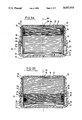
- FIGS. 2A and 2B are first and second side-sectional views of the container of FIG. 1, taken at right angles to each other and showing the container when empty and full, respectively;
- FIG. 3 is a partially cut-away illustration of the sleeve member as shown in FIGS. 2A and 2B;
- FIG. 4 is a side elevation of the integral piston head and anchor shown in FIGS. 2A and 2B;
- FIGS. 5A and 5B are respective plan view and side-sectional illustrations of the base shown in FIGS. 1, 2A and 2B;
- FIG. 6 is a cross-sectional view of the dispensing member shown in FIG. 1;
- FIG. 7 is a partially cut-away illustration of the adapter ring shown in FIGS. 1, 2A and 2B;
- FIGS. 8A and 8B are first and second side-sectional views of the container of FIG. 1, respectively corresponding to the views of FIGS. 2A and 2B, but showing a construction according to an alternative embodiment of the invention.
- FIG. 1 in which is shown a dispensing container, referenced generally 10, for viscous substances, such as cosmetic creams.
- container 10 is particularly characterized by its relatively simple design, and by its low production cost, the container having a small number of parts and typically being made from any suitably rigid plastic, such as polypropylene.
- the separate components of the container are preferably made by an injection molding technique.
- Container 10 comprises, typically, a cylindrical sleeve member 12 closed at an exposed end 14 by a dispensing member 16, inserted into sleeve member 12, as shown.
- Member 12 comprises typically a single aperture 18 through which the viscous substance stored in container 10 may be dispensed.
- Sleeve member 12 is rotatably retained in a base 20 by means of an adapter ring 22.
- FIGS. 2A to 7, illustrate the various components of container 10.
- Sleeve 12 (FIG. 3) defines a screw thread 24 which extends substantially along its entire height and is configured to receive a piston head 26 (FIG. 4), which has on an outer surface thereof a screw thread 28, configured to cooperate with screw thread 24.
- a viscous substance storage volume defined by an upper surface 25 of piston head 26, dispensing member 16 and an intervening portion of sleeve 12 is a viscous substance storage volume.
- piston head 26 and sleeve 12 causes relative axial motion of the piston head and the sleeve along a common axis of symmetry, referenced 30.
- sleeve 12 has hand grips 32 arranged along an upper edge thereof, so as to facilitate turning thereof.
- FIG. 2B shows piston head 26 in a position defining a maximum storage volume
- FIG. 2A shows piston head 26 adjacent to member 16, in a position defining a negligible storage volume.
- Sleeve 12 is constructed, as mentioned, so as to rotatably receive piston head 26.
- a ring 34 Connected to piston head 26 by means of flexible links 36 is a ring 34, preferably formed integrally therewith.
- Ring 34 has a diameter that is preferably larger than that of sleeve 12, such that when piston head 26 travels axially from a bottom end 38 of sleeve 12 to end 14 thereof, ring 34 is anchored in a fixed position adjacent to end 38 of sleeve 12.
- flexible links 36 are constructed such that their maximum extension corresponds to the height of sleeve 12. Accordingly, when piston head 26 is at the position shown in FIG. 2A, the links 36 are almost completely extended.
- relative axial motion between sleeve 12 and piston head 26 is achieved by causing relative axial rotation between the sleeve and the piston head. It is, therefore, necessary not only to anchor the piston head at end 38 of sleeve 12, as described, but also to prevent axial rotation of the piston head in order to prevent it rotating simultaneously with sleeve 12. According to the shown embodiment, this is achieved by mounting sleeve 12 in base 20 (FIGS. 2A, 2B, 5A and 5B), by means to be described.
- Base 20 includes a plurality of protrusions 42 formed on a surface 44 thereof and sleeve 12 is mounted in base 20 such that protrusions 41 defined on a bottom surface of ring 34 become locked with the protrusions 42 as piston head 26 is rotated together with sleeve 12. Once the piston head has become locked, as described, only sleeve 12 may be rotated, which causes the desired relative axial movement between the sleeve and the piston head.
- Sleeve 12 is rotatably mounted in base 20 by means of adapter ring 22 (FIG. 7).
- Adapter ring 22 is removably secured to base 20 by a first, typically annular projection 46 thereof which engages a second, typically annular projection 48 formed on an outer surface of the adapter ring.
- a projection 50, formed on sleeve 12 adjacent to end 14 thereof is engaged by an upper surface 52 of adapter ring 22, while annular projection 54 of ring 22 helps to retain sleeve 12 in the position shown in FIGS. 2A and 2B by means of annular projection 56 of sleeve 12.
- base 20 is shown, by way of example, to have a particular size relative to the sleeve 12 and the other components shown, the base may have any convenient size or configuration so long as the external dimensions and, if necessary, shape, of adapter ring 22 are in accordance therewith. This feature is of particular importance in the field of cosmetics, for example, wherein it may be wished to market different products in containers of different shapes and sizes.
- the viscous substance is dispensed by gripping base 20 and hand grip 32 and rotating each in an opposing direction. This induces the above-described relative rotation between sleeve 12 and piston head 26. As relative rotation is caused in a first predetermined direction, piston head 26 is driven axially along axis 30 towards member 16 thereby applying positive pressure to the viscous substance.
- the substance is dispensed through aperture 18 and may be removed from dispensing member 16 by, for example, a finger.
- dispensing of the substance in this manner is not only convenient and non-wasteful, but it also substantially reduces the chance of contaminating the substance by exposure to finger-borne and airborne germs.
- piston head 26 is driven axially along axis 30 away from member 16 thereby applying a negative pressure to the viscous substance so as to withdraw it into the container.
- FIGS. 8A and 8B there is shown a container 80, constructed and operative in accordance with an alternative embodiment of the invention.
- Container 80 is similar in construction and operation to container 10 (FIGS. 1 to 7) and similar components bear similar reference numerals and are not specifically described again in detail in conjunction with FIGS. 8A and 8B.
- Container 80 is characterized by the relatively small number of parts of which it is comprised.
- container 80 comprises a single integral member 82 having the same general configuration and function as members 12 and 16 of container 10.
- a single integral mounting member 84 having the same general configuration and function as base 20 and ring 22 of container 10.
- container 80 due to the very small number of parts of which container 80 is comprised, manufacture and assembly of the container is relatively inexpensive. Due to the integral nature of member 82, filling of container 80 with a preferred viscous substance is carried out through hole 18, by use of any suitable apparatus. This is in contrast to the easier filling of container 10 in which the container is filled and then dispensing member 16 is fitted.
Landscapes
- Containers And Packaging Bodies Having A Special Means To Remove Contents (AREA)
- Closures For Containers (AREA)
- Processes Of Treating Macromolecular Substances (AREA)
Applications Claiming Priority (1)
| Application Number | Priority Date | Filing Date | Title |
|---|---|---|---|
| IL87085A IL87085A (en) | 1988-07-12 | 1988-07-12 | Dispensing container for viscous substances |
Publications (1)
| Publication Number | Publication Date |
|---|---|
| US5037010A true US5037010A (en) | 1991-08-06 |
Family
ID=11059047
Family Applications (1)
| Application Number | Title | Priority Date | Filing Date |
|---|---|---|---|
| US07/378,270 Expired - Fee Related US5037010A (en) | 1988-07-12 | 1989-07-11 | Dispensing container for viscous substances |
Country Status (10)
| Country | Link |
|---|---|
| US (1) | US5037010A (de) |
| EP (1) | EP0350661B1 (de) |
| JP (1) | JP2549734B2 (de) |
| AT (1) | ATE121600T1 (de) |
| AU (1) | AU636844B2 (de) |
| CA (1) | CA1315244C (de) |
| DE (1) | DE68922346T2 (de) |
| IL (1) | IL87085A (de) |
| PT (1) | PT91120B (de) |
| ZA (1) | ZA894817B (de) |
Cited By (12)
| Publication number | Priority date | Publication date | Assignee | Title |
|---|---|---|---|---|
| US5454468A (en) * | 1994-03-11 | 1995-10-03 | United Microelectronics Corp. | Wafer container |
| US6655550B2 (en) * | 2001-07-19 | 2003-12-02 | Valois S.A.S. | Fluid product dispenser |
| US6655557B2 (en) * | 2000-09-22 | 2003-12-02 | L'oreal | Dispensing device and method |
| US20100140279A1 (en) * | 2007-08-17 | 2010-06-10 | Sea To Summit Pty., Ltd. | Collapsible Container |
| USD636238S1 (en) * | 2009-09-28 | 2011-04-19 | Kroger A/S | Caulking gun cylinder |
| US20120012592A1 (en) * | 2010-07-16 | 2012-01-19 | George David Lisch | Controlled base flash forming a standing ring |
| US20120074174A1 (en) * | 2010-08-25 | 2012-03-29 | Birgit Leisen Pollack | Container with Elevating Inner Wall |
| US20130068717A1 (en) * | 2011-09-16 | 2013-03-21 | Curtis Lee Hipkins | Scrunchable plastic disposable carbonated beverage bottle |
| WO2013176331A1 (ko) * | 2012-05-23 | 2013-11-28 | 주식회사 네스필러피케이지 | 회전 압출식 화장품 용기 |
| USD860787S1 (en) * | 2018-07-18 | 2019-09-24 | Gi Supply | Cap for tube container |
| US11612276B2 (en) * | 2021-08-17 | 2023-03-28 | Jorge Alberto Gimenez | Sanitizing apparatus |
| US12357074B2 (en) | 2022-04-26 | 2025-07-15 | Honestly Phresh, LLC | Personal care product applicator |
Families Citing this family (9)
| Publication number | Priority date | Publication date | Assignee | Title |
|---|---|---|---|---|
| FR2766678B1 (fr) * | 1997-08-04 | 2001-08-24 | Pierre Joulia | Perfectionnement pour mecanisme d'etuis tournant en deux pieces |
| GB9918453D0 (en) * | 1999-08-06 | 1999-10-06 | Eldred Stephen T | Dispenser for soft flowable materials |
| DE10222009A1 (de) * | 2002-05-17 | 2003-12-04 | Henkel Kgaa | Vorrichtung zur Aufnahme einer in das Innere eines Toilettenbeckens oder dergl. abzugebenden gelförmigen Wirkstoffzubereitung |
| KR101101777B1 (ko) * | 2009-04-27 | 2012-01-05 | (주)레이덱스 | 분리형 내용물 접시와 이를 이용한 멀티 색상을 갖는 고형 파운데이션 제품의 표면에 무늬를 부각시키는 화장품 성형방법 |
| GB2472412A (en) | 2009-08-05 | 2011-02-09 | Twistub Ltd | Dispenser for viscous fluid |
| US8794293B2 (en) * | 2010-08-10 | 2014-08-05 | S.C. Johnson & Son, Inc. | Single dose applicator and method |
| KR101486198B1 (ko) * | 2014-10-14 | 2015-02-11 | 김진우 | 회전 압출식 화장품 용기 |
| TR201616010A2 (tr) * | 2015-11-26 | 2017-01-23 | Zeki Plastik Plastik Ambalaj Kalip Sanayi Ve Ticaret Ltd Sirketi | Deği̇şti̇ri̇lebi̇li̇r sivi veya plazma haznesi̇ni̇n hareketli̇ di̇şli̇ si̇stemi̇ i̇le boşaltmaya uygun bi̇r ambalaj |
| EP4133968B1 (de) * | 2021-08-11 | 2023-11-01 | Chanel Parfums Beauté | Schutzsystem für eine dose, die ein kosmetikprodukt enthält |
Citations (32)
| Publication number | Priority date | Publication date | Assignee | Title |
|---|---|---|---|---|
| US1025512A (en) * | 1910-10-14 | 1912-05-07 | Craven Engineering Company | Receptacle for containing and discharging semisolid and pasty substances. |
| US1055028A (en) * | 1911-12-16 | 1913-03-04 | Edward C Flynn | Paste-cup. |
| GB248596A (en) * | 1925-05-14 | 1926-03-11 | Reginald William Penn | Improvements in or relating to air-tight receptacles with removable covers |
| US1642108A (en) * | 1926-06-29 | 1927-09-13 | Walter Rutherford | Dispensing container |
| US1651687A (en) * | 1926-12-11 | 1927-12-06 | Charles W Fislar | Dispensing device |
| US1772887A (en) * | 1928-01-19 | 1930-08-12 | Couet Augustin Emmanuel Jan De | Container for semiliquid materials |
| DE531026C (de) * | 1929-12-11 | 1931-08-06 | Edmund Weidner Dr | Abgabevorrichtung fuer Reinigungspasten, Cremes o. dgl. pastenfoermige Massen |
| GB401003A (en) * | 1932-05-07 | 1933-11-06 | Ottomar Voelk | Improvements in boxes particularly for viscous substances |
| US1936822A (en) * | 1932-05-07 | 1933-11-28 | Boenecke Alfred | Box, especially for viscous substances |
| GB468029A (en) * | 1936-12-31 | 1937-06-28 | Frank Roy Goshawk | Improvements in containers for creams and semi-solid substances |
| GB514844A (en) * | 1938-05-17 | 1939-11-20 | Joseph Van Praagh | An improved device or container for the use of substances in the form of liquids, emulsions, creams, pastes, powders, and solids |
| US2335049A (en) * | 1942-08-29 | 1943-11-23 | Finkelstein Louis | Dispensing device for paste, cream, etc. |
| GB650054A (en) * | 1944-02-15 | 1951-02-14 | Josef Gabler | Improvements in or relating to paste dispensing devices |
| US2568856A (en) * | 1950-02-07 | 1951-09-25 | Albert E Hartmann | Soap containing handle |
| US2599379A (en) * | 1948-02-24 | 1952-06-03 | Gabler Josef | Screw actuated dispensing mechanism and refill unit therefor |
| US2605936A (en) * | 1948-02-25 | 1952-08-05 | Gabler Josef | Dispenser of pasty substances from replaceable inner containers having threaded followers |
| US2626730A (en) * | 1944-02-15 | 1953-01-27 | Gabler Josef | Container for pasty substances |
| US2627365A (en) * | 1948-02-25 | 1953-02-03 | Gabler Josef | Cream box |
| US2635789A (en) * | 1948-02-24 | 1953-04-21 | Gabler Josef | Dispensing device |
| US2656953A (en) * | 1951-06-25 | 1953-10-27 | John W Rich | Dispensing device |
| GB755224A (en) * | 1954-01-04 | 1956-08-22 | Charles Samuel Garland | Improvements in or relating to containers for liquid adhesives |
| US2818973A (en) * | 1955-06-03 | 1958-01-07 | Coty Inc | Cosmetic containers |
| US3059820A (en) * | 1960-07-12 | 1962-10-23 | Gabler Josef | Box for holding and delivering pasty substances |
| US3128923A (en) * | 1962-03-06 | 1964-04-14 | Gabler Josef | Container for receiving and delivering pasty substances |
| GB963207A (en) * | 1961-09-01 | 1964-07-08 | Charles Douglas Waller | Improvements in or relating to dispensers |
| FR1377658A (fr) * | 1963-11-22 | 1964-11-06 | Boîte avec récipient intérieur et couvercle pour la réception et la distributionde matières pâteuses ou en forme de bâtons | |
| US3241729A (en) * | 1964-11-16 | 1966-03-22 | Gabler Josef | Dispensers for cosmetic and medicinal preparations |
| GB1035945A (en) * | 1963-03-15 | 1966-07-13 | George Basil Kolokythas | Closure for container |
| GB1307700A (en) * | 1969-11-20 | 1973-02-21 | Sterling Drug Inc | Overcap for an aerosol spray dispenser |
| US4022205A (en) * | 1973-11-05 | 1977-05-10 | Tenczar Francis J | Fluid connectors |
| US4139127A (en) * | 1976-12-16 | 1979-02-13 | Orange Products, Inc. | Plunger-type dispenser with ratchet actuator |
| WO1983003572A1 (en) * | 1982-04-06 | 1983-10-27 | Baxter Travenol Lab | Antibacterial seal |
Family Cites Families (1)
| Publication number | Priority date | Publication date | Assignee | Title |
|---|---|---|---|---|
| US2818073A (en) | 1955-03-21 | 1957-12-31 | Richard G Taylor | Tobacco smoke filtering material |
-
1988
- 1988-07-12 IL IL87085A patent/IL87085A/xx not_active IP Right Cessation
-
1989
- 1989-06-19 AT AT89111136T patent/ATE121600T1/de not_active IP Right Cessation
- 1989-06-19 DE DE68922346T patent/DE68922346T2/de not_active Expired - Fee Related
- 1989-06-19 EP EP89111136A patent/EP0350661B1/de not_active Expired - Lifetime
- 1989-06-23 AU AU37007/89A patent/AU636844B2/en not_active Ceased
- 1989-06-26 ZA ZA894817A patent/ZA894817B/xx unknown
- 1989-07-04 CA CA000604725A patent/CA1315244C/en not_active Expired - Fee Related
- 1989-07-05 JP JP1173894A patent/JP2549734B2/ja not_active Expired - Fee Related
- 1989-07-11 US US07/378,270 patent/US5037010A/en not_active Expired - Fee Related
- 1989-07-11 PT PT91120A patent/PT91120B/pt not_active IP Right Cessation
Patent Citations (32)
| Publication number | Priority date | Publication date | Assignee | Title |
|---|---|---|---|---|
| US1025512A (en) * | 1910-10-14 | 1912-05-07 | Craven Engineering Company | Receptacle for containing and discharging semisolid and pasty substances. |
| US1055028A (en) * | 1911-12-16 | 1913-03-04 | Edward C Flynn | Paste-cup. |
| GB248596A (en) * | 1925-05-14 | 1926-03-11 | Reginald William Penn | Improvements in or relating to air-tight receptacles with removable covers |
| US1642108A (en) * | 1926-06-29 | 1927-09-13 | Walter Rutherford | Dispensing container |
| US1651687A (en) * | 1926-12-11 | 1927-12-06 | Charles W Fislar | Dispensing device |
| US1772887A (en) * | 1928-01-19 | 1930-08-12 | Couet Augustin Emmanuel Jan De | Container for semiliquid materials |
| DE531026C (de) * | 1929-12-11 | 1931-08-06 | Edmund Weidner Dr | Abgabevorrichtung fuer Reinigungspasten, Cremes o. dgl. pastenfoermige Massen |
| GB401003A (en) * | 1932-05-07 | 1933-11-06 | Ottomar Voelk | Improvements in boxes particularly for viscous substances |
| US1936822A (en) * | 1932-05-07 | 1933-11-28 | Boenecke Alfred | Box, especially for viscous substances |
| GB468029A (en) * | 1936-12-31 | 1937-06-28 | Frank Roy Goshawk | Improvements in containers for creams and semi-solid substances |
| GB514844A (en) * | 1938-05-17 | 1939-11-20 | Joseph Van Praagh | An improved device or container for the use of substances in the form of liquids, emulsions, creams, pastes, powders, and solids |
| US2335049A (en) * | 1942-08-29 | 1943-11-23 | Finkelstein Louis | Dispensing device for paste, cream, etc. |
| US2626730A (en) * | 1944-02-15 | 1953-01-27 | Gabler Josef | Container for pasty substances |
| GB650054A (en) * | 1944-02-15 | 1951-02-14 | Josef Gabler | Improvements in or relating to paste dispensing devices |
| US2599379A (en) * | 1948-02-24 | 1952-06-03 | Gabler Josef | Screw actuated dispensing mechanism and refill unit therefor |
| US2635789A (en) * | 1948-02-24 | 1953-04-21 | Gabler Josef | Dispensing device |
| US2605936A (en) * | 1948-02-25 | 1952-08-05 | Gabler Josef | Dispenser of pasty substances from replaceable inner containers having threaded followers |
| US2627365A (en) * | 1948-02-25 | 1953-02-03 | Gabler Josef | Cream box |
| US2568856A (en) * | 1950-02-07 | 1951-09-25 | Albert E Hartmann | Soap containing handle |
| US2656953A (en) * | 1951-06-25 | 1953-10-27 | John W Rich | Dispensing device |
| GB755224A (en) * | 1954-01-04 | 1956-08-22 | Charles Samuel Garland | Improvements in or relating to containers for liquid adhesives |
| US2818973A (en) * | 1955-06-03 | 1958-01-07 | Coty Inc | Cosmetic containers |
| US3059820A (en) * | 1960-07-12 | 1962-10-23 | Gabler Josef | Box for holding and delivering pasty substances |
| GB963207A (en) * | 1961-09-01 | 1964-07-08 | Charles Douglas Waller | Improvements in or relating to dispensers |
| US3128923A (en) * | 1962-03-06 | 1964-04-14 | Gabler Josef | Container for receiving and delivering pasty substances |
| GB1035945A (en) * | 1963-03-15 | 1966-07-13 | George Basil Kolokythas | Closure for container |
| FR1377658A (fr) * | 1963-11-22 | 1964-11-06 | Boîte avec récipient intérieur et couvercle pour la réception et la distributionde matières pâteuses ou en forme de bâtons | |
| US3241729A (en) * | 1964-11-16 | 1966-03-22 | Gabler Josef | Dispensers for cosmetic and medicinal preparations |
| GB1307700A (en) * | 1969-11-20 | 1973-02-21 | Sterling Drug Inc | Overcap for an aerosol spray dispenser |
| US4022205A (en) * | 1973-11-05 | 1977-05-10 | Tenczar Francis J | Fluid connectors |
| US4139127A (en) * | 1976-12-16 | 1979-02-13 | Orange Products, Inc. | Plunger-type dispenser with ratchet actuator |
| WO1983003572A1 (en) * | 1982-04-06 | 1983-10-27 | Baxter Travenol Lab | Antibacterial seal |
Cited By (14)
| Publication number | Priority date | Publication date | Assignee | Title |
|---|---|---|---|---|
| US5454468A (en) * | 1994-03-11 | 1995-10-03 | United Microelectronics Corp. | Wafer container |
| US6655557B2 (en) * | 2000-09-22 | 2003-12-02 | L'oreal | Dispensing device and method |
| US6655550B2 (en) * | 2001-07-19 | 2003-12-02 | Valois S.A.S. | Fluid product dispenser |
| US20100140279A1 (en) * | 2007-08-17 | 2010-06-10 | Sea To Summit Pty., Ltd. | Collapsible Container |
| USD636238S1 (en) * | 2009-09-28 | 2011-04-19 | Kroger A/S | Caulking gun cylinder |
| US9254604B2 (en) | 2010-07-16 | 2016-02-09 | Amcor Limited | Controlled base flash forming a standing ring |
| US20120012592A1 (en) * | 2010-07-16 | 2012-01-19 | George David Lisch | Controlled base flash forming a standing ring |
| US20120074174A1 (en) * | 2010-08-25 | 2012-03-29 | Birgit Leisen Pollack | Container with Elevating Inner Wall |
| US8627987B2 (en) * | 2010-08-25 | 2014-01-14 | Wisys Technology Foundation | Container with elevating inner wall |
| US20130068717A1 (en) * | 2011-09-16 | 2013-03-21 | Curtis Lee Hipkins | Scrunchable plastic disposable carbonated beverage bottle |
| WO2013176331A1 (ko) * | 2012-05-23 | 2013-11-28 | 주식회사 네스필러피케이지 | 회전 압출식 화장품 용기 |
| USD860787S1 (en) * | 2018-07-18 | 2019-09-24 | Gi Supply | Cap for tube container |
| US11612276B2 (en) * | 2021-08-17 | 2023-03-28 | Jorge Alberto Gimenez | Sanitizing apparatus |
| US12357074B2 (en) | 2022-04-26 | 2025-07-15 | Honestly Phresh, LLC | Personal care product applicator |
Also Published As
| Publication number | Publication date |
|---|---|
| JP2549734B2 (ja) | 1996-10-30 |
| JPH02233384A (ja) | 1990-09-14 |
| IL87085A0 (en) | 1988-12-30 |
| EP0350661A2 (de) | 1990-01-17 |
| DE68922346D1 (de) | 1995-06-01 |
| DE68922346T2 (de) | 1995-10-12 |
| EP0350661B1 (de) | 1995-04-26 |
| IL87085A (en) | 1992-07-15 |
| EP0350661A3 (en) | 1990-12-27 |
| PT91120B (pt) | 1994-09-30 |
| ZA894817B (en) | 1990-04-25 |
| AU636844B2 (en) | 1993-05-13 |
| CA1315244C (en) | 1993-03-30 |
| AU3700789A (en) | 1990-01-18 |
| ATE121600T1 (de) | 1995-05-15 |
| PT91120A (pt) | 1990-02-08 |
Similar Documents
| Publication | Publication Date | Title |
|---|---|---|
| US5037010A (en) | Dispensing container for viscous substances | |
| US3155281A (en) | Container | |
| JPH10502545A (ja) | 化粧品用容器 | |
| US10858170B2 (en) | Dual dispensing cosmetic container | |
| US4219283A (en) | Container having an interiorly telescoping dispensing member | |
| US4974981A (en) | Cosmetic powder brush with metered powder dispenser | |
| US2816309A (en) | Combined container and applicator | |
| JPH05270577A (ja) | 適量分与装置 | |
| US4917520A (en) | Applicator brush | |
| US6174099B1 (en) | Device for applying liquid cosmetic products | |
| IE53601B1 (en) | Roll-on dispensing device | |
| US5944434A (en) | Applicator package | |
| EP0353043A2 (de) | Klebstoffspender | |
| US5234132A (en) | Actuator for dispensing pump | |
| US5913631A (en) | Cosmetic applicator | |
| US3612704A (en) | Container-dispenser for material in stick form | |
| US5346323A (en) | Push-up package | |
| GB1571662A (en) | Liquid applicator | |
| GB2304825A (en) | Dispenser for edible food spreads | |
| US20230032917A1 (en) | Metered dose topical applicator | |
| JPS6132700Y2 (de) | ||
| JPH0627578Y2 (ja) | 混合する物質を収容する容器用キャップ | |
| KR930005398Y1 (ko) | 화장용 크림의 배출장치 | |
| JP7749514B2 (ja) | 繰り出し容器 | |
| JP2528702Y2 (ja) | 棒状化粧品繰出し容器 |
Legal Events
| Date | Code | Title | Description |
|---|---|---|---|
| AS | Assignment |
Owner name: LAGEEN BOX & CAN FACTORY LTD., ISRAEL Free format text: ASSIGNMENT OF ASSIGNORS INTEREST.;ASSIGNOR:DIKSTEIN, SHABTAI;REEL/FRAME:005121/0793 Effective date: 19890620 Owner name: RESDEVCO RESEARCH & DEVELOPMENT CO. LTD., ISRAEL Free format text: ASSIGNMENT OF ASSIGNORS INTEREST.;ASSIGNOR:DIKSTEIN, SHABTAI;REEL/FRAME:005121/0793 Effective date: 19890620 |
|
| FPAY | Fee payment |
Year of fee payment: 4 |
|
| AS | Assignment |
Owner name: GENERAL ELECTRIC CAPITAL CORPORATION, AS AGENT, IL Free format text: SECURITY INTEREST;ASSIGNOR:W. BRAUN COMPANY;REEL/FRAME:009342/0103 Effective date: 19980626 |
|
| AS | Assignment |
Owner name: W. BRAUN COMPANY, L.L.C., MISSOURI Free format text: MERGER;ASSIGNOR:W. BRAUN COMPANY, A CORP. OF DE;REEL/FRAME:009678/0739 Effective date: 19981230 |
|
| AS | Assignment |
Owner name: KRANSON INDUSTRIES, INC., A CORP. OF MISSOURI, MIS Free format text: ASSIGNMENT OF ASSIGNORS INTEREST;ASSIGNOR:W. BRAUM COMPANY, L.L.C., A DELAWARE LIMITED LIABILITY COMPANY;REEL/FRAME:009689/0478 Effective date: 19981230 |
|
| AS | Assignment |
Owner name: GENERAL ELECTRIC CAPITAL CORPORATION, AS AGENT, IL Free format text: AMENDMENT NO. 2 TO PATENT SECURITY AGREEMENT;ASSIGNOR:KRANSON INDUSTRIES, INC.;REEL/FRAME:009711/0119 Effective date: 19981230 |
|
| FPAY | Fee payment |
Year of fee payment: 8 |
|
| AS | Assignment |
Owner name: W. BRAUN COMPANY, MISSOURI Free format text: TERMINATION OF SECURITY INTERST;ASSIGNOR:GENERAL ELECTRIC CAPITAL CORPORATION;REEL/FRAME:010321/0653 Effective date: 19991101 Owner name: KRANSON INDUSTRIES, INC., MISSOURI Free format text: TERMINATION OF SECURITY INTEREST;ASSIGNOR:GENERAL ELECTRIC CAPITAL CORPORATION;REEL/FRAME:010321/0781 Effective date: 19991101 |
|
| AS | Assignment |
Owner name: LATHAM & WATKINS, ILLINOIS Free format text: SECURITY INTEREST;ASSIGNOR:KRANSON INDUSTRIES, INC.;REEL/FRAME:010567/0281 Effective date: 19991029 |
|
| REMI | Maintenance fee reminder mailed | ||
| LAPS | Lapse for failure to pay maintenance fees | ||
| STCH | Information on status: patent discontinuation |
Free format text: PATENT EXPIRED DUE TO NONPAYMENT OF MAINTENANCE FEES UNDER 37 CFR 1.362 |
|
| FP | Lapsed due to failure to pay maintenance fee |
Effective date: 20030806 |
|
| AS | Assignment |
Owner name: ANTARES CAPITAL CORPORATION, AS AGENT, ILLINOIS Free format text: CORRECTIVE ASSIGNMENT TO CORRECT THE RECEIVING PARTY INFORMATION- SHOULD READ ANTARES CAPITAL CORPORATION, AS AGENT PREVIOUSLY RECORDED ON REEL 010567 FRAME 0281;ASSIGNOR:KRANSON INDUSTRIES, INC.;REEL/FRAME:017996/0688 Effective date: 19991029 |
|
| AS | Assignment |
Owner name: KRANSON INDUSTRIES, INC., MISSOURI Free format text: RELEASE BY SECURED PARTY;ASSIGNOR:ANTARES CAPITAL CORPORATION, AS AGENT;REEL/FRAME:018039/0310 Effective date: 20060726 |
|
| AS | Assignment |
Owner name: KRANSON INDUSTRIES, INC., MISSOURI Free format text: RELEASE BY SECURED PARTY;ASSIGNOR:ANTARES CAPITAL CORPORATION, AS AGENT;REEL/FRAME:018746/0570 Effective date: 20060726 |