US5042888A - Anchor bolt having a spring - Google Patents
Anchor bolt having a spring Download PDFInfo
- Publication number
- US5042888A US5042888A US07/553,736 US55373690A US5042888A US 5042888 A US5042888 A US 5042888A US 55373690 A US55373690 A US 55373690A US 5042888 A US5042888 A US 5042888A
- Authority
- US
- United States
- Prior art keywords
- expansion
- sleeve
- threaded rod
- spring member
- fastening sleeve
- Prior art date
- Legal status (The legal status is an assumption and is not a legal conclusion. Google has not performed a legal analysis and makes no representation as to the accuracy of the status listed.)
- Expired - Fee Related
Links
Images


Classifications
-
- F—MECHANICAL ENGINEERING; LIGHTING; HEATING; WEAPONS; BLASTING
- F16—ENGINEERING ELEMENTS AND UNITS; GENERAL MEASURES FOR PRODUCING AND MAINTAINING EFFECTIVE FUNCTIONING OF MACHINES OR INSTALLATIONS; THERMAL INSULATION IN GENERAL
- F16B—DEVICES FOR FASTENING OR SECURING CONSTRUCTIONAL ELEMENTS OR MACHINE PARTS TOGETHER, e.g. NAILS, BOLTS, CIRCLIPS, CLAMPS, CLIPS OR WEDGES; JOINTS OR JOINTING
- F16B13/00—Dowels or other devices fastened in walls or the like by inserting them in holes made therein for that purpose
- F16B13/04—Dowels or other devices fastened in walls or the like by inserting them in holes made therein for that purpose with parts gripping in the hole or behind the reverse side of the wall after inserting from the front
- F16B13/06—Dowels or other devices fastened in walls or the like by inserting them in holes made therein for that purpose with parts gripping in the hole or behind the reverse side of the wall after inserting from the front combined with expanding sleeve
- F16B13/063—Dowels or other devices fastened in walls or the like by inserting them in holes made therein for that purpose with parts gripping in the hole or behind the reverse side of the wall after inserting from the front combined with expanding sleeve by the use of an expander
- F16B13/065—Dowels or other devices fastened in walls or the like by inserting them in holes made therein for that purpose with parts gripping in the hole or behind the reverse side of the wall after inserting from the front combined with expanding sleeve by the use of an expander fastened by extracting the screw, nail or the like
-
- F—MECHANICAL ENGINEERING; LIGHTING; HEATING; WEAPONS; BLASTING
- F16—ENGINEERING ELEMENTS AND UNITS; GENERAL MEASURES FOR PRODUCING AND MAINTAINING EFFECTIVE FUNCTIONING OF MACHINES OR INSTALLATIONS; THERMAL INSULATION IN GENERAL
- F16B—DEVICES FOR FASTENING OR SECURING CONSTRUCTIONAL ELEMENTS OR MACHINE PARTS TOGETHER, e.g. NAILS, BOLTS, CIRCLIPS, CLAMPS, CLIPS OR WEDGES; JOINTS OR JOINTING
- F16B13/00—Dowels or other devices fastened in walls or the like by inserting them in holes made therein for that purpose
- F16B13/04—Dowels or other devices fastened in walls or the like by inserting them in holes made therein for that purpose with parts gripping in the hole or behind the reverse side of the wall after inserting from the front
- F16B13/08—Dowels or other devices fastened in walls or the like by inserting them in holes made therein for that purpose with parts gripping in the hole or behind the reverse side of the wall after inserting from the front with separate or non-separate gripping parts moved into their final position in relation to the body of the device without further manual operation
- F16B13/0858—Dowels or other devices fastened in walls or the like by inserting them in holes made therein for that purpose with parts gripping in the hole or behind the reverse side of the wall after inserting from the front with separate or non-separate gripping parts moved into their final position in relation to the body of the device without further manual operation with an expansible sleeve or dowel body driven against a tapered or spherical expander plug
Definitions
- the invention relates to an anchor bolt having a spring, with spring being used to fix various mechanical parts, pipings or the like on a concrete structure such as wall, ceiling, floor or the like.
- An anchor bolt of the type mentioned above most widely a threaded rod, an expansion body formed at one end of the threaded rod as an anchor body, and an expansion sleeve fitted on the threaded rod penetrating therethrough wherein the expansion sleeve is expanded by the expansion body so as to hold the anchor bolt in a hole of, for example, concrete structure above.
- the known anchor bolt is advantageous due to its simple structure and is easy to handle in construction work a violent vibration or an earthquake is likely to cause some problems to the anchor bolt. More particularly, the vibration or earthquake causes some cracks on the wall defining the hole, thereby removing the anchor bolt from the hole or gradually moving the bolt outwardly.
- some other anchor bolts for example, disclosed in Japanese Tokkai Publication No. 63-285310 or in U.S. Pat. No.
- 4,613,264 which comprise a spring member employed to solve the problem mentioned above, with the spring member being interposed between the expansion body and a stopper formed on the threaded rod of anchor body so that a force outwardly pulling the threaded rod acts on the expansion body by the spring member and expands the expansion sleeve.
- an object of the invention is to provide an anchor bolt comprising a threaded rod which is substantially of the same size and shape as that included in the conventional anchor bolts, wherein the expansion of the sleeve is nevertheless surely effected securing the threaded rod in the hole of concrete structure, without a fear of removal or loosening of the rod even in a case where the cracks are likely to be produced around the hole due to the violent vibrations or an earthquake.
- an anchor bolt having a spring member comprises a fastening sleeve, with an expansion sleeve and an expansion body, the expansion body being disposed at one end portion of a threaded rod as an anchor main body.
- the expansion sleeve is fitted on the threaded rod, with the fastening sleeve and the spring member being loosely fitted on the threaded rod wherein the fastening sleeve fixed within an inlet portion of a hole drilled in a concrete body compresses the spring member so as to urge the expansion sleeve to be expanded by the expansion body which is inserted deep in the hole of the concrete structure together with the threaded rod.
- the expansion body disposed at the end portion of the threaded rod may either be formed integral with the threaded rod, or be formed as a nut mating therewith.
- the threaded rod is inserted into the hole with its expansion body leading the other parts.
- the fastening sleeve is then forced into the inlet portion of the hole so as to be fixed therein.
- the spring member which is thus compressed by the fastening sleeve will expand the expansion sleeve, thereby securing the threaded rod in the hole.
- the spring member always strongly urges the expansion sleeve toward the expansion body so that this sleeve is displaced from its original position to a new position nearer the expansion body if the vibration or cracks would unexpectedly and undesirably cause disengagement of the surface of the expansion sleeve from the inner wall surface of the hole.
- Such a displacement of the expansion sleeve results in additional expansion thereof which restore the rigid and enforced engagement of the sleeve with the wall surface.
- the end portion of the spring member is exposed to the outside through the opening of the fastening sleeve which is compelled to fit the inlet portion of the hole.
- the anchor bolt of the invention is advantageous in that the expansion sleeve can be sufficiently expanded by the spring member merely by the striking of the fastening sleeve into the hole in the concrete structure.
- the threaded rod functioning as the anchor main body is thus firmly fixed in the hole in such a stable state that any possible cracks on the inner wall which would take place around the hole due to the strong vibrations or an earthquake cannot cause the removal or loosening of the threaded rod.
- the anchor bolt in the invention can be manufactured at a lower cost because it is simple in its structure comprising a smaller number of parts, particularly because the length and shape of the threaded rod itself are not substantially different from those of the known usual anchor bolt.
- Visual inspection of the spring member favorably makes it possible to check for the presence thereof during construction work because the end of the spring member is exposed to the outside through the opening of the fastening sleeve.
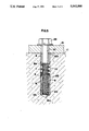
- FIG. 1 is a front elevation of an anchor bolt having a spring member in an embodiment of the invention
- FIG. 2 and 3 are front elevations showing partially in cross section the anchor bolt which is being installed or used;
- FIG. 4 is a front elevation of a further anchor bolt having a spring member in another embodiment of the invention.
- FIG. 5 is a front elevation showing partially in cross section the further anchor bolt which is being used.
- an anchor bolt having a spring member comprises a threaded rod 1 as an anchor main body.
- the threaded rod comprises an expansion body 2 formed integral with one end portion of the threaded rod, with the expansion body 2 being of a frustum shape and having a tapered surface 2a gradually increasing outwardly the diameter of the expansion body.
- the threaded rod 1 further comprises at its other end portion a male threaded 3 adapted to be threaded to a fastening nut 4.
- the shape of the threaded rod it is similar to those which are included in the known anchor bolts of this type.
- An expansion sleeve 5, fitted loosely on the threaded rod 1, is manufactured either by cutting into a predetermined length of a thin walled metal pipe, or formed by the powder metallurgy into a cylindrical shape of thin wall.
- a tapered surface 5a Formed at an inner surface of an expansible part near one extremity 5b of the expansion sleeve 5 is a tapered surface 5a which extends along the tapered surface 2a of the expansion body 2.
- a plurality of slits 6 are formed to extend in axial direction from the extremity 5b of the expansion sleeve 5 whereby it can readily be expanded solely by a resilient force exerted by a spring member 7 which will be described below.
- the spring member 7 urges the expansion sleeve 5 toward the expansion body, and the spring member is preferably a coiled spring made by coiling a spring steel wire into a helical shape of substantially the same outer diameter as the expansion sleeve 5.
- the spring member 7 is loosely mounted in its uncompressed state on the screw rod 1, with its leading end bearing against the other extremity of the expansion sleeve 5.
- a cylindrical a fastening sleeve 8, made of a metal, has an outer diameter slightly greater than that of the expansion sleeve 5.
- the fastening sleeve 8 has an inner diameter also slightly greater than the outer diameter of the male threaded 3.
- a tapered portion 8a is formed near a tip end of the fastening sleeve 8 in such a manner as gradually decreasing the outer diameter toward said tip end.
- a portion extending in axial direction of the fastening sleeve 8 is cut off to form an opening 9 which extends between the tip end and a trailing end of the fastening sleeve 8.
- the fastening sleeve 8 is loosely fitted on the threaded rod 1, following the spring member (i.e., coiled spring ) 7 which is previously set around the rod 1.
- a trailing straight end portion 7a extending from and in axial direction of the spring member (i.e., coiled spring ) 7 is exposed to the outside through the opening 9 after the fastening sleeve 8 is mounted on said rod 1.
- the nut 4 is removed from the threaded rod 1 before insertion in a hole 12 drilled in a concrete structure 11, with its expansion body 2 leading the other parts of the anchor bolt. After a leading thick end of the expansion body 2 has reached a bottom 12a of the hole so as to be supported thereon, a cylindrical pressing tool 15 is fitted on the end of the threaded rod 1 such that the tool 15 comes into pressing contact with the trailing end 8b of the fastening sleeve 8.
- the pressing tool 15 is struck to forcibly insert the fastening sleeve 8 into the hole 12 and to secure it in an inlet portion 12b thereof whereby the fastening sleeve 8 compresses the spring member (i.e., coiled spring) 7.
- the compressed spring member 7 urges the expansion sleeve 5 toward the expansion body 2 so that the sleeve 5 is expanded diametrically due to the tapered surface 2a of the expansion body 2 to such a degree that the expansion sleeve 5 engages with a wall surface 12c around the hole 12, thus fixing the threaded rod 1 within the hole 12.
- the trailing straight portion 7a of the spring member 7 extends through the opening 9 of the fastening sleeve 8 and is exposed to the outside, allowing visual inspection of the presence or absence of said spring member 7.
- the nut 4 is threaded on the male thread 3 of the threaded rod 1 fastened to the concrete structure 11 in order to secure thereon an object 13 to be mounted. It is to be noted that the thus threaded nut 4 exerts a force pulling the threaded rod 1 thereto to further ensure the expansion of the expansion sleeve 5.
- the spring member 7 always urges the expansion sleeve 5 of the anchor bolt which is securedly set in the hole 12 toward the expansion body 2.
- the expansion sleeve 5 automatically moves toward the expansion body 2 in the event of the violent vibrations or an earthquake which might cause the cracks on the wall 12c around the hole 12 and, consequently any disengagement of the expansion sleeve 5 from the wall 12c. Such a spontaneous displacement further expands the expansion sleeve 5 to reengage with the wall 12c, thereby keeping the threaded rod 1 retained firmly within the hole.
- the expansion body 2 is formed as a nut 20 through which is threaded is a male thread 23 of a bolt 21 having a head 22.
- the bolt 21 is first removed as shown in FIG. 4, and then the nut 20, the expansion sleeve 5, the spring member 7 and the fastening sleeve 8 are inserted in the hole 12 in this order.
- the pressing tool 25, comprising a guiding protrusion 26, is used to strike the fastening sleeve 8 into the inlet portion 12b of said hole 12.
- the fastening sleeve 8 compresses the spring member 7 to forcibly expand the expansion sleeve 5.
- expansion body 2 is shaped as a nut 20 in the further embodiment, it is possible to employ the bolt 21 shown in FIG. 5 in place of the threaded rod 1 in order to fasten the object 13 to the concrete structure 11.
Landscapes
- Engineering & Computer Science (AREA)
- General Engineering & Computer Science (AREA)
- Mechanical Engineering (AREA)
- Dowels (AREA)
- Joining Of Building Structures In Genera (AREA)
Applications Claiming Priority (2)
| Application Number | Priority Date | Filing Date | Title |
|---|---|---|---|
| JP2149481A JPH0446211A (ja) | 1990-06-06 | 1990-06-06 | ばね付きアンカーボルト |
| JP2-149481 | 1990-06-06 |
Publications (1)
| Publication Number | Publication Date |
|---|---|
| US5042888A true US5042888A (en) | 1991-08-27 |
Family
ID=15476096
Family Applications (1)
| Application Number | Title | Priority Date | Filing Date |
|---|---|---|---|
| US07/553,736 Expired - Fee Related US5042888A (en) | 1990-06-06 | 1990-07-18 | Anchor bolt having a spring |
Country Status (5)
| Country | Link |
|---|---|
| US (1) | US5042888A (de) |
| EP (1) | EP0461790B1 (de) |
| JP (1) | JPH0446211A (de) |
| AT (1) | ATE100906T1 (de) |
| DE (1) | DE69101085T2 (de) |
Cited By (37)
| Publication number | Priority date | Publication date | Assignee | Title |
|---|---|---|---|---|
| EP0538128A1 (de) * | 1991-10-16 | 1993-04-21 | Jeumont Industrie - Ji | Mittel zum Verankern von einem Teil bezüglich eines anderen Teils |
| US5261203A (en) * | 1991-05-22 | 1993-11-16 | Suk Kyu Yoon | Movable barrier capable of disassembly |
| NL1002635C2 (nl) * | 1996-03-18 | 1997-09-22 | Bihca Precision B V | Spanbout. |
| US5730540A (en) * | 1996-09-03 | 1998-03-24 | Lockheed Martin Corporation | Hole filling receptacle assembly |
| US6068226A (en) * | 1997-01-28 | 2000-05-30 | Anders; Glen | Detachable anchor |
| US6109578A (en) * | 1998-08-10 | 2000-08-29 | Guthrie; Karl | Borehole-engaging apparatus |
| US6283426B1 (en) | 2000-02-04 | 2001-09-04 | Karl Guthrie | Spring-loaded camming nut |
| US20030219308A1 (en) * | 2002-05-24 | 2003-11-27 | Boulais Keith E. | Barrier system |
| US6729821B2 (en) | 2002-02-28 | 2004-05-04 | Karl Guthrie | Expansion bolt |
| US20040164563A1 (en) * | 2002-04-09 | 2004-08-26 | Kitzis Roger S. | Anti-animal container lock |
| US20040175251A1 (en) * | 2003-03-07 | 2004-09-09 | Paul Sigismund D. | Concrete anchor |
| US20040213633A1 (en) * | 2002-02-28 | 2004-10-28 | Karl Guthrie | Expansion bolt |
| WO2005111438A1 (en) * | 2004-05-19 | 2005-11-24 | Vibrosystm Inc. | Shear component breakage detection |
| US20060022101A1 (en) * | 2004-07-27 | 2006-02-02 | Reeves Eric W | Expansible hole anchor with enlarged chock-releasing striker head |
| US20060231709A1 (en) * | 2003-12-30 | 2006-10-19 | Karl Guthrie | Expansion bolt |
| US20080073821A1 (en) * | 2006-09-26 | 2008-03-27 | Denso Corporation | Holding device for holding object |
| US20080282640A1 (en) * | 2007-05-16 | 2008-11-20 | Mathews Thomas F | Cable anchor |
| US20090056267A1 (en) * | 2007-07-12 | 2009-03-05 | Reeves Eric William | Expansible hole anchor |
| CN102182737A (zh) * | 2011-06-10 | 2011-09-14 | 温少松 | 隐形紧压拉爆螺丝 |
| CN102927100A (zh) * | 2012-10-30 | 2013-02-13 | 中国十九冶集团有限公司 | 膨胀螺栓及应用该螺栓的设备推移就位前临时紧固方法 |
| US20130140422A1 (en) * | 2011-12-06 | 2013-06-06 | Ssa Terminals (Long Beach) Llc | Long reach apparatus |
| CN101363468B (zh) * | 2007-08-08 | 2013-06-12 | 王振国 | 双膨胀套管膨胀螺栓及其制造方法 |
| US20140025125A1 (en) * | 2012-07-18 | 2014-01-23 | Jmea Corporation | Expandable Prosthesis for a Tissue Repair System |
| CN104696331A (zh) * | 2013-12-10 | 2015-06-10 | 王振国 | 弯钩膨胀螺栓 |
| US20160146240A1 (en) * | 2014-11-24 | 2016-05-26 | Honda Motor Co., Ltd. | Spring bolt assembly apparatus and methods of use and manufacture thereof |
| US20170175694A1 (en) * | 2014-05-12 | 2017-06-22 | Continental Automotive Gmbh | Method For Producing A Pressure Limiting Valve, Pressure Limiting Valve, And Component For A Fuel Injection System |
| EP3324057A1 (de) * | 2016-11-17 | 2018-05-23 | fischerwerke GmbH & Co. KG | Spreizanker |
| US10267349B2 (en) | 2016-06-21 | 2019-04-23 | Paul Kristen, Inc. | Fastener |
| CN112411823A (zh) * | 2020-11-09 | 2021-02-26 | 安徽恒信建设工程管理有限公司 | 一种建筑幕墙 |
| US11002135B2 (en) * | 2017-04-18 | 2021-05-11 | Epiroc Drilling Tools Ab | Rock bolt installation tool |
| US11002005B2 (en) * | 2017-05-19 | 2021-05-11 | Makesoon Inc. | Insert for construction slab |
| CN115013396A (zh) * | 2022-05-23 | 2022-09-06 | 江苏永昊高强度螺栓有限公司 | 一种可拆式膨胀螺栓 |
| US11536308B2 (en) * | 2018-12-03 | 2022-12-27 | Arrowhead Design and Innovation, LLC | Adjustable fastener system |
| CN117468445A (zh) * | 2023-12-07 | 2024-01-30 | 中铁十五局集团有限公司 | 一种可回收主筋的预应力支护桩的主筋锚固件 |
| CN117884923A (zh) * | 2024-02-22 | 2024-04-16 | 贵州航天林泉电机有限公司 | 一种机械加工弹性装夹装置 |
| US20240279920A1 (en) * | 2021-06-17 | 2024-08-22 | Chul Sik MOON | Deployment-type sleeve, anchor bolt, and set anchor |
| US12390258B2 (en) | 2012-07-18 | 2025-08-19 | Jmea Corporation | Methods and apparatus for implanting prostheses |
Families Citing this family (13)
| Publication number | Priority date | Publication date | Assignee | Title |
|---|---|---|---|---|
| KR20010105791A (ko) * | 2000-05-18 | 2001-11-29 | 박문용 | 앵커 조립체 및 너트 조립체 |
| US20020194718A1 (en) * | 2001-06-21 | 2002-12-26 | David Yekutiely | Anchoring system and methods therefor |
| DE102004055427B4 (de) * | 2004-11-17 | 2017-06-29 | Schaeffler Technologies AG & Co. KG | Verbindungsanordnung zwischen einem ersten und einem zweiten Bauteil und Verfahren zur Herstellung einer solchen Verbindungsanordnung |
| KR100710717B1 (ko) * | 2006-04-27 | 2007-04-24 | (주)대동석재공업 | 앵커너트용 슬리브 |
| JP2007332555A (ja) * | 2006-06-12 | 2007-12-27 | Maeda Corp | 既存建物の耐震補強構造 |
| DE102012211418A1 (de) | 2012-07-02 | 2014-01-02 | Hilti Aktiengesellschaft | Spreizanker |
| CN103075406B (zh) * | 2013-01-09 | 2015-04-22 | 合肥工业大学 | 一种旋转闭合式单边螺栓紧固件 |
| EP2865903A1 (de) * | 2013-10-22 | 2015-04-29 | HILTI Aktiengesellschaft | Spreizanker mit Federelement |
| CN103557217B (zh) * | 2013-11-01 | 2015-08-19 | 辉泰(太仓)汽配有限公司 | 胀接零件 |
| CN103742639B (zh) * | 2014-01-10 | 2016-05-18 | 重庆睿格汽车部件有限公司 | 换挡器及其手感顶针组件 |
| CN105114771B (zh) * | 2015-09-16 | 2017-03-29 | 姚志军 | 植入式地脚螺栓 |
| JP6197204B1 (ja) * | 2016-10-19 | 2017-09-20 | 鈴木 康之 | 拡張アンカー |
| KR101998185B1 (ko) * | 2019-02-24 | 2019-07-09 | 양상호 | 내진용 앵커볼트 |
Citations (12)
| Publication number | Priority date | Publication date | Assignee | Title |
|---|---|---|---|---|
| FR512954A (fr) * | 1915-03-20 | 1921-02-04 | Charles Nelson Ackerman | Perfectionnements dans les outils pour fixer les ancres à vis |
| CH283674A (de) * | 1945-05-25 | 1952-06-30 | Sytse Beijl Zako | Procédé de formation d'une cavité dans une roche. |
| GB722340A (en) * | 1952-03-14 | 1955-01-26 | Thomas Arthur Rees | Improvements in wall-bolt devices and foundation-bolt devices |
| GB886857A (en) * | 1959-06-10 | 1962-01-10 | Sven Hugo Strand | A bolt structure adapted to be anchored in a bore hole established in rock |
| US3922831A (en) * | 1973-04-16 | 1975-12-02 | Artur Fischer | Expansion anchor for mounting objects at an adjustable distance from a support structure |
| US3958488A (en) * | 1973-06-15 | 1976-05-25 | Artur Fischer | Expansible anchor |
| US4028988A (en) * | 1975-01-18 | 1977-06-14 | Schafers Heinrich B | Dowel |
| DE2632487A1 (de) * | 1976-07-19 | 1978-01-26 | Bade Elert Dipl Ing | Spreizduebel |
| US4519735A (en) * | 1980-07-08 | 1985-05-28 | Werkzeugfabrik Fritz Machtes Gmbh & Co. K.G. | Expansion anchor |
| US4613264A (en) * | 1982-04-16 | 1986-09-23 | Mcintyre Douglas O | Anchor bolt |
| DE3544916A1 (de) * | 1985-12-19 | 1987-06-25 | Hilti Ag | Spreizduebel |
| JPS62285310A (ja) * | 1986-06-04 | 1987-12-11 | 日本鉱業株式会社 | オ−デイオ用に使用する銅材 |
Family Cites Families (3)
| Publication number | Priority date | Publication date | Assignee | Title |
|---|---|---|---|---|
| HU174915B (hu) * | 1973-06-15 | 1980-04-28 | Artur Fischer | Ankernyj ehlement dlja kreplenija stroitel'nykh konstrukcij po chastjam |
| DE2906914C2 (de) * | 1979-02-22 | 1986-08-07 | Heinrich 6102 Pfungstadt Liebig | Formschlüssig setzbarer Dübel |
| DE3276256D1 (en) * | 1982-04-15 | 1987-06-11 | Douglas Owen Mcintyre | An anchor bolt |
-
1990
- 1990-06-06 JP JP2149481A patent/JPH0446211A/ja active Pending
- 1990-07-18 US US07/553,736 patent/US5042888A/en not_active Expired - Fee Related
-
1991
- 1991-06-03 EP EP91304985A patent/EP0461790B1/de not_active Expired - Lifetime
- 1991-06-03 DE DE91304985T patent/DE69101085T2/de not_active Expired - Fee Related
- 1991-06-03 AT AT91304985T patent/ATE100906T1/de not_active IP Right Cessation
Patent Citations (12)
| Publication number | Priority date | Publication date | Assignee | Title |
|---|---|---|---|---|
| FR512954A (fr) * | 1915-03-20 | 1921-02-04 | Charles Nelson Ackerman | Perfectionnements dans les outils pour fixer les ancres à vis |
| CH283674A (de) * | 1945-05-25 | 1952-06-30 | Sytse Beijl Zako | Procédé de formation d'une cavité dans une roche. |
| GB722340A (en) * | 1952-03-14 | 1955-01-26 | Thomas Arthur Rees | Improvements in wall-bolt devices and foundation-bolt devices |
| GB886857A (en) * | 1959-06-10 | 1962-01-10 | Sven Hugo Strand | A bolt structure adapted to be anchored in a bore hole established in rock |
| US3922831A (en) * | 1973-04-16 | 1975-12-02 | Artur Fischer | Expansion anchor for mounting objects at an adjustable distance from a support structure |
| US3958488A (en) * | 1973-06-15 | 1976-05-25 | Artur Fischer | Expansible anchor |
| US4028988A (en) * | 1975-01-18 | 1977-06-14 | Schafers Heinrich B | Dowel |
| DE2632487A1 (de) * | 1976-07-19 | 1978-01-26 | Bade Elert Dipl Ing | Spreizduebel |
| US4519735A (en) * | 1980-07-08 | 1985-05-28 | Werkzeugfabrik Fritz Machtes Gmbh & Co. K.G. | Expansion anchor |
| US4613264A (en) * | 1982-04-16 | 1986-09-23 | Mcintyre Douglas O | Anchor bolt |
| DE3544916A1 (de) * | 1985-12-19 | 1987-06-25 | Hilti Ag | Spreizduebel |
| JPS62285310A (ja) * | 1986-06-04 | 1987-12-11 | 日本鉱業株式会社 | オ−デイオ用に使用する銅材 |
Cited By (59)
| Publication number | Priority date | Publication date | Assignee | Title |
|---|---|---|---|---|
| US5261203A (en) * | 1991-05-22 | 1993-11-16 | Suk Kyu Yoon | Movable barrier capable of disassembly |
| EP0538128A1 (de) * | 1991-10-16 | 1993-04-21 | Jeumont Industrie - Ji | Mittel zum Verankern von einem Teil bezüglich eines anderen Teils |
| FR2682722A1 (fr) * | 1991-10-16 | 1993-04-23 | Jeumont Schneider | Moyens pour l'ancrage d'une piece par rapport a une autre. |
| NL1002635C2 (nl) * | 1996-03-18 | 1997-09-22 | Bihca Precision B V | Spanbout. |
| EP0797011A1 (de) * | 1996-03-18 | 1997-09-24 | Bihca Precision B.V. | Klemmbolzen |
| US5730540A (en) * | 1996-09-03 | 1998-03-24 | Lockheed Martin Corporation | Hole filling receptacle assembly |
| US6068226A (en) * | 1997-01-28 | 2000-05-30 | Anders; Glen | Detachable anchor |
| US6109578A (en) * | 1998-08-10 | 2000-08-29 | Guthrie; Karl | Borehole-engaging apparatus |
| US6283426B1 (en) | 2000-02-04 | 2001-09-04 | Karl Guthrie | Spring-loaded camming nut |
| US6729821B2 (en) | 2002-02-28 | 2004-05-04 | Karl Guthrie | Expansion bolt |
| US20040213633A1 (en) * | 2002-02-28 | 2004-10-28 | Karl Guthrie | Expansion bolt |
| US7011281B2 (en) * | 2002-02-28 | 2006-03-14 | Karl Guthrie | Expansion bolt |
| US20040164563A1 (en) * | 2002-04-09 | 2004-08-26 | Kitzis Roger S. | Anti-animal container lock |
| US6997487B2 (en) * | 2002-04-09 | 2006-02-14 | Kitzis Roger S | Anti-animal container lock |
| US20030219308A1 (en) * | 2002-05-24 | 2003-11-27 | Boulais Keith E. | Barrier system |
| US6835036B2 (en) | 2003-03-07 | 2004-12-28 | Illinois Tool Works Inc. | Concrete anchor |
| US20040175251A1 (en) * | 2003-03-07 | 2004-09-09 | Paul Sigismund D. | Concrete anchor |
| US7357363B2 (en) * | 2003-12-30 | 2008-04-15 | Karl Guthrie | Expansion bolt |
| US20060231709A1 (en) * | 2003-12-30 | 2006-10-19 | Karl Guthrie | Expansion bolt |
| US7973671B2 (en) | 2004-05-19 | 2011-07-05 | Vibrosystm Inc. | Shear component breakage detection |
| WO2005111438A1 (en) * | 2004-05-19 | 2005-11-24 | Vibrosystm Inc. | Shear component breakage detection |
| US7258316B2 (en) | 2004-07-27 | 2007-08-21 | Reeves Eric W | Expansible hole anchor with enlarged chock-releasing striker head |
| US20060022101A1 (en) * | 2004-07-27 | 2006-02-02 | Reeves Eric W | Expansible hole anchor with enlarged chock-releasing striker head |
| US20080073821A1 (en) * | 2006-09-26 | 2008-03-27 | Denso Corporation | Holding device for holding object |
| US7901170B2 (en) * | 2006-09-26 | 2011-03-08 | Denso Corporation | Holding device for holding object |
| US20080282640A1 (en) * | 2007-05-16 | 2008-11-20 | Mathews Thomas F | Cable anchor |
| US8051615B2 (en) * | 2007-05-16 | 2011-11-08 | Actuant Corporation | Cable anchor |
| US20090056267A1 (en) * | 2007-07-12 | 2009-03-05 | Reeves Eric William | Expansible hole anchor |
| CN101363468B (zh) * | 2007-08-08 | 2013-06-12 | 王振国 | 双膨胀套管膨胀螺栓及其制造方法 |
| CN102182737A (zh) * | 2011-06-10 | 2011-09-14 | 温少松 | 隐形紧压拉爆螺丝 |
| CN102182737B (zh) * | 2011-06-10 | 2013-06-19 | 温少松 | 隐形紧压拉爆螺丝 |
| US8757321B2 (en) * | 2011-12-06 | 2014-06-24 | Ssa Terminals (Long Beach) Llc | Long reach apparatus |
| US20130140422A1 (en) * | 2011-12-06 | 2013-06-06 | Ssa Terminals (Long Beach) Llc | Long reach apparatus |
| US9198704B2 (en) | 2012-07-18 | 2015-12-01 | Jmea Corporation | Impact and drive system for prosthesis deployment device |
| US9572615B2 (en) | 2012-07-18 | 2017-02-21 | Jmea Corporation | Detachable front delivery assembly for a tissue repair system |
| US11882988B2 (en) | 2012-07-18 | 2024-01-30 | Jmea Corporation | Methods and apparatus for implanting prostheses |
| US9089379B2 (en) | 2012-07-18 | 2015-07-28 | Jmea Corporation | Multi-impact system for prosthesis deployment device |
| US20140025125A1 (en) * | 2012-07-18 | 2014-01-23 | Jmea Corporation | Expandable Prosthesis for a Tissue Repair System |
| US10660686B2 (en) | 2012-07-18 | 2020-05-26 | Jmea Corporation | Methods and apparatus for implanting prostheses |
| US12390258B2 (en) | 2012-07-18 | 2025-08-19 | Jmea Corporation | Methods and apparatus for implanting prostheses |
| US9433456B2 (en) | 2012-07-18 | 2016-09-06 | Jmea Corporation | Method and system for implanting multiple prostheses |
| US9463009B2 (en) * | 2012-07-18 | 2016-10-11 | Jmea Corporation | Expandable prosthesis for a tissue repair system |
| CN102927100B (zh) * | 2012-10-30 | 2015-09-09 | 中国十九冶集团有限公司 | 膨胀螺栓及应用该螺栓的设备推移就位前临时紧固方法 |
| CN102927100A (zh) * | 2012-10-30 | 2013-02-13 | 中国十九冶集团有限公司 | 膨胀螺栓及应用该螺栓的设备推移就位前临时紧固方法 |
| CN104696331A (zh) * | 2013-12-10 | 2015-06-10 | 王振国 | 弯钩膨胀螺栓 |
| US20170175694A1 (en) * | 2014-05-12 | 2017-06-22 | Continental Automotive Gmbh | Method For Producing A Pressure Limiting Valve, Pressure Limiting Valve, And Component For A Fuel Injection System |
| US9989028B2 (en) * | 2014-05-12 | 2018-06-05 | Continental Automotive Gmbh | Method for producing a pressure limiting valve, pressure limiting valve, and component for a fuel injection system |
| US9777762B2 (en) * | 2014-11-24 | 2017-10-03 | Honda Motor Co., Ltd. | Spring bolt assembly apparatus and methods of use and manufacture thereof |
| US20160146240A1 (en) * | 2014-11-24 | 2016-05-26 | Honda Motor Co., Ltd. | Spring bolt assembly apparatus and methods of use and manufacture thereof |
| US10267349B2 (en) | 2016-06-21 | 2019-04-23 | Paul Kristen, Inc. | Fastener |
| EP3324057A1 (de) * | 2016-11-17 | 2018-05-23 | fischerwerke GmbH & Co. KG | Spreizanker |
| US11002135B2 (en) * | 2017-04-18 | 2021-05-11 | Epiroc Drilling Tools Ab | Rock bolt installation tool |
| US11002005B2 (en) * | 2017-05-19 | 2021-05-11 | Makesoon Inc. | Insert for construction slab |
| US11536308B2 (en) * | 2018-12-03 | 2022-12-27 | Arrowhead Design and Innovation, LLC | Adjustable fastener system |
| CN112411823A (zh) * | 2020-11-09 | 2021-02-26 | 安徽恒信建设工程管理有限公司 | 一种建筑幕墙 |
| US20240279920A1 (en) * | 2021-06-17 | 2024-08-22 | Chul Sik MOON | Deployment-type sleeve, anchor bolt, and set anchor |
| CN115013396A (zh) * | 2022-05-23 | 2022-09-06 | 江苏永昊高强度螺栓有限公司 | 一种可拆式膨胀螺栓 |
| CN117468445A (zh) * | 2023-12-07 | 2024-01-30 | 中铁十五局集团有限公司 | 一种可回收主筋的预应力支护桩的主筋锚固件 |
| CN117884923A (zh) * | 2024-02-22 | 2024-04-16 | 贵州航天林泉电机有限公司 | 一种机械加工弹性装夹装置 |
Also Published As
| Publication number | Publication date |
|---|---|
| EP0461790B1 (de) | 1994-01-26 |
| JPH0446211A (ja) | 1992-02-17 |
| DE69101085D1 (de) | 1994-03-10 |
| ATE100906T1 (de) | 1994-02-15 |
| EP0461790A1 (de) | 1991-12-18 |
| DE69101085T2 (de) | 1994-05-05 |
Similar Documents
| Publication | Publication Date | Title |
|---|---|---|
| EP0461790B1 (de) | Ankerbolzen | |
| JPH0645051Y2 (ja) | アンカーナット締着装置 | |
| US5201104A (en) | Extracting tool | |
| JPH0319405B2 (de) | ||
| EP0448993B1 (de) | Blindbefestiger mit einer doppelten Verriegelung | |
| GB2043817A (en) | Metal insert screw socket | |
| CN88101775A (zh) | 紧固元件 | |
| EP1106845B1 (de) | Blindniet | |
| JP6197204B1 (ja) | 拡張アンカー | |
| CN1111654C (zh) | 金属紧固元件 | |
| US5401131A (en) | Expansion anchor | |
| US6461091B2 (en) | Connection element | |
| CA2050856A1 (en) | Anchoring device | |
| US4721326A (en) | Suspension joint | |
| US4307986A (en) | Inserts | |
| JP2017057940A (ja) | 逆転防止機構付きアンカーボルト | |
| US6685413B2 (en) | Connection element for connecting a bolt-supported part with the supporting bolt | |
| US6427304B2 (en) | Device for removing formlockingly anchored dowels | |
| US5123791A (en) | Rock anchor | |
| JP2020020367A (ja) | ブラインドボルト | |
| EP0626041A1 (de) | Maueranker | |
| WO2006121301A1 (en) | Anchor bolt assembly | |
| JP6825799B1 (ja) | あと施工アンカー及びその施工方法 | |
| EP0055106A1 (de) | Gewinde tragendes Befestigungselement | |
| US20040013491A1 (en) | Anchor and nut assembly |
Legal Events
| Date | Code | Title | Description |
|---|---|---|---|
| AS | Assignment |
Owner name: YUGEN KAISHA SHINJOSEISAKUSHO, JAPAN Free format text: ASSIGNMENT OF ASSIGNORS INTEREST.;ASSIGNOR:SHINJO, KATSUMI;REEL/FRAME:005380/0926 Effective date: 19900705 |
|
| FEPP | Fee payment procedure |
Free format text: PAYOR NUMBER ASSIGNED (ORIGINAL EVENT CODE: ASPN); ENTITY STATUS OF PATENT OWNER: SMALL ENTITY |
|
| FPAY | Fee payment |
Year of fee payment: 4 |
|
| REMI | Maintenance fee reminder mailed | ||
| LAPS | Lapse for failure to pay maintenance fees | ||
| FP | Lapsed due to failure to pay maintenance fee |
Effective date: 19990827 |
|
| STCH | Information on status: patent discontinuation |
Free format text: PATENT EXPIRED DUE TO NONPAYMENT OF MAINTENANCE FEES UNDER 37 CFR 1.362 |