US5045792A - Split and non-circular magnetic resonance probes with optimum field uniformity - Google Patents
Split and non-circular magnetic resonance probes with optimum field uniformity Download PDFInfo
- Publication number
- US5045792A US5045792A US07/392,653 US39265389A US5045792A US 5045792 A US5045792 A US 5045792A US 39265389 A US39265389 A US 39265389A US 5045792 A US5045792 A US 5045792A
- Authority
- US
- United States
- Prior art keywords
- branches
- conductor branches
- parallel
- conductor
- probe portion
- Prior art date
- Legal status (The legal status is an assumption and is not a legal conclusion. Google has not performed a legal analysis and makes no representation as to the accuracy of the status listed.)
- Expired - Lifetime
Links
- 239000000523 sample Substances 0.000 title claims abstract description 99
- 239000004020 conductor Substances 0.000 claims abstract description 96
- 239000003990 capacitor Substances 0.000 claims abstract description 30
- 230000008878 coupling Effects 0.000 claims 3
- 238000010168 coupling process Methods 0.000 claims 3
- 238000005859 coupling reaction Methods 0.000 claims 3
- 206010009244 Claustrophobia Diseases 0.000 claims 1
- 208000019899 phobic disease Diseases 0.000 claims 1
- 238000013461 design Methods 0.000 description 9
- 239000011888 foil Substances 0.000 description 7
- 238000002595 magnetic resonance imaging Methods 0.000 description 5
- 238000000034 method Methods 0.000 description 5
- 230000006870 function Effects 0.000 description 4
- 238000010586 diagram Methods 0.000 description 3
- 230000004075 alteration Effects 0.000 description 2
- 238000003384 imaging method Methods 0.000 description 2
- 230000001965 increasing effect Effects 0.000 description 2
- 238000012986 modification Methods 0.000 description 2
- 230000004048 modification Effects 0.000 description 2
- 238000013459 approach Methods 0.000 description 1
- 230000001419 dependent effect Effects 0.000 description 1
- 230000000694 effects Effects 0.000 description 1
- 230000001939 inductive effect Effects 0.000 description 1
- 230000005415 magnetization Effects 0.000 description 1
- 238000012544 monitoring process Methods 0.000 description 1
- 238000005457 optimization Methods 0.000 description 1
- 238000012545 processing Methods 0.000 description 1
- 238000004611 spectroscopical analysis Methods 0.000 description 1
- 230000003068 static effect Effects 0.000 description 1
Images


Classifications
-
- G—PHYSICS
- G01—MEASURING; TESTING
- G01R—MEASURING ELECTRIC VARIABLES; MEASURING MAGNETIC VARIABLES
- G01R33/00—Arrangements or instruments for measuring magnetic variables
- G01R33/20—Arrangements or instruments for measuring magnetic variables involving magnetic resonance
- G01R33/28—Details of apparatus provided for in groups G01R33/44 - G01R33/64
- G01R33/32—Excitation or detection systems, e.g. using radio frequency signals
- G01R33/34—Constructional details, e.g. resonators, specially adapted to MR
- G01R33/34046—Volume type coils, e.g. bird-cage coils; Quadrature bird-cage coils; Circularly polarised coils
- G01R33/34069—Saddle coils
-
- G—PHYSICS
- G01—MEASURING; TESTING
- G01R—MEASURING ELECTRIC VARIABLES; MEASURING MAGNETIC VARIABLES
- G01R33/00—Arrangements or instruments for measuring magnetic variables
- G01R33/20—Arrangements or instruments for measuring magnetic variables involving magnetic resonance
- G01R33/28—Details of apparatus provided for in groups G01R33/44 - G01R33/64
- G01R33/32—Excitation or detection systems, e.g. using radio frequency signals
- G01R33/34—Constructional details, e.g. resonators, specially adapted to MR
- G01R33/34046—Volume type coils, e.g. bird-cage coils; Quadrature bird-cage coils; Circularly polarised coils
-
- G—PHYSICS
- G01—MEASURING; TESTING
- G01R—MEASURING ELECTRIC VARIABLES; MEASURING MAGNETIC VARIABLES
- G01R33/00—Arrangements or instruments for measuring magnetic variables
- G01R33/20—Arrangements or instruments for measuring magnetic variables involving magnetic resonance
- G01R33/28—Details of apparatus provided for in groups G01R33/44 - G01R33/64
- G01R33/32—Excitation or detection systems, e.g. using radio frequency signals
- G01R33/34—Constructional details, e.g. resonators, specially adapted to MR
- G01R33/341—Constructional details, e.g. resonators, specially adapted to MR comprising surface coils
-
- G—PHYSICS
- G01—MEASURING; TESTING
- G01R—MEASURING ELECTRIC VARIABLES; MEASURING MAGNETIC VARIABLES
- G01R33/00—Arrangements or instruments for measuring magnetic variables
- G01R33/20—Arrangements or instruments for measuring magnetic variables involving magnetic resonance
- G01R33/28—Details of apparatus provided for in groups G01R33/44 - G01R33/64
- G01R33/32—Excitation or detection systems, e.g. using radio frequency signals
- G01R33/36—Electrical details, e.g. matching or coupling of the coil to the receiver
- G01R33/3628—Tuning/matching of the transmit/receive coil
-
- G—PHYSICS
- G01—MEASURING; TESTING
- G01R—MEASURING ELECTRIC VARIABLES; MEASURING MAGNETIC VARIABLES
- G01R33/00—Arrangements or instruments for measuring magnetic variables
- G01R33/20—Arrangements or instruments for measuring magnetic variables involving magnetic resonance
- G01R33/28—Details of apparatus provided for in groups G01R33/44 - G01R33/64
- G01R33/32—Excitation or detection systems, e.g. using radio frequency signals
- G01R33/34—Constructional details, e.g. resonators, specially adapted to MR
- G01R33/34007—Manufacture of RF coils, e.g. using printed circuit board technology; additional hardware for providing mechanical support to the RF coil assembly or to part thereof, e.g. a support for moving the coil assembly relative to the remainder of the MR system
-
- G—PHYSICS
- G01—MEASURING; TESTING
- G01R—MEASURING ELECTRIC VARIABLES; MEASURING MAGNETIC VARIABLES
- G01R33/00—Arrangements or instruments for measuring magnetic variables
- G01R33/20—Arrangements or instruments for measuring magnetic variables involving magnetic resonance
- G01R33/28—Details of apparatus provided for in groups G01R33/44 - G01R33/64
- G01R33/32—Excitation or detection systems, e.g. using radio frequency signals
- G01R33/34—Constructional details, e.g. resonators, specially adapted to MR
- G01R33/34084—Constructional details, e.g. resonators, specially adapted to MR implantable coils or coils being geometrically adaptable to the sample, e.g. flexible coils or coils comprising mutually movable parts
-
- G—PHYSICS
- G01—MEASURING; TESTING
- G01R—MEASURING ELECTRIC VARIABLES; MEASURING MAGNETIC VARIABLES
- G01R33/00—Arrangements or instruments for measuring magnetic variables
- G01R33/20—Arrangements or instruments for measuring magnetic variables involving magnetic resonance
- G01R33/44—Arrangements or instruments for measuring magnetic variables involving magnetic resonance using nuclear magnetic resonance [NMR]
- G01R33/48—NMR imaging systems
- G01R33/54—Signal processing systems, e.g. using pulse sequences ; Generation or control of pulse sequences; Operator console
- G01R33/56—Image enhancement or correction, e.g. subtraction or averaging techniques, e.g. improvement of signal-to-noise ratio and resolution
- G01R33/565—Correction of image distortions, e.g. due to magnetic field inhomogeneities
- G01R33/5659—Correction of image distortions, e.g. due to magnetic field inhomogeneities caused by a distortion of the RF magnetic field, e.g. spatial inhomogeneities of the RF magnetic field
Definitions
- the present invention relates to the field of radio frequency probe or coil design for magnetic resonance imaging and spectroscopy.
- the present invention finds particular application in conjunction with probes or coil designs which are not circularly symmetric and will be described with particular reference thereto. However, it is to be appreciated that the present invention is also applicable to circularly symmetric probes or coils in which conductor placement is not fully symmetric relative to all axes.
- NMR probes are most commonly constructed either of wide foil sheets or a small cross section of wire conductors.
- the foil conductor probes include slotted tube resonators and Adelman-Grant resonators.
- the current distribution on the foil is determined by electromagnetic laws governing the nature of sheet currents and are not necessarily uniform.
- the wire type probes are exemplified by saddle coils and loop-type surface coils. Unlike foil probes which provide the designer with relatively little design discretion to adjust current densities, wire probes are readily adjustable. In wire type probes, the designer can shape the current distribution by choosing the proper location for conductors. For example, in saddle coils, angular locations of 120° and 60° have been determined to yield the best transverse uniformity.
- Hybrid probes in which wire type coils are constructed of foil strips in a saddle, loop, or like configuration provide a compromise between the advantages of foil type probes and the design flexibility of wire type probes.
- the present invention provides a new and improved method of designing coils with uniform fields which allows the coils to be non-circular or otherwise unsymmetric and the coils so designed.
- a method of constructing an RF probe for magnetic resonance apparatus is provided.
- a plurality of conductor branches are mounted along an examination region.
- the current flows which maximize the field of uniformity in the examination region are calculated for each of the conductor branches.
- the self inductance of each conductor branch and the mutual inductance of each conductor with adjoining branches is calculated.
- An additional reactance, commonly a capacitance, is added to at least some conductor branches, which reactances are selected such that the current flow through the plurality of conductor branches matches the selected current flow pattern.
- an RF coil section in which a plurality of conductor branches are connected in parallel. Reactances such as capacitors, are added to some of the branches such that the net reactance varies among the branches.
- a plurality of the coil sections are connected in series; a plurality of the coils are connected in parallel; or a plurality of coils are interconnected in part in series and in part in parallel.
- a capacitance is connected across the feed to the coil sections for adjusting the resonant frequency of the coil.
- an improved saddle coil is provided.
- a first pair of conductor branches are connected in parallel; and a second pair of conductor branches are connected in parallel.
- the first and second pairs of branches are connected in series with first and second feed points. Reactances are added to some of the branches for adjusting the relative current flow through the branches to achieve a selected current pattern.
- another pair of series connected coil segments of the same design is connected in parallel across the feed points.
- At least one of the coil segments are detachable and replaceable with a reactance module which mimics the removed coil segment.
- One advantage of the present invention is that it provides a practical method for optimizing field uniformity.
- Another advantage of the present invention is that it facilitates the design of non-uniform and non-circular magnetic resonance probes and coils.
- Another advantage of the present invention is that it provides non-circular and non-symmetric magnetic resonance probes with improved magnetic field uniformity.
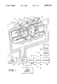
- FIG. 1 is a diagrammatic illustration of a magnetic resonance imaging apparatus incorporating the present invention
- FIG. 2 is a diagrammatic illustration of an RF coil section in accordance with the present invention.
- FIG. 3 is a general representation of a probe with two parallel coil sections
- FIG. 4 is a representation of a probe with two series coil sections
- FIG. 5 is an illustration of a magnetic resonance probe with a combination of series and parallel connected coil sections
- FIG. 6 illustrates a saddle coil electrical diagram of the probe of FIG. 1
- FIG. 6A is an end view of the saddle coil of FIG. 6;
- FIG. 7 is an enlarged view of the probe of FIG. 1 illustrating the removability of a top portion
- FIG. 8 is an electrical diagram of the bottom half of the probe of FIG. 7;
- FIG. 9 is another alternate embodiment, ideally suited for cervical spin studies.
- FIG. 10 is an equivalent circuit diagram of a coil section.
- a magnetic resonance imaging apparatus includes a magnetic field means A for generating magnetic fields and magnetic field gradients through an image of an examination region 10.
- a plurality of superconducting, resistive, or permanent magnets 12 create a substantially uniform, static magnetic field through the image region.
- a main magnetic field controller 14 controls superconducting and resistive magnets to optimize field uniformity.
- Gradient field coils 16 under the control of a gradient field controller 18 selectively cause magnetic field gradients across the image region. Commonly, gradients of selectable slope are selectively applied along one or more mutually orthogonal axes having an apex adjacent a center of the image region.
- a resonance means B excites, manipulates, and recovers magnetic resonance of selected dipoles within the image region. More specifically, a radio frequency transmitter 20 selectively applies current pulses to a resonator probe 22 to excite selected dipoles in the image region to resonate or to tip or rotate the magnetization of resonating nuclei.
- the probe 22 functions as an antenna for a radio frequency receiver 24 to receive radio frequency magnetic resonance signals emanating from the resonating nuclei.
- An image reconstruction means C reconstructs an image representation from the received magnetic resonance signals.
- a transform means 30 applies a two dimensional inverse Fourier transform or other appropriate transform to each received magnetic resonance signal to generate transformed views.
- An image memory 32 accumulates the transformed views into an image representation. The completed image representation can be displayed on a video monitor 34, stored on tape or disk, subject to further processing, or the like.
- An imaging sequence control means 36 controls the gradient field control means 18, the radio frequency transmitter 20, and other circuit components such that the imager implements a selected one of the many known magnetic resonance imaging sequences.
- the probe 22 includes at least one coil section that has a plurality n of conductor branches, 40 0 -40 n .
- the conductor branches may lie in two or three dimensions.
- a tuning reactance 42 such as capacitor C t is connected across the feed points 44, 46 of the coil section to adjust the resonant frequency of the coil to the Larmor frequency.
- the conductor branches include a plurality of reactances 48, particularly capacitors C 1 -C n . The capacitors are selected so that the current I 0 -I n through each of the branches matches a precalculated current distribution.
- the Biot-Savart Law dictates the current flow through each of the conductor branches.
- Each conductor branch has a self capacitance, as well as a mutual inductance with adjoining branches.
- the reactance of the self and mutual inductances and the capacitors determines the relative current flow through each of the conductor branches.
- the capacitors C 1 -C n are selected to adjust the reactances of each branch such that the resultant currents I 0 -I n match the currents prescribed by the Biot-Savart Law.
- two or more coil sections 50, 52 may be connected in parallel to provide more current branches for improved uniformity in the image region.
- the two sections have a two fold or planar symmetry.
- two or more coil sections may be connected in series. Again, the sections are preferably arranged with two fold symmetry.
- four of the coil sections 50, 52, 54, 56 are connected in a combination of parallel and series. More specifically to the illustrated embodiment, two pair of series connected coils are connected in parallel. For design simplicity, four fold symmetry is preferred.
- the probe 22 of the preferred embodiment is a saddle coil with four coil sections 50, 52, 54, and 56.
- Coil sections 50 and 52 are connected in series as are sections 54 and 56. The two series connected pairs are connected in parallel about the feed points 44, 46.
- each coil section has two conductor branches offset from a horizontal axis by angles ⁇ 0 and ⁇ 1 through which currents I 0 and I 1 flow, respectively.
- An adjustable reactance preferably a capacitor C 0 , is connected with the two conductor branches for adjusting the ratio of the current flow therethrough.
- the reactance means is a capacitor in one of the branches or conductors.
- the capacitor is adjusted to achieve the relative current flow designated by the Biot-Savart Law.
- the field may be monitored and the capacitor iteratively adjusted until the uniformity of the field within the coil is optimized.
- the tuning capacitor C t across the feed points adjusts the resonance frequency of the probe.
- the probe 22 includes two probe portions 60, 62, each of which extends generally around a half cylinder.
- a pair of electrical connectors 64 interconnect the two probe portions.
- the top probe portion which is above the patient's face, is relatively open so as to be less claustrophobic.
- An open window 66 is defined in the center of the top portion and is open over 90° or more of arc. While window 66 provides openness in front of the patient's face, it's 90° span prevents the eight conductor branches of the preferred embodiment from being arranged symmetrically at like angles around the cylinder.
- the top portion 60 of the coil is selectively removable, which enables the lower coil probe portion 62 to function as a neck and cervical spin coil.
- a reactive module 68 is connected with the connectors 64 in place of the top coil portion 60 to electrically connect an inductive/capacitive reactive load in place of the removed top coil segment.
- the reactive load of the reactive module 68 is selected to present the same reactance to the lower probe segment as the top coil segment presented. The reactive module maintains current continuity, tuning of the coil, and field uniformity without readjustment.
- two series connected coils sections 70 and 72 are connected across the feed points 44, 46. Each section has three conductors or branches connected in parallel.
- the capacitors C 1 , C 2 are selected such that the current flows I 0 , I 1 , and I 2 match the current flows predicted to create the optimum field uniformity in the region of interest. Alternately, the capacitors may be adjusted iteratively by monitoring the uniformity of the magnetic field in the region of interest and adjusting the capacitors until the field uniformity is optimized.
- the capacitor C t resonates the probe or coil at a frequency ⁇ .
- the ratio between the currents I 0 , I 1 , . . . , I n would be determined by geometry-dependent branch impedances.
- the impedance determined current distribution does not necessarily yield a desired field uniformity in the imaging region.
- this method first determines the currents I 0 , I 1 , . . . , I n which produces the optimum field distribution and then selects the capacitors C 1 , C 2 . . . , C n which causes the current to be divided among the branches such that the selected current distribution is achieved.
- the current distribution is determined by a straight forward application of the Biot-Savart Law. In case of a circularly cylindrical coil volume, an angular cosine function for the currents yields optimum field uniformity. Numerical optimization techniques may also be utilized in some geometries.
- each of the coil branches has a self inductance L n and a mutual inductance with adjoining coils M mn (m ⁇ n).
- the equivalent circuit is illustrated in FIG. 10.
- a ratio ⁇ n of the current in the nth branch I n , to the current in the first branch, I 0 , is: ##EQU1##
- the self impedance x n of each branch is: ##EQU2##
- the mutual inductance X mn between branches is:
- the self and mutual inductances of the coil branches are measured first without the capacitor C n .
- the self inductance of each coil is measured with the other branches disconnected, e.g. an open circuit where the capacitor is to be inserted.
- the mutual inductance M mn between branches M and N can be calculated based on Ohm's Law: ##EQU8## where L m and L n are self inductances of coils and L cmn is the inductance of the two branches in parallel.
- the capacitance by Equations 4 and 5
- the capacitance is: ##EQU9## With four fold symmetry, all four sections 50, 52, 54, 56 can be analyzed analogously.
- the capacitance C 1 is calculated from Equation (10) to be 49 pF.
Landscapes
- Physics & Mathematics (AREA)
- Condensed Matter Physics & Semiconductors (AREA)
- General Physics & Mathematics (AREA)
- Magnetic Resonance Imaging Apparatus (AREA)
Priority Applications (4)
| Application Number | Priority Date | Filing Date | Title |
|---|---|---|---|
| US07/392,653 US5045792A (en) | 1985-08-14 | 1989-08-11 | Split and non-circular magnetic resonance probes with optimum field uniformity |
| DE69026552T DE69026552T2 (de) | 1989-08-11 | 1990-08-06 | Magnetische Resonanz-Sonden |
| EP90308619A EP0412749B1 (fr) | 1989-08-11 | 1990-08-06 | Sondes de résonance magnétique |
| JP2211462A JP2909600B2 (ja) | 1989-08-11 | 1990-08-08 | 磁気共鳴プローブ及びその製造法 |
Applications Claiming Priority (2)
| Application Number | Priority Date | Filing Date | Title |
|---|---|---|---|
| US06/765,708 US4793356A (en) | 1985-08-14 | 1985-08-14 | Surface coil system for magnetic resonance imaging |
| US07/392,653 US5045792A (en) | 1985-08-14 | 1989-08-11 | Split and non-circular magnetic resonance probes with optimum field uniformity |
Related Parent Applications (2)
| Application Number | Title | Priority Date | Filing Date |
|---|---|---|---|
| US07/199,202 Continuation-In-Part US4879516A (en) | 1985-08-14 | 1988-05-26 | Precision electrical adjustment of quadrature coil isolation |
| US07/234,278 Continuation-In-Part US4918388A (en) | 1985-08-14 | 1988-08-19 | Quadrature surface coils for magnetic resonance imaging |
Related Child Applications (1)
| Application Number | Title | Priority Date | Filing Date |
|---|---|---|---|
| US07/651,306 Continuation-In-Part US5144240A (en) | 1985-08-14 | 1991-02-06 | Nmr spectroscopy and imaging coil |
Publications (1)
| Publication Number | Publication Date |
|---|---|
| US5045792A true US5045792A (en) | 1991-09-03 |
Family
ID=23551477
Family Applications (1)
| Application Number | Title | Priority Date | Filing Date |
|---|---|---|---|
| US07/392,653 Expired - Lifetime US5045792A (en) | 1985-08-14 | 1989-08-11 | Split and non-circular magnetic resonance probes with optimum field uniformity |
Country Status (4)
| Country | Link |
|---|---|
| US (1) | US5045792A (fr) |
| EP (1) | EP0412749B1 (fr) |
| JP (1) | JP2909600B2 (fr) |
| DE (1) | DE69026552T2 (fr) |
Cited By (22)
| Publication number | Priority date | Publication date | Assignee | Title |
|---|---|---|---|---|
| US5144239A (en) * | 1989-08-16 | 1992-09-01 | Siemens Aktiengesellschaft | Circularly polarizing rf antenna for an mri apparatus |
| US5168230A (en) * | 1990-08-17 | 1992-12-01 | General Electric | Dual frequency nmr surface coil pair with interleaved lobe areas |
| US5210494A (en) * | 1989-07-05 | 1993-05-11 | Max-Planck-Gesellschaft Zur Forderung Der Wissenschaften E.V. | Sample head for nuclear magnetic resonance whole-body tomography or localized in-vivo nuclear magnetic resonance spectroscopy |
| US5221902A (en) * | 1990-10-22 | 1993-06-22 | Medical Advances, Inc. | NMR neck coil with passive decoupling |
| US5343148A (en) * | 1991-12-20 | 1994-08-30 | Bruker Analytische Messtechnik Gmbh | Gradient coil system |
| US5347220A (en) * | 1991-12-11 | 1994-09-13 | U.S. Philips Corporation | Magnetic resonance apparatus comprising a bird-cage RF coil |
| US5457387A (en) * | 1993-07-06 | 1995-10-10 | Picker International, Inc. | Magnetic resonance imager with removable element RF coil |
| US5510714A (en) * | 1991-08-09 | 1996-04-23 | Hitachi, Ltd. | Magnetic resonance imaging apparatus and RF coil employed therein |
| US5564421A (en) * | 1991-04-04 | 1996-10-15 | Instrumentarium Corporation | VHF applicator for magnetic resonance imaging |
| US5585724A (en) * | 1995-06-12 | 1996-12-17 | Picker International, Inc. | Magnetic resonance gradient coils with interstitial gap |
| US5696449A (en) * | 1996-06-03 | 1997-12-09 | General Electric Company | RF coil for open MR magnet |
| US5898306A (en) * | 1997-04-09 | 1999-04-27 | Regents Of The University Of Minnesota | Single circuit ladder resonator quadrature surface RF coil |
| WO2002010786A3 (fr) * | 2000-07-31 | 2002-06-13 | Univ Minnesota | Unite a champ magnetique radiofrequence |
| US6535084B1 (en) * | 2000-01-15 | 2003-03-18 | Ge Medical Systems Global Technology Company, Llc | Method and apparatus for designing an RF coil assembly |
| US6633161B1 (en) | 1999-05-21 | 2003-10-14 | The General Hospital Corporation | RF coil for imaging system |
| EP1521094A1 (fr) * | 2003-10-01 | 2005-04-06 | Gore Enterprise Holdings, Inc. | Réseau modulaire de bobines HF d'IRM |
| WO2007049167A3 (fr) * | 2005-10-28 | 2007-10-25 | Koninkl Philips Electronics Nv | Bobines radiofrequence specifiques de regions d'imagerie pour l'imagerie par resonance magnetique |
| US20080084210A1 (en) * | 2004-05-07 | 2008-04-10 | Regents Of The University Of Minnesota | Multi-current elements for magnetic resonance radio frequency coils |
| US7598739B2 (en) | 1999-05-21 | 2009-10-06 | Regents Of The University Of Minnesota | Radio frequency gradient, shim and parallel imaging coil |
| CN104422913A (zh) * | 2013-09-03 | 2015-03-18 | 西门子公司 | 组合的匀场和高频线圈元件 |
| EP3081953A3 (fr) * | 2015-04-15 | 2017-02-22 | Bruker BioSpin AG | Systeme de bobine de reception et d'emission nmr |
| EP3646810A1 (fr) * | 2018-11-02 | 2020-05-06 | Biosense Webster (Israel) Ltd. | Transmetteurs magnétiques pour système de suivi magnétique |
Families Citing this family (4)
| Publication number | Priority date | Publication date | Assignee | Title |
|---|---|---|---|---|
| US5280248A (en) * | 1992-07-24 | 1994-01-18 | Picker International, Inc. | Biplanar RF coil for magnetic resonance imaging systems |
| DE4019046A1 (de) * | 1990-06-15 | 1991-12-19 | Philips Patentverwaltung | Oberflaechenspule fuer kernresonanzuntersuchungen |
| US5602479A (en) * | 1995-08-08 | 1997-02-11 | Picker International, Inc. | Quadrature radio frequency coil for magnetic resonance imaging |
| US7602188B2 (en) * | 2004-07-29 | 2009-10-13 | Koninklijke Philips Electronics N.V. | System of electric coils for transmitting and receiving radio-frequency magnetic fields in a magnetic-resonance imaging apparatus, and magnetic-resonance imaging apparatus provided with such a system of electric coils |
Citations (15)
| Publication number | Priority date | Publication date | Assignee | Title |
|---|---|---|---|---|
| GB2145230A (en) * | 1983-08-12 | 1985-03-20 | Picker Int Ltd | Nuclear magnetic resonance apparatus |
| EP0142760A2 (fr) * | 1983-11-14 | 1985-05-29 | General Electric Company | Bobine à sections multiples couplée inductivement à champ haute fréquence pour la résonance magnétique nucléaire |
| US4591818A (en) * | 1983-12-23 | 1986-05-27 | Picker International Limited | Coil arrangement for generating a high frequency magnetic field |
| US4607225A (en) * | 1983-07-19 | 1986-08-19 | Regents Of The University Of California | Apparatus and method for reducing spurious currents in NMR imaging apparatus induced by pulsed gradient fields |
| US4665368A (en) * | 1985-04-16 | 1987-05-12 | Yokogawa Hokushin Electric Corporation | NMR imaging apparatus |
| US4680548A (en) * | 1984-10-09 | 1987-07-14 | General Electric Company | Radio frequency field coil for NMR |
| US4694255A (en) * | 1983-11-04 | 1987-09-15 | General Electric Company | Radio frequency field coil for NMR |
| US4820987A (en) * | 1986-12-22 | 1989-04-11 | U.S. Philips Corporation | Magnetic resonance imaging apparatus comprising an activatable birdcage RF coil |
| US4845432A (en) * | 1986-12-03 | 1989-07-04 | U.S. Philips Corporation | Gradient coil for a magnetic resonance imaging apparatus |
| US4845613A (en) * | 1984-11-08 | 1989-07-04 | Elscint Ltd. | Radio frequency excitation and gradient pulse controller having plurality of channels for transmitting instruction and Rf pulse pattern data to a magnetic resonance imaging system |
| US4845431A (en) * | 1988-03-18 | 1989-07-04 | University Of Pittsburgh | Variable aperture, variable frequency extremity coil for magnetic resonance imaging |
| US4845430A (en) * | 1986-06-30 | 1989-07-04 | Kabushiki Kaisha Toshiba | Magnetic resonance imaging system |
| US4844077A (en) * | 1985-07-10 | 1989-07-04 | Hitachi, Ltd. | NMR imaging method |
| US4899108A (en) * | 1987-08-21 | 1990-02-06 | Fuji Electric Co., Ltd. | High frequency coil |
| US4906933A (en) * | 1988-03-18 | 1990-03-06 | Elscint Ltd. | Quadrature surface coil |
Family Cites Families (5)
| Publication number | Priority date | Publication date | Assignee | Title |
|---|---|---|---|---|
| GB2151791A (en) * | 1983-12-23 | 1985-07-24 | Gen Electric | RF Field coils for NMR apparatus |
| NL8402380A (nl) * | 1984-07-30 | 1986-02-17 | Philips Nv | Kernspin resonantie apparaat met een zend-meetspoel voor hoge frequenties. |
| US4634980A (en) * | 1984-08-16 | 1987-01-06 | Picker International, Inc. | Nuclear magnetic resonance radio frequency antenna |
| US4638253A (en) * | 1984-10-29 | 1987-01-20 | General Electric Company | Mutual inductance NMR RF coil matching device |
| EP0389868B1 (fr) * | 1989-03-29 | 1995-09-13 | Siemens Aktiengesellschaft | Tomographe par spins nucléaires |
-
1989
- 1989-08-11 US US07/392,653 patent/US5045792A/en not_active Expired - Lifetime
-
1990
- 1990-08-06 EP EP90308619A patent/EP0412749B1/fr not_active Expired - Lifetime
- 1990-08-06 DE DE69026552T patent/DE69026552T2/de not_active Expired - Fee Related
- 1990-08-08 JP JP2211462A patent/JP2909600B2/ja not_active Expired - Fee Related
Patent Citations (15)
| Publication number | Priority date | Publication date | Assignee | Title |
|---|---|---|---|---|
| US4607225A (en) * | 1983-07-19 | 1986-08-19 | Regents Of The University Of California | Apparatus and method for reducing spurious currents in NMR imaging apparatus induced by pulsed gradient fields |
| GB2145230A (en) * | 1983-08-12 | 1985-03-20 | Picker Int Ltd | Nuclear magnetic resonance apparatus |
| US4694255A (en) * | 1983-11-04 | 1987-09-15 | General Electric Company | Radio frequency field coil for NMR |
| EP0142760A2 (fr) * | 1983-11-14 | 1985-05-29 | General Electric Company | Bobine à sections multiples couplée inductivement à champ haute fréquence pour la résonance magnétique nucléaire |
| US4591818A (en) * | 1983-12-23 | 1986-05-27 | Picker International Limited | Coil arrangement for generating a high frequency magnetic field |
| US4680548A (en) * | 1984-10-09 | 1987-07-14 | General Electric Company | Radio frequency field coil for NMR |
| US4845613A (en) * | 1984-11-08 | 1989-07-04 | Elscint Ltd. | Radio frequency excitation and gradient pulse controller having plurality of channels for transmitting instruction and Rf pulse pattern data to a magnetic resonance imaging system |
| US4665368A (en) * | 1985-04-16 | 1987-05-12 | Yokogawa Hokushin Electric Corporation | NMR imaging apparatus |
| US4844077A (en) * | 1985-07-10 | 1989-07-04 | Hitachi, Ltd. | NMR imaging method |
| US4845430A (en) * | 1986-06-30 | 1989-07-04 | Kabushiki Kaisha Toshiba | Magnetic resonance imaging system |
| US4845432A (en) * | 1986-12-03 | 1989-07-04 | U.S. Philips Corporation | Gradient coil for a magnetic resonance imaging apparatus |
| US4820987A (en) * | 1986-12-22 | 1989-04-11 | U.S. Philips Corporation | Magnetic resonance imaging apparatus comprising an activatable birdcage RF coil |
| US4899108A (en) * | 1987-08-21 | 1990-02-06 | Fuji Electric Co., Ltd. | High frequency coil |
| US4845431A (en) * | 1988-03-18 | 1989-07-04 | University Of Pittsburgh | Variable aperture, variable frequency extremity coil for magnetic resonance imaging |
| US4906933A (en) * | 1988-03-18 | 1990-03-06 | Elscint Ltd. | Quadrature surface coil |
Non-Patent Citations (1)
| Title |
|---|
| IEEE Standard Dictionary of Electrical and Electronics Terms; Third Edition, Editor, F. Jay, p. 516, 1984. * |
Cited By (43)
| Publication number | Priority date | Publication date | Assignee | Title |
|---|---|---|---|---|
| US5210494A (en) * | 1989-07-05 | 1993-05-11 | Max-Planck-Gesellschaft Zur Forderung Der Wissenschaften E.V. | Sample head for nuclear magnetic resonance whole-body tomography or localized in-vivo nuclear magnetic resonance spectroscopy |
| US5144239A (en) * | 1989-08-16 | 1992-09-01 | Siemens Aktiengesellschaft | Circularly polarizing rf antenna for an mri apparatus |
| US5168230A (en) * | 1990-08-17 | 1992-12-01 | General Electric | Dual frequency nmr surface coil pair with interleaved lobe areas |
| US5221902A (en) * | 1990-10-22 | 1993-06-22 | Medical Advances, Inc. | NMR neck coil with passive decoupling |
| US5564421A (en) * | 1991-04-04 | 1996-10-15 | Instrumentarium Corporation | VHF applicator for magnetic resonance imaging |
| US5510714A (en) * | 1991-08-09 | 1996-04-23 | Hitachi, Ltd. | Magnetic resonance imaging apparatus and RF coil employed therein |
| US5347220A (en) * | 1991-12-11 | 1994-09-13 | U.S. Philips Corporation | Magnetic resonance apparatus comprising a bird-cage RF coil |
| US5343148A (en) * | 1991-12-20 | 1994-08-30 | Bruker Analytische Messtechnik Gmbh | Gradient coil system |
| US5457387A (en) * | 1993-07-06 | 1995-10-10 | Picker International, Inc. | Magnetic resonance imager with removable element RF coil |
| US5585724A (en) * | 1995-06-12 | 1996-12-17 | Picker International, Inc. | Magnetic resonance gradient coils with interstitial gap |
| US5696449A (en) * | 1996-06-03 | 1997-12-09 | General Electric Company | RF coil for open MR magnet |
| US5898306A (en) * | 1997-04-09 | 1999-04-27 | Regents Of The University Of Minnesota | Single circuit ladder resonator quadrature surface RF coil |
| US7598739B2 (en) | 1999-05-21 | 2009-10-06 | Regents Of The University Of Minnesota | Radio frequency gradient, shim and parallel imaging coil |
| US20070247160A1 (en) * | 1999-05-21 | 2007-10-25 | The General Hospital Corporation D/B/A Massachusetts General Hospital | Rf coil for imaging system |
| US6633161B1 (en) | 1999-05-21 | 2003-10-14 | The General Hospital Corporation | RF coil for imaging system |
| US7268554B2 (en) | 1999-05-21 | 2007-09-11 | The General Hospital Corporation | RF coil for imaging system |
| US20070007964A1 (en) * | 1999-05-21 | 2007-01-11 | The General Hospital Corporation D/B/A Massachusetts General Hospital | RF coil for imaging system |
| US20060033501A1 (en) * | 1999-05-21 | 2006-02-16 | The General Hospital Corporation D/B/A Massachusetts General Hospital | RF coil for imaging system |
| US6535084B1 (en) * | 2000-01-15 | 2003-03-18 | Ge Medical Systems Global Technology Company, Llc | Method and apparatus for designing an RF coil assembly |
| US6958607B2 (en) | 2000-07-31 | 2005-10-25 | Regents Of The University Of Minnesota | Assymetric radio frequency transmission line array |
| US20060001426A1 (en) * | 2000-07-31 | 2006-01-05 | Regents Of The University Of Minnesota | Assymetric radio frequency magnetic line array |
| US20060255806A1 (en) * | 2000-07-31 | 2006-11-16 | Regents Of The University Of Minnesota | Assymetric radio frequency magnetic line array |
| US6788056B2 (en) | 2000-07-31 | 2004-09-07 | Regents Of The University Of Minnesota | Radio frequency magnetic field unit with aperature |
| US20040027128A1 (en) * | 2000-07-31 | 2004-02-12 | Regents Of The University Of Minnesota | Radio frequency magnetic field unit |
| EP2034325A1 (fr) * | 2000-07-31 | 2009-03-11 | Regents of the University of Minnesota | Resonateurs ouverts en mode tem pour l'irm |
| US7893693B2 (en) | 2000-07-31 | 2011-02-22 | Regents Of The University Of Minnesota | Assymetric radio frequency magnetic line array |
| WO2002010786A3 (fr) * | 2000-07-31 | 2002-06-13 | Univ Minnesota | Unite a champ magnetique radiofrequence |
| US20050073309A1 (en) * | 2003-10-01 | 2005-04-07 | Williams Neil R. | Magnetic resonance coil modules |
| EP1521094A1 (fr) * | 2003-10-01 | 2005-04-06 | Gore Enterprise Holdings, Inc. | Réseau modulaire de bobines HF d'IRM |
| US20080084210A1 (en) * | 2004-05-07 | 2008-04-10 | Regents Of The University Of Minnesota | Multi-current elements for magnetic resonance radio frequency coils |
| US7710117B2 (en) | 2004-05-07 | 2010-05-04 | Regents Of The University Of Minnesota | Multi-current elements for magnetic resonance radio frequency coils |
| US20080284436A1 (en) * | 2005-10-28 | 2008-11-20 | Koninklijke Philips Electronics N. V. | Imaging Region-Specific Radio Frequency Coils for Mri |
| US7728591B2 (en) | 2005-10-28 | 2010-06-01 | Koninklijke Philips Electronics N.V. | Imaging region-specific radio frequency coils for MRI |
| WO2007049167A3 (fr) * | 2005-10-28 | 2007-10-25 | Koninkl Philips Electronics Nv | Bobines radiofrequence specifiques de regions d'imagerie pour l'imagerie par resonance magnetique |
| US9864023B2 (en) | 2013-09-03 | 2018-01-09 | Siemens Aktiengesellschaft | Combined shim and RF coil arrangement |
| CN104422913A (zh) * | 2013-09-03 | 2015-03-18 | 西门子公司 | 组合的匀场和高频线圈元件 |
| CN104422913B (zh) * | 2013-09-03 | 2018-02-16 | 西门子公司 | 组合的匀场和高频线圈元件 |
| EP3081953A3 (fr) * | 2015-04-15 | 2017-02-22 | Bruker BioSpin AG | Systeme de bobine de reception et d'emission nmr |
| US10310034B2 (en) | 2015-04-15 | 2019-06-04 | Bruker Biospin Ag | NMR transmitting/receiving coil configuration |
| EP3646810A1 (fr) * | 2018-11-02 | 2020-05-06 | Biosense Webster (Israel) Ltd. | Transmetteurs magnétiques pour système de suivi magnétique |
| JP2020069402A (ja) * | 2018-11-02 | 2020-05-07 | バイオセンス・ウエブスター・(イスラエル)・リミテッドBiosense Webster (Israel), Ltd. | 磁気追跡システム用磁気送信機 |
| US10928465B2 (en) | 2018-11-02 | 2021-02-23 | Biosense Webster (Israel) Ltd. | Magnetic transmitters for a magnetic tracking system |
| JP2024083512A (ja) * | 2018-11-02 | 2024-06-21 | バイオセンス・ウエブスター・(イスラエル)・リミテッド | 磁気追跡システム用磁気送信機 |
Also Published As
| Publication number | Publication date |
|---|---|
| DE69026552T2 (de) | 1996-10-31 |
| DE69026552D1 (de) | 1996-05-23 |
| EP0412749A2 (fr) | 1991-02-13 |
| EP0412749B1 (fr) | 1996-04-17 |
| JP2909600B2 (ja) | 1999-06-23 |
| EP0412749A3 (en) | 1991-09-18 |
| JPH03149033A (ja) | 1991-06-25 |
Similar Documents
| Publication | Publication Date | Title |
|---|---|---|
| US5045792A (en) | Split and non-circular magnetic resonance probes with optimum field uniformity | |
| US4740751A (en) | Whole body MRI resonator | |
| US6396271B1 (en) | Tunable birdcage transmitter coil | |
| US7495443B2 (en) | RF coil system for super high field (SHF) MRI | |
| EP0301232B1 (fr) | Bobine de surface à deux fréquences, pour la RMN | |
| US8049504B2 (en) | Simple decoupling of a multi-element RF coil, enabling also detuning and matching functionality | |
| EP0201084B1 (fr) | Sonde locale utilisée en imagerie par résonance magnétique nucléaire | |
| US10451692B2 (en) | Multi-resonant T/R antenna for MR image generation | |
| US5990681A (en) | Low-cost, snap-in whole-body RF coil with mechanically switchable resonant frequencies | |
| US5689189A (en) | Technique for designing distributed radio frequency coils and distributed radio frequency coils designed thereby | |
| US5680047A (en) | Multipl-tuned radio frequency coil for simultaneous magnetic resonance imaging and spectroscopy | |
| US4721913A (en) | NMR local coil network | |
| US6043658A (en) | MR apparatus including an MR coil system | |
| US6054858A (en) | Method to automatically tune MRI RF coils | |
| US6538441B1 (en) | RF coil for reduced electric field exposure for use in very high field magnetic resonance imaging | |
| US6791328B1 (en) | Method and apparatus for very high field magnetic resonance imaging systems | |
| US4752738A (en) | Three dimensional localized coil for magnetic resonance imaging | |
| CN101526593A (zh) | 用于对磁共振成像的射频检测器阵列去耦的方法和设备 | |
| US5585721A (en) | Inductively coupled dedicated RF coils for MRI | |
| US6822448B2 (en) | RF coil for very high field magnetic resonance imaging | |
| US5329233A (en) | Cylindrical local coil for nuclear magnetic resonance imaging | |
| EP3577479B1 (fr) | Alimentation inductive d'une bobine rf pour imagerie par résonance magnétique | |
| US4797617A (en) | Nuclear magnetic resonance radio frequency antenna | |
| US20230078150A1 (en) | Double-resonant coil, array of double-resonant coils, and use thereof | |
| US4731584A (en) | Magnetic resonance probe for operation at frequencies above self resonance |
Legal Events
| Date | Code | Title | Description |
|---|---|---|---|
| AS | Assignment |
Owner name: PICKER INTERNATIONAL, INC., OHIO Free format text: ASSIGNMENT OF ASSIGNORS INTEREST.;ASSIGNOR:MEHDIZADEH, MEHRDAD;REEL/FRAME:005114/0779 Effective date: 19890810 |
|
| STCF | Information on status: patent grant |
Free format text: PATENTED CASE |
|
| FPAY | Fee payment |
Year of fee payment: 4 |
|
| FPAY | Fee payment |
Year of fee payment: 8 |
|
| FPAY | Fee payment |
Year of fee payment: 12 |