US5049094A - Fixing device for fixing a terminal block on a symmetrical mounting rail - Google Patents
Fixing device for fixing a terminal block on a symmetrical mounting rail Download PDFInfo
- Publication number
- US5049094A US5049094A US07/662,134 US66213491A US5049094A US 5049094 A US5049094 A US 5049094A US 66213491 A US66213491 A US 66213491A US 5049094 A US5049094 A US 5049094A
- Authority
- US
- United States
- Prior art keywords
- hook
- fastening piece
- blade spring
- rod
- fixing
- Prior art date
- Legal status (The legal status is an assumption and is not a legal conclusion. Google has not performed a legal analysis and makes no representation as to the accuracy of the status listed.)
- Expired - Lifetime
Links
- 239000002184 metal Substances 0.000 claims description 2
- 230000006835 compression Effects 0.000 description 2
- 238000007906 compression Methods 0.000 description 2
Images
Classifications
-
- H—ELECTRICITY
- H02—GENERATION; CONVERSION OR DISTRIBUTION OF ELECTRIC POWER
- H02B—BOARDS, SUBSTATIONS OR SWITCHING ARRANGEMENTS FOR THE SUPPLY OR DISTRIBUTION OF ELECTRIC POWER
- H02B1/00—Frameworks, boards, panels, desks, casings; Details of substations or switching arrangements
- H02B1/015—Boards, panels, desks; Parts thereof or accessories therefor
- H02B1/04—Mounting thereon of switches or of other devices in general, the switch or device having, or being without, casing
- H02B1/052—Mounting on rails
Definitions
- the invention relates to fixing a terminal block onto a symmetrical rail.
- Fixing devices include hooks to enable the apparatus to be installed on or removed from the mounting rail.
- the fastening piece comprises a rod and a body which slide along a longitudinal guide in the base of the case.
- the partially-comressed compression spring is fitted in a housing made in the base and has the rod of the fastening piece passing therethrough, said rod co-operating with the body to form shoulders.
- the end of the rod is fitted with a pin which compresses the spring when the apparatus is mounted on a rail.
- the fastening piece includes two hooks for fixing onto rails, and a guide which cooperates with a groove in the base in order to hold the fastening piece captive. Because it moves in the base of the case, such a fastening piece may not be used as an earthing connection to connect the mounting rail to earth.
- An object of the invention is to provide a terminal block fixing device which can also be used as an earthing connection.
- the present invention provides a fixing device for fixing a terminal block on a symmetrical rail, the device being situated on a base of an insulating case of the terminal block and including a metal fastening piece and a spring, the fastening piece including a body, first and second rigid hooks under the body, and a rod, the first hook being situated at the opposite end of the body to the rod, the second hook being situated at the other end of the body, and the base including a longitudinal slot in its bottom portion, wherein:
- the body has a third hook and a stop between the first and second hooks, the third hook being nearer to the second hook and the stop being nearer to the first hook;
- the spring is a blade spring constituted by two sub-blades separated by a slot and interconnected by first and second bridges situated at respective ends of the blade spring;
- said blade spring has an arched portion followed by a curved portion bent back towards the convex side of the arched portion;
- the rod is connected to the body by a connection zone including a tooth above the body;
- the blade spring has its second bridge located at the end of the arched part, said second bridge cooperating with the third hook and the first bridge cooperating with said tooth to fix the blade spring onto the fastening part.
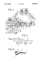
- FIG. 1 shows a device of the invention mounted on a symmetrical rail
- FIG. 2 shows a fastening piece of the FIG. 1 device
- FIG. 3 is a perspective view of a spring of the FIG. 1 device.
- FIG. 1 shows a fixing device of the invention mounted on a symmetrical rail P.
- the fixing device is constituted by a base 1 of a case B of an apparatus to be fixed, a fastening piece 2, and a blade spring 3.
- the case B has terminals C1 and C2 for electrical connections and in its middle it has two other terminals C11 and C12; the number of terminals on the case is independent of the invention.
- the base 1 of the case includes a lug 5 which forms a corner with the bottom face 7 of the base, said corner facing the opposite edge of the base, and receiving a rim 30 of the symmetrical rail P.
- the base includes a fixed portion 15 and a moving portion 16, connected by hinges 19 to the fixed portion, the hinges being made of the same plastic as the case B and being integrally molded therewith, as is the moving portion 16.
- the fixed and moving portions are identical and include ribs 20, 21, 22, 23 on the fixed portion and 20', 21', 22', 23' on the moving portion. Studs 24, 25, 26 on the moving portion cooperate with holes 27, 28, 29 in the fixed portion to fix the moving portion on the fixed portion.
- the ribs have gaps 31, 32, 33, which can be seen on the moving portion, for receiving and fixing the fastening piece 2.
- the fastening piece 2 includes a body 11 and a rod 12.
- the body 11 On its bottom, the body 11 includes a first hook 13, located at the opposite end of the body to the rod, and a second hook 14 located at the other end of the body. Between the first and second hooks, the body has a third hook 17 and a stop 18, the third hook being nearer the second hook 14 and the stop being nearer the first hook 13.
- the top of the fastening piece has a notch 10 which cooperates with a tooth 9 on the base to stop any longitudinal movement of the fastening piece in the base 1, in whose bottom portion there is a longitudinal slot made in the thickness of the base to house the hook 13 and that portion of the body 11 which lies between the stop 18 and said hook 13.
- the rod 12 is offset relative to the body 11 and it extends parallel thereto from the top end thereof, constituting a kind of extension to the body 11.
- the rod and the body are thus connected by a connection zone 8 which includes a tooth 38 whose end 39, facing the top of the body and inclined relative thereto, is used as a rest for the blade spring 3.
- This blade spring shown in perspective FIG. 3, is constituted by two sub-blades 41, 42 interconnected by two bridges 43, 44, one at each end of the blade spring; the sub-blades are separated by a slot 45.
- the blade spring includes an arched portion 46 ending in the bridge 44 and a curved portion 47 bent back towards the convex side of the arched portion and including the bridge 43.
- the blade spring is mounted onto the fastening piece as follows: with the blade spring practically perpendicular to the body 11, the first hook 13 is engaged in the slot 45, the bridge 44 is engaged between the third hook 17 and the stop 18, and the blade spring is moved back towards the end of the body 11 nearest the rod 12; the body moves into the slot 45 until the bridge 43 of the curved portion 47 comes into contact with the top of the body. In this position, the tooth 44 is parallel to the bottom of the body and is trapped in the space between the third hook 17, the stop 18 and said bottom, since the width of the tooth 44 is greater than that of the space 52 between the third hook 17 and the stop 18.
- the first hook 13 of the fastening piece now fitted with its blade spring is inserted into the longitudinal slot of the bottom portion 4 of the base 1.
- the notch 10 in the body cooperates with the tooth 9 on the base; the connection zone 8 fits into the gaps 31 and 32, and the rod 12 fits into the gap 33.
- the curved portion 47 of the blade spring fits into a housing delimited by the ribs 20 and 20', by the wall 50 of the fixed portion 15, and by the wall 51 of the moving portion 16.
- the rod 12 is fixed to an earthing terminal CM which enables the rail P to be connected to earth via the fastening piece 2 which, in the present invention, is fixed in the base of the case.
- the contact established between the fastening piece 2 and the rail via the rail rims 30 and 34 and the hooks 13 and 14, is improved by contact teeth 49 situated on the bottom of the fastening part 2, near the notch 35, said contact teeth 49 bearing against the rim 34 of the rail P.
Landscapes
- Engineering & Computer Science (AREA)
- Power Engineering (AREA)
- Connections Arranged To Contact A Plurality Of Conductors (AREA)
- Clamps And Clips (AREA)
- Lift-Guide Devices, And Elevator Ropes And Cables (AREA)
Applications Claiming Priority (2)
| Application Number | Priority Date | Filing Date | Title |
|---|---|---|---|
| FR9002651 | 1990-03-02 | ||
| FR9002651A FR2659118B1 (fr) | 1990-03-02 | 1990-03-02 | Dispositif de fixation d'un bloc de jonction sur un profile support symetrique. |
Publications (1)
| Publication Number | Publication Date |
|---|---|
| US5049094A true US5049094A (en) | 1991-09-17 |
Family
ID=9394321
Family Applications (1)
| Application Number | Title | Priority Date | Filing Date |
|---|---|---|---|
| US07/662,134 Expired - Lifetime US5049094A (en) | 1990-03-02 | 1991-02-28 | Fixing device for fixing a terminal block on a symmetrical mounting rail |
Country Status (6)
| Country | Link |
|---|---|
| US (1) | US5049094A (de) |
| EP (1) | EP0444565B1 (de) |
| JP (1) | JP2846970B2 (de) |
| DE (1) | DE69106741T2 (de) |
| ES (1) | ES2067782T3 (de) |
| FR (1) | FR2659118B1 (de) |
Cited By (17)
| Publication number | Priority date | Publication date | Assignee | Title |
|---|---|---|---|---|
| US5388999A (en) * | 1992-11-20 | 1995-02-14 | Nozick; Jacques | Connection system using terminal strips for use in high bit rate communications |
| US5588881A (en) * | 1994-10-31 | 1996-12-31 | Weidmueller Interface Gmbh & Co. | Connector terminal block with electronic module |
| US5704805A (en) * | 1995-03-31 | 1998-01-06 | The Whitaker Corporation | Connector for connection to a rail |
| US6183311B1 (en) * | 1997-07-09 | 2001-02-06 | Wieland Electric Gmbh | Protective conductor clamp |
| US6471552B2 (en) * | 2000-01-04 | 2002-10-29 | Entrelec S.A. | Spring for securing a terminal block or the like to a rail |
| US20070049129A1 (en) * | 2005-08-26 | 2007-03-01 | Phoenix Contact Gmbh & Co. Kg | Electrical connecting terminal |
| US20070128921A1 (en) * | 2003-10-16 | 2007-06-07 | Moeller Gmbh | Contactor equipped with box terminals |
| US20080261426A1 (en) * | 2007-04-12 | 2008-10-23 | Joerg Diekmann | Terminal block with plug-in module |
| US20100134986A1 (en) * | 2006-12-07 | 2010-06-03 | Franz Hecht | Fastening device for electronic modules on a support rail |
| US20130280934A1 (en) * | 2012-04-20 | 2013-10-24 | Woehner Gmbh & Co. Kg Elektrotechnische Systeme | Carrier Rail Adapter |
| US20140226287A1 (en) * | 2011-08-30 | 2014-08-14 | Te Connectivity India Private Limited | Electrical component for rail mounting |
| US20160087355A1 (en) * | 2014-09-23 | 2016-03-24 | Abb Technology Ag | Part of a conducting bar for an electrical apparatus |
| EP3054531A1 (de) * | 2015-02-05 | 2016-08-10 | Morsettitalia S.p.A. | Erdleitungselement für schaltanlage klemmenleisten und zugehorige klemmenleiste für erdnungsdrähte |
| WO2017102764A1 (en) * | 2015-12-17 | 2017-06-22 | Te Connectivity Germany Gmbh | Rail socket with improved current transmission |
| EP3840141A1 (de) * | 2019-12-17 | 2021-06-23 | Connecteurs Electriques Deutsch | Klemmvorrichtung für eine tragschiene |
| US11239580B2 (en) * | 2018-04-24 | 2022-02-01 | Phoenix Contact Gmbh & Co. Kg | Plug-in connection arrangement for an electrical terminal block |
| US11418014B2 (en) * | 2020-05-30 | 2022-08-16 | Regal Beloit America, Inc. | Retractable DIN clip |
Families Citing this family (4)
| Publication number | Priority date | Publication date | Assignee | Title |
|---|---|---|---|---|
| DE19530924C2 (de) * | 1995-08-23 | 2001-11-08 | Huber Signalbau Ag | Vorrichtung zur Erdung einer modular aufgebauten Gehäuseeinheit |
| DE19631436C1 (de) * | 1996-08-03 | 1997-10-09 | Weidmueller Interface | Schutzleiteranschluß insbesondere für Reihenklemmen |
| DE10249981B3 (de) * | 2002-10-26 | 2004-04-01 | Moeller Gmbh | Elektronische Steuereinrichtung mit Mitteln zur Ableitung von Störsignalen |
| JP4540037B2 (ja) * | 2003-11-25 | 2010-09-08 | 日東工業株式会社 | プラグインユニット |
Citations (6)
| Publication number | Priority date | Publication date | Assignee | Title |
|---|---|---|---|---|
| DE1490769A1 (de) * | 1962-09-26 | 1969-06-19 | Telemecanique Electrique | Elektrische Anschlussklemme mit einer Einrichtung zu ihrer Befestigung an einem Traeger mit C-foermigem Querschnitt |
| US4220392A (en) * | 1978-02-07 | 1980-09-02 | Societe Anonyme Dite: Cgee Alsthom | Terminal block for ground conductors |
| US4268108A (en) * | 1978-11-06 | 1981-05-19 | Cgee Alsthom | Locking arrangement for fixing a terminal block |
| US4454382A (en) * | 1981-03-23 | 1984-06-12 | Cgee Alsthom | Structure for fixing a device on a supporting channel bar |
| DE3526494A1 (de) * | 1985-07-24 | 1987-01-29 | Siemens Ag | Schutzleiteranschlussklemme |
| EP0233458B1 (de) * | 1986-01-23 | 1991-06-26 | Siemens Aktiengesellschaft | Schutzleiteranschlussklemme |
-
1990
- 1990-03-02 FR FR9002651A patent/FR2659118B1/fr not_active Expired - Lifetime
-
1991
- 1991-02-25 ES ES91102718T patent/ES2067782T3/es not_active Expired - Lifetime
- 1991-02-25 EP EP91102718A patent/EP0444565B1/de not_active Expired - Lifetime
- 1991-02-25 DE DE69106741T patent/DE69106741T2/de not_active Expired - Fee Related
- 1991-02-28 US US07/662,134 patent/US5049094A/en not_active Expired - Lifetime
- 1991-03-01 JP JP3059520A patent/JP2846970B2/ja not_active Expired - Fee Related
Patent Citations (6)
| Publication number | Priority date | Publication date | Assignee | Title |
|---|---|---|---|---|
| DE1490769A1 (de) * | 1962-09-26 | 1969-06-19 | Telemecanique Electrique | Elektrische Anschlussklemme mit einer Einrichtung zu ihrer Befestigung an einem Traeger mit C-foermigem Querschnitt |
| US4220392A (en) * | 1978-02-07 | 1980-09-02 | Societe Anonyme Dite: Cgee Alsthom | Terminal block for ground conductors |
| US4268108A (en) * | 1978-11-06 | 1981-05-19 | Cgee Alsthom | Locking arrangement for fixing a terminal block |
| US4454382A (en) * | 1981-03-23 | 1984-06-12 | Cgee Alsthom | Structure for fixing a device on a supporting channel bar |
| DE3526494A1 (de) * | 1985-07-24 | 1987-01-29 | Siemens Ag | Schutzleiteranschlussklemme |
| EP0233458B1 (de) * | 1986-01-23 | 1991-06-26 | Siemens Aktiengesellschaft | Schutzleiteranschlussklemme |
Cited By (26)
| Publication number | Priority date | Publication date | Assignee | Title |
|---|---|---|---|---|
| US5388999A (en) * | 1992-11-20 | 1995-02-14 | Nozick; Jacques | Connection system using terminal strips for use in high bit rate communications |
| US5588881A (en) * | 1994-10-31 | 1996-12-31 | Weidmueller Interface Gmbh & Co. | Connector terminal block with electronic module |
| US5704805A (en) * | 1995-03-31 | 1998-01-06 | The Whitaker Corporation | Connector for connection to a rail |
| US6183311B1 (en) * | 1997-07-09 | 2001-02-06 | Wieland Electric Gmbh | Protective conductor clamp |
| US6471552B2 (en) * | 2000-01-04 | 2002-10-29 | Entrelec S.A. | Spring for securing a terminal block or the like to a rail |
| DE10100182B4 (de) * | 2000-01-04 | 2006-12-14 | Entrelec Sa | Feder zur Befestigung einer Reihenklemme an einer Schiene |
| US20070128921A1 (en) * | 2003-10-16 | 2007-06-07 | Moeller Gmbh | Contactor equipped with box terminals |
| US7281959B2 (en) * | 2003-10-16 | 2007-10-16 | Moeller Gmbh | Contactor equipped with box terminals |
| US20070049129A1 (en) * | 2005-08-26 | 2007-03-01 | Phoenix Contact Gmbh & Co. Kg | Electrical connecting terminal |
| US7192316B1 (en) * | 2005-08-26 | 2007-03-20 | Phoenix Contact Gmbh & Co., Kg | Electrical connecting terminal |
| US20100134986A1 (en) * | 2006-12-07 | 2010-06-03 | Franz Hecht | Fastening device for electronic modules on a support rail |
| US8325491B2 (en) * | 2006-12-07 | 2012-12-04 | Siemens Aktiengesellschaft | Fastening device for electronic modules on a support rail |
| US20080261426A1 (en) * | 2007-04-12 | 2008-10-23 | Joerg Diekmann | Terminal block with plug-in module |
| US7658653B2 (en) * | 2007-04-12 | 2010-02-09 | Weidmuller Interface Gmbh & Co. Kg | Terminal block with plug-in module |
| US9653891B2 (en) * | 2011-08-30 | 2017-05-16 | Te Connectivity India Private Limited | Electrical component for rail mounting |
| US20140226287A1 (en) * | 2011-08-30 | 2014-08-14 | Te Connectivity India Private Limited | Electrical component for rail mounting |
| US20130280934A1 (en) * | 2012-04-20 | 2013-10-24 | Woehner Gmbh & Co. Kg Elektrotechnische Systeme | Carrier Rail Adapter |
| US9118124B2 (en) * | 2012-04-20 | 2015-08-25 | Woehner Gmbh & Co. Kg | Carrier rail adapter |
| US20160087355A1 (en) * | 2014-09-23 | 2016-03-24 | Abb Technology Ag | Part of a conducting bar for an electrical apparatus |
| US9698503B2 (en) * | 2014-09-23 | 2017-07-04 | Abb Schweiz Ag | Part of a conducting bar for an electrical apparatus |
| EP3054531A1 (de) * | 2015-02-05 | 2016-08-10 | Morsettitalia S.p.A. | Erdleitungselement für schaltanlage klemmenleisten und zugehorige klemmenleiste für erdnungsdrähte |
| US9806479B2 (en) | 2015-02-05 | 2017-10-31 | Morsettitalia S.P.A. | Earthing conductor element for switchboard terminal blocks and associated terminal block for earthing earth wires |
| WO2017102764A1 (en) * | 2015-12-17 | 2017-06-22 | Te Connectivity Germany Gmbh | Rail socket with improved current transmission |
| US11239580B2 (en) * | 2018-04-24 | 2022-02-01 | Phoenix Contact Gmbh & Co. Kg | Plug-in connection arrangement for an electrical terminal block |
| EP3840141A1 (de) * | 2019-12-17 | 2021-06-23 | Connecteurs Electriques Deutsch | Klemmvorrichtung für eine tragschiene |
| US11418014B2 (en) * | 2020-05-30 | 2022-08-16 | Regal Beloit America, Inc. | Retractable DIN clip |
Also Published As
| Publication number | Publication date |
|---|---|
| ES2067782T3 (es) | 1995-04-01 |
| EP0444565A1 (de) | 1991-09-04 |
| FR2659118B1 (fr) | 1992-05-07 |
| DE69106741D1 (de) | 1995-03-02 |
| JPH04218273A (ja) | 1992-08-07 |
| FR2659118A1 (fr) | 1991-09-06 |
| DE69106741T2 (de) | 1995-05-18 |
| JP2846970B2 (ja) | 1999-01-13 |
| EP0444565B1 (de) | 1995-01-18 |
Similar Documents
| Publication | Publication Date | Title |
|---|---|---|
| US5049094A (en) | Fixing device for fixing a terminal block on a symmetrical mounting rail | |
| KR0159509B1 (ko) | 전기코넥터 스티프너기구 | |
| US4591228A (en) | Mechanical fastening device for assembling electrical equipment modules | |
| US4454382A (en) | Structure for fixing a device on a supporting channel bar | |
| JPH056795B2 (de) | ||
| EP0718932A2 (de) | Vorrichtung zum Niederhalten auf Leiterplatten montierten Verbindern | |
| US4113982A (en) | Means for mounting on channel-section supporting rails | |
| EP0886353A2 (de) | Verbesserungen in bezug auf Unterbrecher und Versorgungseinrichtungen | |
| KR100261912B1 (ko) | 단락회로 브리지를 가진 플러그 커넥터 | |
| KR880013271A (ko) | 전화기 모듈형 잭 | |
| US20060099849A1 (en) | Connection device for flexible circuit | |
| KR940006310A (ko) | 전기 스프링 접촉자 | |
| US4032739A (en) | Supporting structure for leaf spring contact assembly | |
| US5775482A (en) | Snap-in mount for plunger switch | |
| KR100269562B1 (ko) | 모듈 지지구조의 앞쪽 모듈 레일과 인쇄회로기판의 전기적 접촉을 위한 접촉소자 | |
| US6916214B2 (en) | Connecting terminal | |
| KR940020619A (ko) | 절연체 제거 전기 단자 조립체(Insulation displacement electrical terminal assembly) | |
| KR20080000640A (ko) | 접속 터미널용 클램핑 장치 | |
| JP2000100297A (ja) | 機器取付ベース | |
| US3430190A (en) | Terminal block mounting | |
| US3953699A (en) | Fastening arrangement for the switching mechanism cage of an electric switching apparatus | |
| JPH05236615A (ja) | 屋外用電気機器収納ボックスの防塵構造 | |
| SU957446A1 (ru) | Разъемное соединение деталей | |
| KR19990077298A (ko) | 스위치캐비닛내부에설치된어셈블리패널을도전접속하기위한장치_ | |
| GB2140981A (en) | Electrical connector |
Legal Events
| Date | Code | Title | Description |
|---|---|---|---|
| AS | Assignment |
Owner name: ENTRELEC S.A.,, FRANCE Free format text: ASSIGNMENT OF ASSIGNORS INTEREST.;ASSIGNORS:HENG, JEAN-PAUL;BIDAL, JEAN-CLAUDE;PREDIGNAC, MICHEL;REEL/FRAME:005765/0929 Effective date: 19910204 |
|
| STCF | Information on status: patent grant |
Free format text: PATENTED CASE |
|
| FEPP | Fee payment procedure |
Free format text: PAYOR NUMBER ASSIGNED (ORIGINAL EVENT CODE: ASPN); ENTITY STATUS OF PATENT OWNER: LARGE ENTITY |
|
| FEPP | Fee payment procedure |
Free format text: PAYER NUMBER DE-ASSIGNED (ORIGINAL EVENT CODE: RMPN); ENTITY STATUS OF PATENT OWNER: LARGE ENTITY Free format text: PAYOR NUMBER ASSIGNED (ORIGINAL EVENT CODE: ASPN); ENTITY STATUS OF PATENT OWNER: LARGE ENTITY |
|
| FPAY | Fee payment |
Year of fee payment: 4 |
|
| FPAY | Fee payment |
Year of fee payment: 8 |
|
| FPAY | Fee payment |
Year of fee payment: 12 |