US5067362A - Control device - Google Patents
Control device Download PDFInfo
- Publication number
- US5067362A US5067362A US07/445,843 US44584389A US5067362A US 5067362 A US5067362 A US 5067362A US 44584389 A US44584389 A US 44584389A US 5067362 A US5067362 A US 5067362A
- Authority
- US
- United States
- Prior art keywords
- annular space
- valve
- transmission
- shifting piston
- position shifting
- Prior art date
- Legal status (The legal status is an assumption and is not a legal conclusion. Google has not performed a legal analysis and makes no representation as to the accuracy of the status listed.)
- Expired - Fee Related
Links
- 230000005540 biological transmission Effects 0.000 claims abstract description 55
- 238000009313 farming Methods 0.000 claims description 9
- 238000007789 sealing Methods 0.000 claims description 6
- 239000007858 starting material Substances 0.000 claims description 3
- 238000013022 venting Methods 0.000 claims description 3
- 230000008878 coupling Effects 0.000 claims 8
- 238000010168 coupling process Methods 0.000 claims 8
- 238000005859 coupling reaction Methods 0.000 claims 8
- 230000007935 neutral effect Effects 0.000 description 4
- 238000010586 diagram Methods 0.000 description 2
- 238000010276 construction Methods 0.000 description 1
- 238000006073 displacement reaction Methods 0.000 description 1
Images




Classifications
-
- F—MECHANICAL ENGINEERING; LIGHTING; HEATING; WEAPONS; BLASTING
- F16—ENGINEERING ELEMENTS AND UNITS; GENERAL MEASURES FOR PRODUCING AND MAINTAINING EFFECTIVE FUNCTIONING OF MACHINES OR INSTALLATIONS; THERMAL INSULATION IN GENERAL
- F16H—GEARING
- F16H63/00—Control outputs from the control unit to change-speed- or reversing-gearings for conveying rotary motion or to other devices than the final output mechanism
- F16H63/40—Control outputs from the control unit to change-speed- or reversing-gearings for conveying rotary motion or to other devices than the final output mechanism comprising signals other than signals for actuating the final output mechanisms
- F16H63/44—Signals to the control unit of auxiliary gearing
-
- Y—GENERAL TAGGING OF NEW TECHNOLOGICAL DEVELOPMENTS; GENERAL TAGGING OF CROSS-SECTIONAL TECHNOLOGIES SPANNING OVER SEVERAL SECTIONS OF THE IPC; TECHNICAL SUBJECTS COVERED BY FORMER USPC CROSS-REFERENCE ART COLLECTIONS [XRACs] AND DIGESTS
- Y10—TECHNICAL SUBJECTS COVERED BY FORMER USPC
- Y10T—TECHNICAL SUBJECTS COVERED BY FORMER US CLASSIFICATION
- Y10T74/00—Machine element or mechanism
- Y10T74/19—Gearing
- Y10T74/19219—Interchangeably locked
- Y10T74/19251—Control mechanism
-
- Y—GENERAL TAGGING OF NEW TECHNOLOGICAL DEVELOPMENTS; GENERAL TAGGING OF CROSS-SECTIONAL TECHNOLOGIES SPANNING OVER SEVERAL SECTIONS OF THE IPC; TECHNICAL SUBJECTS COVERED BY FORMER USPC CROSS-REFERENCE ART COLLECTIONS [XRACs] AND DIGESTS
- Y10—TECHNICAL SUBJECTS COVERED BY FORMER USPC
- Y10T—TECHNICAL SUBJECTS COVERED BY FORMER US CLASSIFICATION
- Y10T74/00—Machine element or mechanism
- Y10T74/20—Control lever and linkage systems
- Y10T74/20012—Multiple controlled elements
- Y10T74/20018—Transmission control
- Y10T74/2014—Manually operated selector [e.g., remotely controlled device, lever, push button, rotary dial, etc.]
- Y10T74/20159—Control lever movable through plural planes
Definitions
- the invention relates to a control device for a gearbox of group design. More particularly the invention relates to a transmission of group design, primarily for a farm tractor, wherein at least the gears of a standard transmission are changed mechanically by hand according to a standard H shifting pattern and an additional shifting is effected in two forward drive groups and one reverse drive group.
- Such devices or as shown in FIGS. 1 and 2, with a gear splitting that can be shifted up or down under load of the gears 1 to 4, have proven to be successful in farm tractors.
- Another object is to provide such a control system which requires no intervention in the gearbox and which permits the gears of the main gearbox to continue to be shifted mechanically so that it is possible to equip already existing farm tractors with the device.
- This object is attained, according to the invention, in that a road travel gear group (S) and a farming operation group (A), as well as a reverse group (R) are engaged by means of a servo control on the manual gear lever for the gears in the standard transmission.
- a gear-shift mechanism is arranged on the gearbox, this mechanism consisting of an electro-hydraulic control unit, a power-assisted servo control for shifting the groups and a transmission system for the gears in the basic transmission shifted manually according to an H-type shifting pattern.
- the servo control has solenoid valves, and a selector slide is permanently connected with a pressure source and is displaced by the pressure medium into two respective end positions and one middle position.
- a selector slide is permanently connected with a pressure source and is displaced by the pressure medium into two respective end positions and one middle position.
- one of the solenoid valves is assigned.
- a two-position shifting piston for the engagement and disengagement of the road travel group (S) and a three-position shifting piston for the farming operation group (A) and a reverse group (R), as well as a middle- and a zero-position are shifted via a control valve and a shift lever.
- a pressure-cutoff valve is assigned to each end position of the two-position shifting piston which also has a command slide valve assigned to it.
- a command slide valve is assigned and to each end position, a pressure-cutoff valve can be assigned. For venting both piston spaces in the middle position both two-way valves are shifted.
- the electric and hydraulic connections of the gearshift mechanism can be achieved over flexible lines and the actuation connections for the mechanical shifting by hand can basically remain unchanged and therefore are easily connectable.
- only two shifting pistons are provided in the gear-shifting mechanism and all the slide valves and other valves, including the solenoid valves, are arranged in one electrohydraulic control unit, with a control-unit case and a cover designed as a channel plate for the pressure ducts.
- the oil or pressure ducts in the cover of the control-unit case are very short.
- FIG. 1 is a perspective view of a gear-changing device with shifting console in the driver's cabin and a gearshift mechanism on the gearbox;
- FIG. 2 schematic representation of the speed-changing gearbox
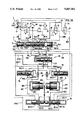
- FIGS. 3 and 3A are control diagrams for the shifting of the groups
- FIG. 4 is a section through the control-unit case of the electro-hydraulic control unit.
- FIG. 5 is an elevational view of the gearshift mechanism partially broken.
- FIG. 1 shows the shifting console 2 with the manual
- the manual gear-shift lever 23 for the mechanical shifting of the speeds in the basic transmission 11 is shiftable in the gear-shifting gate 21 according to an H-pattern, from the neutral position 210 in the paths of the gears G1/G2; G3/G4 and in the gears themselves.
- the manual gear lever 23 is connected in a known manner, via for instance transmission rods 51, with the transmission system 5.
- two levers 52, 53 which are rigidly connected with a shaft 54 and a hollow shaft 55 and two rods 51, assigned to the paths G1/G2; G3/G4, are represented.
- a servo-control 22 for the shifting of the transmission groups is also provided.
- the road travel group S and the reverse group R can be actuated (selected), via for instance an electrical switch, through three solenoid valves located in the control-unit case 31, whereby one solenoid valve is assigned to each group. This prevents a surprise shifting of the transmission groups, in case of power failure.
- a pressure-medium source, pump 64 drawing the pressure medium from a return receptacle, sump 13 of the gearbox case 12, in FIG. 2, is provided with a pressure-relief valve 640.
- the pump is connected via ducts 65, 66, 67 with the solenoid valves 61, 62, 63 and via ducts 68, 69 directly with the fourth and eighth annular spaces 76/4, 76/8 of the selector slide or spiral valve 7.
- the duct 620 leads from the solenoid valve 62 to the two outer annular spaces 76/1 and 76/12, the duct 610 leads form the solenoid valve 61 to the second annular space 76/2, and the duct 630 leads from the solenoid valve 63 to the eleventh annular space 76/11.
- the selector slide valve 7 has a central spool 73 with six plungers 731 to 736 and five recesses of various length arranged between the plunger 5, as well as two external spools 74, 75, each with only one plunger 741, 751 and one collar 742, 752, reaching into the outer annular spaces 76/1 and 76/12.
- a three-position shifting piston 9 is pushed into the left end position by a control valve 91 and a shift lever 92, and a two-position shifting piston 8 (FIG. 3) is directly pushed into the open position (right end position).
- the median position of the three-position shifting piston 9 is associated with the left end position of the selector slide 7 and the two-position shifting piston 8 is brought into the engaged position- left end position.
- the three-position shifting piston is also brought into the right end position by the pressure medium, and the two-position shifting piston 8 has already earlier been moved into the open position--right end position.
- their pressure spaces are vented.
- a command slide valve 81 and two pressure-cutoff valves 82, 83 are provided, and in connection with the three-position shifting piston 9, the control valve 91 connected therewith via shift lever 92, a command slide valve 93, as well as two pressure-cutoff valves 94, 95 and thereto assigned two-way valves 96, 97 are provided.
- the command slide valves 81, 93, pressure-cutoff valves 82, 83, 94, 95 and two-way valves 96, 97 and the shifting pistons 8, 9 and between each other the following connections exist over the pressure ducts:
- the solenoid valves 61, 62, 63, as well as the selector slide 7, the control valve 91 and the command slide valves 81, 93 and the pressure-cutoff valves 82, 93, 94, 95 are arranged.
- the shift lever 92 shown in FIG. 3A engages in the groove 914 in the sleeve valve 912, between the plungers 913/2 and 913/3.
- the mechanically acting emergency actuators 71, 72 are also provided on the selector slide 7, on both sides. With their help it is possible to shift the selector slide 7, in case of power failure or of failure of the solenoid valves.
- a positioning screw 710 is mounted, which by means of a sleeve 711 an a safety lock 712 is secured against unintentional turning.
- the mechanical emergency device comprises transmission pins 713 one for each of the positioning screws, the pins being held frontally flush by a second safety lock 714 against the action of a spring 715 in an offset bore of the respective outer sleeve valve 74, 75.
- the middle sleeve valve 73 can be brought into the middle position--which corresponds to shifting into the farming-operation group--when the two positioning screws push the extreme sleeve valves 74, 75 to stop against collars 742, 752 thereof.
- the gearshift mechanism according to FIG. 5, which is flanged on the gearbox case 12, comprises the electro-hydraulic control unit 3, the servo control 4 and the transmission system 5 for the mechanical shifting of the gears.
- the solenoid valves are protected by a cover 34. In the cover 32, all the ducts shown in FIG.
- the transmission system 5 is also located, which over two levers 52, 53, transmits the shifting motion coming from the transmission rods 51 for the gears G1 to G4, via the hollow shaft 55 and the shaft 54, to the clutches G1 to G4.
- an electrical-mechanical starter safeguard 56 is also provided.
- a surface 560 is provided and in the same plane, the hollow shaft 55 is slotted--slot 561--up to this surface.
- a sensor 563 cooperating with a switch 562 is located in slot 561 and in the neutral position 210 of the shift lever 23 extends into the slot up to the surface 560, since both levers 52, 53 are in the middle position.
- a plug marked 36 serves for the connection of the electrical leads 25, 26, 27 from the shifting console 2 with the solenoid valves 61, 62, 63.
- circularly running relief channels 38, 39 coming from the control-unit case 31 and from the cover 32 are provided, which have a connection to the inner space 410 of the gearbox case, collect the leaked oil and discharge it into this inner space.
- the entire inner space and also the vented pressure spaces of the shifting pistons are filled with oil, because the overflow passage 46 to the sump 13 is placed very high up, for instance in the form of an enlarged passage opening for the hollow shaft 42.
Landscapes
- Engineering & Computer Science (AREA)
- General Engineering & Computer Science (AREA)
- Mechanical Engineering (AREA)
- Gear-Shifting Mechanisms (AREA)
- Control Of Transmission Device (AREA)
- Arrangement Or Mounting Of Control Devices For Change-Speed Gearing (AREA)
Applications Claiming Priority (2)
| Application Number | Priority Date | Filing Date | Title |
|---|---|---|---|
| DE3717935 | 1987-05-27 | ||
| DE3717935 | 1987-05-27 |
Publications (1)
| Publication Number | Publication Date |
|---|---|
| US5067362A true US5067362A (en) | 1991-11-26 |
Family
ID=6328572
Family Applications (1)
| Application Number | Title | Priority Date | Filing Date |
|---|---|---|---|
| US07/445,843 Expired - Fee Related US5067362A (en) | 1987-05-27 | 1988-05-18 | Control device |
Country Status (6)
| Country | Link |
|---|---|
| US (1) | US5067362A (de) |
| EP (1) | EP0367768B1 (de) |
| JP (1) | JPH02503590A (de) |
| DE (1) | DE3862030D1 (de) |
| ES (1) | ES2007211A6 (de) |
| WO (1) | WO1988009452A1 (de) |
Cited By (8)
| Publication number | Priority date | Publication date | Assignee | Title |
|---|---|---|---|---|
| US5417124A (en) * | 1991-11-08 | 1995-05-23 | Iveco Fiat S.P.A. | Gear change for an industrial vehicle provided with an integrated control unit |
| US5747960A (en) * | 1993-07-08 | 1998-05-05 | Saulo Quaggio | Computer controlled gearshift with automatic clutch actuator for vehicles with manual gearboxes |
| US5810448A (en) * | 1995-01-09 | 1998-09-22 | Diamant Boart, Inc. | Self propelled saw |
| US6647821B2 (en) * | 2000-12-07 | 2003-11-18 | Deere & Company | Transmission shift lever assembly |
| US20050010289A1 (en) * | 1998-01-28 | 2005-01-13 | Mckernan Daniel J. | Method and apparatus for fixing a graft in a bone tunnel |
| US20060183597A1 (en) * | 2005-02-11 | 2006-08-17 | Dominique Szymczak | Transmission controllers |
| US20140251053A1 (en) * | 2011-08-01 | 2014-09-11 | Yasushi Yamamoto | Multistage transmission gear shift method, multistage transmission gear shift operation device, and vehicle mounted with same |
| PL126571U1 (pl) * | 2017-09-04 | 2019-03-11 | Wojskowe Zakłady Motoryzacyjne Spółka Akcyjna | Mechanizm awaryjnego sterowania skrzynią biegów |
Families Citing this family (2)
| Publication number | Priority date | Publication date | Assignee | Title |
|---|---|---|---|---|
| GB9221205D0 (en) * | 1992-10-08 | 1992-11-25 | Massey Ferguson Sa | Transmission units |
| WO2010089424A1 (es) | 2009-02-09 | 2010-08-12 | Uralita Iberia S.L. | Sistema constructivo para tabiquería seca con recubrimiento cerámico |
Citations (8)
| Publication number | Priority date | Publication date | Assignee | Title |
|---|---|---|---|---|
| US2582895A (en) * | 1949-10-19 | 1952-01-15 | Ernest R Sternberg | Dual transmission control |
| DE1951428A1 (de) * | 1969-10-11 | 1971-04-22 | Kloeckner Humboldt Deutz Ag | Verfahren und Einrichtung zum Schalten eines mehrstufigen Zahnradwechselgetriebes |
| US3757598A (en) * | 1971-06-21 | 1973-09-11 | Massey Ferguson Inc | Single lever control for transmission |
| EP0052794A2 (de) * | 1980-11-25 | 1982-06-02 | Deere & Company | Schaltvorrichtung für den Antrieb eines Nutzfahrzeuges |
| EP0071353A2 (de) * | 1981-07-27 | 1983-02-09 | Eaton Corporation | Halb-gesperrtes Getriebe |
| EP0122014A2 (de) * | 1983-03-15 | 1984-10-17 | Massey-Ferguson Services N.V. | Vorrichtung zum Wählen des Übersetzungsverhältnisses |
| US4483210A (en) * | 1980-12-26 | 1984-11-20 | Harutaka Mayuzumi | Multiple stage speed change gear device |
| US4905530A (en) * | 1988-09-29 | 1990-03-06 | Dr. Ing. H.C.F. Porsche Ag | Shifting arrangement for an automatic transmissdion of a motor vehicle |
-
1988
- 1988-04-26 ES ES8801269A patent/ES2007211A6/es not_active Expired
- 1988-05-18 EP EP88904220A patent/EP0367768B1/de not_active Expired - Lifetime
- 1988-05-18 DE DE8888904220T patent/DE3862030D1/de not_active Expired - Lifetime
- 1988-05-18 JP JP88504085A patent/JPH02503590A/ja active Pending
- 1988-05-18 US US07/445,843 patent/US5067362A/en not_active Expired - Fee Related
- 1988-05-18 WO PCT/EP1988/000424 patent/WO1988009452A1/de not_active Ceased
Patent Citations (9)
| Publication number | Priority date | Publication date | Assignee | Title |
|---|---|---|---|---|
| US2582895A (en) * | 1949-10-19 | 1952-01-15 | Ernest R Sternberg | Dual transmission control |
| DE1951428A1 (de) * | 1969-10-11 | 1971-04-22 | Kloeckner Humboldt Deutz Ag | Verfahren und Einrichtung zum Schalten eines mehrstufigen Zahnradwechselgetriebes |
| US3757598A (en) * | 1971-06-21 | 1973-09-11 | Massey Ferguson Inc | Single lever control for transmission |
| EP0052794A2 (de) * | 1980-11-25 | 1982-06-02 | Deere & Company | Schaltvorrichtung für den Antrieb eines Nutzfahrzeuges |
| US4483210A (en) * | 1980-12-26 | 1984-11-20 | Harutaka Mayuzumi | Multiple stage speed change gear device |
| EP0071353A2 (de) * | 1981-07-27 | 1983-02-09 | Eaton Corporation | Halb-gesperrtes Getriebe |
| EP0122014A2 (de) * | 1983-03-15 | 1984-10-17 | Massey-Ferguson Services N.V. | Vorrichtung zum Wählen des Übersetzungsverhältnisses |
| US4590817A (en) * | 1983-03-15 | 1986-05-27 | Massey-Ferguson Inc. | Gear selector means |
| US4905530A (en) * | 1988-09-29 | 1990-03-06 | Dr. Ing. H.C.F. Porsche Ag | Shifting arrangement for an automatic transmissdion of a motor vehicle |
Cited By (13)
| Publication number | Priority date | Publication date | Assignee | Title |
|---|---|---|---|---|
| US5417124A (en) * | 1991-11-08 | 1995-05-23 | Iveco Fiat S.P.A. | Gear change for an industrial vehicle provided with an integrated control unit |
| US5747960A (en) * | 1993-07-08 | 1998-05-05 | Saulo Quaggio | Computer controlled gearshift with automatic clutch actuator for vehicles with manual gearboxes |
| US5810448A (en) * | 1995-01-09 | 1998-09-22 | Diamant Boart, Inc. | Self propelled saw |
| US20050010289A1 (en) * | 1998-01-28 | 2005-01-13 | Mckernan Daniel J. | Method and apparatus for fixing a graft in a bone tunnel |
| US6647821B2 (en) * | 2000-12-07 | 2003-11-18 | Deere & Company | Transmission shift lever assembly |
| EP1717123A1 (de) * | 2005-02-11 | 2006-11-02 | Agco Sa | Getriebesteuerung |
| US20060183597A1 (en) * | 2005-02-11 | 2006-08-17 | Dominique Szymczak | Transmission controllers |
| EP2019012A1 (de) * | 2005-02-11 | 2009-01-28 | Agco Sa | Mehrfachgetriebe |
| US20090062996A1 (en) * | 2005-02-11 | 2009-03-05 | Agco Sa | Multi Ratio Transmission |
| US8311713B2 (en) | 2005-02-11 | 2012-11-13 | Agco Sa | Multi ratio transmission |
| US20140251053A1 (en) * | 2011-08-01 | 2014-09-11 | Yasushi Yamamoto | Multistage transmission gear shift method, multistage transmission gear shift operation device, and vehicle mounted with same |
| US9341259B2 (en) * | 2011-08-01 | 2016-05-17 | Isuzu Motors Limited | Multistage transmission gear shift operation device, and vehicle mounted with same |
| PL126571U1 (pl) * | 2017-09-04 | 2019-03-11 | Wojskowe Zakłady Motoryzacyjne Spółka Akcyjna | Mechanizm awaryjnego sterowania skrzynią biegów |
Also Published As
| Publication number | Publication date |
|---|---|
| JPH02503590A (ja) | 1990-10-25 |
| DE3862030D1 (de) | 1991-04-18 |
| EP0367768B1 (de) | 1991-03-13 |
| ES2007211A6 (es) | 1989-06-01 |
| EP0367768A1 (de) | 1990-05-16 |
| WO1988009452A1 (fr) | 1988-12-01 |
Similar Documents
| Publication | Publication Date | Title |
|---|---|---|
| US5038627A (en) | Vehicle transmission with manually shifted lower gears and automatically shifted upper gears | |
| US6568515B2 (en) | Hydraulic actuation systems | |
| EP0592170B1 (de) | Getriebeeinheit | |
| US3939722A (en) | Arrangement for controlling gear changes in a motor vehicle gear box | |
| US7730801B2 (en) | Servo-assisted control system for the gears of a single clutch gearbox of a motor vehicle | |
| EP1895204B1 (de) | Getriebeschaltung mit hydraulischer Hilfskraft | |
| US6658951B2 (en) | Hydraulic actuation systems | |
| US3946842A (en) | Electric and fluid controls for clutch and transmission | |
| US5067362A (en) | Control device | |
| US4633987A (en) | Pressure-medium actuated shifting arrangement | |
| US6886672B2 (en) | Power transmitting apparatus for a working vehicle | |
| EP0387275B1 (de) | Steuersystem für automatisches getriebe, in dem der gangwechsel stufenweise erfolgt | |
| US6637282B2 (en) | Hydraulic actuation systems | |
| US4666023A (en) | Transmission shifting arrangement | |
| US5239897A (en) | Automatic selector device for a multi-gear change-speed gearbox | |
| US5249476A (en) | Automatic selector device for multi-gear change-speed gearbox | |
| US20020046913A1 (en) | Hydraulic actuation systems | |
| GB2256243A (en) | An automatic selector device including a multi-way selection valve with stop means for a multi-gear change-speed gearbox | |
| US4674345A (en) | Automatic transmission having hydraulic and electronic control systems | |
| EP0412505B1 (de) | Hydraulische Steuerung einer Kupplung für ein industrielles Fahrzeug | |
| GB2369657A (en) | Automatic transmission hydraulic actuation system with separate gear engagement control valves | |
| US4560045A (en) | Transmission control system for a transmission having input shafts clutched to a power source | |
| DE3816926A1 (de) | Steuereinrichtung | |
| GB2360557A (en) | Transmission actuation system with actuators and valves having a common housing | |
| JPH0221645Y2 (de) |
Legal Events
| Date | Code | Title | Description |
|---|---|---|---|
| AS | Assignment |
Owner name: ZAHNRADFABRIK FRIEDRICHSHAFEN AG, GERMANY Free format text: ASSIGNMENT OF ASSIGNORS INTEREST.;ASSIGNOR:HOLDENRIED, WILLY;REEL/FRAME:005547/0144 Effective date: 19890921 |
|
| FEPP | Fee payment procedure |
Free format text: PAYOR NUMBER ASSIGNED (ORIGINAL EVENT CODE: ASPN); ENTITY STATUS OF PATENT OWNER: LARGE ENTITY |
|
| REMI | Maintenance fee reminder mailed | ||
| LAPS | Lapse for failure to pay maintenance fees | ||
| FP | Lapsed due to failure to pay maintenance fee |
Effective date: 19951129 |
|
| STCH | Information on status: patent discontinuation |
Free format text: PATENT EXPIRED DUE TO NONPAYMENT OF MAINTENANCE FEES UNDER 37 CFR 1.362 |