US5073763A - Group single-phase unidirectional transducers with 3/8λand 5/8λ sampling - Google Patents
Group single-phase unidirectional transducers with 3/8λand 5/8λ sampling Download PDFInfo
- Publication number
- US5073763A US5073763A US07/608,354 US60835490A US5073763A US 5073763 A US5073763 A US 5073763A US 60835490 A US60835490 A US 60835490A US 5073763 A US5073763 A US 5073763A
- Authority
- US
- United States
- Prior art keywords
- electrodes
- acoustic wave
- surface acoustic
- transducers
- transducer
- Prior art date
- Legal status (The legal status is an assumption and is not a legal conclusion. Google has not performed a legal analysis and makes no representation as to the accuracy of the status listed.)
- Expired - Lifetime
Links
Images


Classifications
-
- H—ELECTRICITY
- H03—ELECTRONIC CIRCUITRY
- H03H—IMPEDANCE NETWORKS, e.g. RESONANT CIRCUITS; RESONATORS
- H03H9/00—Networks comprising electromechanical or electro-acoustic elements; Electromechanical resonators
- H03H9/02—Details
- H03H9/125—Driving means, e.g. electrodes, coils
- H03H9/145—Driving means, e.g. electrodes, coils for networks using surface acoustic waves
- H03H9/14502—Surface acoustic wave [SAW] transducers for a particular purpose
- H03H9/14505—Unidirectional SAW transducers
-
- H—ELECTRICITY
- H03—ELECTRONIC CIRCUITRY
- H03H—IMPEDANCE NETWORKS, e.g. RESONANT CIRCUITS; RESONATORS
- H03H9/00—Networks comprising electromechanical or electro-acoustic elements; Electromechanical resonators
- H03H9/02—Details
- H03H9/125—Driving means, e.g. electrodes, coils
- H03H9/145—Driving means, e.g. electrodes, coils for networks using surface acoustic waves
- H03H9/14517—Means for weighting
-
- H—ELECTRICITY
- H03—ELECTRONIC CIRCUITRY
- H03H—IMPEDANCE NETWORKS, e.g. RESONANT CIRCUITS; RESONATORS
- H03H9/00—Networks comprising electromechanical or electro-acoustic elements; Electromechanical resonators
- H03H9/02—Details
- H03H9/125—Driving means, e.g. electrodes, coils
- H03H9/145—Driving means, e.g. electrodes, coils for networks using surface acoustic waves
- H03H9/14517—Means for weighting
- H03H9/1452—Means for weighting by finger overlap length, apodisation
-
- H—ELECTRICITY
- H03—ELECTRONIC CIRCUITRY
- H03H—IMPEDANCE NETWORKS, e.g. RESONANT CIRCUITS; RESONATORS
- H03H9/00—Networks comprising electromechanical or electro-acoustic elements; Electromechanical resonators
- H03H9/02—Details
- H03H9/125—Driving means, e.g. electrodes, coils
- H03H9/145—Driving means, e.g. electrodes, coils for networks using surface acoustic waves
- H03H9/14517—Means for weighting
- H03H9/14526—Finger withdrawal
-
- H—ELECTRICITY
- H03—ELECTRONIC CIRCUITRY
- H03H—IMPEDANCE NETWORKS, e.g. RESONANT CIRCUITS; RESONATORS
- H03H9/00—Networks comprising electromechanical or electro-acoustic elements; Electromechanical resonators
- H03H9/02—Details
- H03H9/125—Driving means, e.g. electrodes, coils
- H03H9/145—Driving means, e.g. electrodes, coils for networks using surface acoustic waves
- H03H9/14538—Formation
-
- H—ELECTRICITY
- H03—ELECTRONIC CIRCUITRY
- H03H—IMPEDANCE NETWORKS, e.g. RESONANT CIRCUITS; RESONATORS
- H03H9/00—Networks comprising electromechanical or electro-acoustic elements; Electromechanical resonators
- H03H9/02—Details
- H03H9/125—Driving means, e.g. electrodes, coils
- H03H9/145—Driving means, e.g. electrodes, coils for networks using surface acoustic waves
- H03H9/14544—Transducers of particular shape or position
- H03H9/14552—Transducers of particular shape or position comprising split fingers
Definitions
- the present invention relates in general to surface acoustic wave transducers and in particular to a new class of group-type single-phase unidirectional transducers (GSPUDTs) that can obtain unidirectional characteristics on conventional (CSPUDT) or natural (NSPUDT) crystal orientations.
- GSPUDTs group-type single-phase unidirectional transducers
- the sense of unidirectionality can be reversed by a simple change to the second level metalization.
- SAW devices Surface acoustic wave devices known as SAW devices have many uses in the UHF and VHF frequency ranges. SAW devices have been especially useful as impedance elements, resonators, and bandpass filters in these frequency ranges.
- Typical saw devices have a substrate with at least a surface layer of piezoelectric material and surface acoustic wave transducers in interdigitated form disposed on the piezoelectric surface. The transducers convert an electric signal to surface acoustic waves propagating on the piezoelectric surface.
- SAW devices are compact, lightweight, robust, and, because they are a planar technology, are economical to manufacture. They can be mass-produced using the same techniques developed so successfully for the production of silicon integrated circuits.
- a wide variety of analogue signal processing functions can be achieved with SAW devices.
- they are currently used in pulse compression radar systems as receiver bandpass filters, or as resonators for stabilizing oscillators in numerous applications. They have replaced many of the coils, capacitors, and metal cavities of conventional radio frequency systems, removing the need for hand alignment and dramatically improving the reliability and performance. They have simultaneously resulted in significant reductions in both size and cost.
- three-phase and single-phase devices are used to cause a greater amount of radiation in one direction in the crystal than in the reverse direction and thus form unidirectional transducers.
- SPUDT single-phase unidirectional transducer
- a device such as that disclosed in U.S. Pat. No. 4,353,046 is constructed in which the acoustic reflections are used to cancel the regenerative reflections and unidirectional behavior results.
- a low-loss filter with an NSPUDT and a group-type SPUDT (GSPUDT), such as the "Hopscotch” transducer.
- the filter function could then be implemented essentially by the NSPUDT, and the GSPUDT could simply be designed to have a sufficiently wide pass band and low loss.
- the undesired out-of-band group responses of the GSPUDT could be eliminated from the overall filter response by the NSPUDT.
- the "Hopscotch" GSPUDT configuration cannot be made unidirectional on an NSPUDT orientation. This is a consequence of the sampling in the structure.
- an alternative GSPUDT configuration would be required for this application.
- the present invention relates to GSPUDT structures with 3/8 ⁇ and 5/8 ⁇ sampling. Reflectionless or unidirectional transducers and broad-band notch elements are all implementable with these new configurations.
- the novel class of GSPUDTs disclosed herein is similar to the conventional SPUDT (CSPUDT) and the "Hopscotch" transducers in that single-level versions are reflectionless. Unidirectional characteristics are obtainable only from the two-level structure. However, in many cases they have significant advantages over either of the previous structures.
- the novel SAW transducers disclosed herein have a pattern of interdigitated electrodes on a piezoelectric substrate.
- the electrodes lie on the substrate on either a 3/8 ⁇ or 5/8 ⁇ grid such that adjacent electrodes have either a center-to-center spacing of 3/8 ⁇ or a center-to-center spacing of 5/8 ⁇ .
- the electrodes do not have to be physically located at every 3/8 ⁇ or 5/8 ⁇ grid.
- the transducer can be withdrawal weighted in a well-known manner in the art to achieve a desired transduction characteristic by actually removing various electrodes or by changing the polarity of certain electrodes.
- the important element of the invention is to have a 3/8 ⁇ or 5/8 ⁇ group type sampling which means that however the transducer is withdrawal weighted, the remaining electrodes are always centered on the 3/8 ⁇ or 5/8 ⁇ grid with any adjacent electrodes having either a 3/8 ⁇ or 5/8 ⁇ center-to-center spacing depending upon whether the transducer is a 3/8 ⁇ structure or a 5/8 ⁇ structure.
- the transducers will be shown and discussed with an electrode centered at each 3/8 ⁇ grid or at each 5/8 ⁇ grid.
- the physical structure includes a plurality of first pairs of interdigitated electrodes placed on a substrate with each first pair of electrodes having a center-to-center spacing of 3/8 ⁇ and reversed polarity from the preceding first pair.
- a plurality of second pairs of electrodes, each pair with a center-to-center spacing of 3/8 ⁇ , are interdigitated with the plurality of the first pairs of electrodes.
- Both electrodes in each second pair have a polarity opposite the polarity of, and a center-to-center spacing of 3/8 ⁇ with, the adjacent electrodes of a first pair.
- the pattern of the electrodes repeats itself each three wavelengths or each five wavelengths.
- the structure of the 5/8 ⁇ sampled GSPUDT is identical to the 3/8 ⁇ structure just disclosed except for the 5/8 ⁇ center-to-center spacing.
- Mass loading only one electrode of each of the second pair of electrodes and its adjacent first pair electrode obtains unidirectional transmission in one direction in the substrate.
- Mass loading only the other electrode of each of the second pair of electrodes and its adjacent first pair electrode obtains unidirectional transmission in the other direction in the substrate.
- novel transducers can be used on either NSPUDT crystal orientations or conventional crystal orientations because they can be made to radiate in either direction on either CSPUDT crystal orientations or NSPUDT crystal orientations, thus allowing filters, resonators and the like to be built on either conventional or CSPUDT crystal orientations or NSPUDT crystal orientations.
- the invention also relates to a surface acoustic wave transducer having a pattern of interdigitated electrodes on a piezoelectric substrate and comprising a plurality of first pairs of interdigitated electrodes, each said pair of electrodes having reversed polarity from the preceding first pair, a plurality of second pairs of electrodes interdigitated with said plurality of first pairs of electrodes, and both electrodes in each second pair having a polarity opposite the polarity of the adjacent first pair electrodes.
- the invention also relates to a surface acoustic wave filter of the type having input and output spaced aligned transducers with at least one of the transducers being the new GSPUDT transducer disclosed herein.
- FIG. 1A is a diagrammatic representation of a single-level reflectionless transducer of the present invention with a 3/8 ⁇ periodicity, the electrodes in FIG. 1A have a width of ⁇ /4 and the spaces separating each adjacent pair of electrodes are ⁇ /8 in width;
- FIG. 1B is a diagrammatic representation of a transducer identical to that illustrated in
- FIG. 1A except that the electrode widths are ⁇ /8 and the gaps separating adjacent electrodes are ⁇ /4. As in FIG. 1A, the periodicity or center-to-center spacing between adjacent electrodes is 3/8 ⁇ ;
- FIG. 1C is a schematic representation of a transducer identical to those in FIGS. 1A and 1B except that the electrode width is 3/16 ⁇ and the gap width separating adjacent electrodes is 3/16 ⁇ . Again, the periodicity is 3/8 ⁇ and the pattern repeats itself every three wavelengths;
- FIG. 1D is a schematic representation of the transducer of FIG. 1A with certain electrodes mass loaded or weighted to give a forward unidirectional transmission on a substrate with a conventional crystal orientation;
- FIG. 1E is a schematic representation of the transducer in FIG. 1A in which certain electrodes are weighted to give a reverse unidirectional transmission on a substrate with a conventional crystal orientation;
- FIG. 1F is a schematic representation of the transducer illustrated in FIG. 1A in which the proper electrodes have been mass weighted to obtain forward unidirectional transmission on a crystal substrate with an NSPUDT orientation;
- FIG. 1G is a schematic representation of the transducer structure in FIG. 1A illustrating the mass loading of the proper electrodes necessary to provide a reverse unidirectional transmission on a crystal substrate with an NSPUDT crystal orientation;
- FIG. 2A is a schematic representation of a transducer structure utilizing 5/8 ⁇ sampling or periodicity with a center-to-center spacing of 5/8 ⁇ between adjacent electrodes and illustrating that the transducer can be constructed with a 5 ⁇ grouping and 5/8 ⁇ periodicity by making the electrode widths either 3/8 ⁇ , 5/16 ⁇ or 1/4 ⁇ while making the corresponding gap widths 1/4 ⁇ , 5/16 ⁇ or 3/8 ⁇ , respectively;
- FIG. 2B is a schematic representation of the transducer illustrated in FIG. 2A disclosing the mass loading of the proper electrodes to obtain forward unidirectional transmission on a substrate with a conventional crystal orientation;
- FIG. 2C is a schematic representation of the transducer illustrated in FIG. 2A illustrating the mass loading of the proper electrodes to obtain a reverse unidirectional transmission on a substrate with a conventional crystal orientation;
- FIG. 2D is a schematic representation of the novel transducer illustrated in FIG. 2A showing the mass loading of the proper electrodes to obtain forward unidirectional transmission on a crystal substrate with an NSPUDT orientation;
- FIG. 2E is a schematic representation of the transducer shown in FIG. 2A illustrating the mass loading of the proper electrodes to obtain
- FIG. 3 is a graph illustrating the absolute magnitude of the coupling of a prior art two-electrode/wavelength transducer
- FIG. 4 is a graph illustrating the absolute magnitude of the reflectivity of a prior art two-electrode/wavelength transducer
- FIG. 5 is a graph illustrating the absolute magnitude of the coupling of the prior art two-group sampling GSPUDT known as the "Hopscotch";
- FIG. 6 is a graph illustrating the absolute magnitude of the reflectivity of the prior art two-group sampling "Hopscotch";
- FIG. 7 is a graph of the absolute magnitude of the coupling of the novel 3/8ths two-level GSPUDT of the present invention.
- FIG. 8 is a graph of the absolute magnitude of the reflectivity of the novel 3/8ths two-level GSPUDT of the present invention.
- FIG. 9 is a diagram of the absolute magnitude of the coupling of the novel 5/8ths two-level GSPUDT disclosed herein;
- FIG. 10 is a diagram of the absolute magnitude of the reflectivity of the novel 5/8ths two-level GSPUDT disclosed herein;
- FIG. 11 is a diagrammatic representation of a filter or resonator device that utilizes the novel 3/8ths and 5/8ths transducer structures disclosed herein;
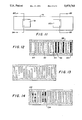
- FIG. 12 is a diagrammatic representation of either the 3/8 ⁇ or 5/8 ⁇ structure of the present invention illustrating typical withdrawal weighting techniques
- FIG. 13 is a diagrammatic representation of either the 3/8 ⁇ or 5/8 ⁇ structure of the present invention illustrating typical overlap weighting techniques
- FIG. 14 is a diagrammatic representation of either the 3/8 ⁇ or 5/8 ⁇ structure of the present invention illustrating typical analogue weighting techniques with additional metal to obtain a desired reflectivity characteristic.
- the first level of the novel GSPUDT transducer configuration with a 3/8 ⁇ periodicity is shown in FIG. 1A.
- the first level of a corresponding transducer with 5/8 ⁇ periodicity is shown in FIG. 2A.
- Both of the single level configurations have no net distributed internal reflections at the design frequency.
- the lowest Fourier component of the surface potential on the electrodes is shown superimposed in dotted lines 11 in both figures.
- FIGS. 1A, 1B and 1C the 3/8ths periodicity or sampling does not change and a 3 ⁇ group repetition rate is maintained.
- the electrodes are 1/4 ⁇ in width while the gaps are 1/8 ⁇ in width.
- FIG. 1A the electrodes are 1/4 ⁇ in width while the gaps are 1/8 ⁇ in width.
- the electrodes have a ⁇ /8 width and the gaps have a ⁇ /4 width.
- the electrodes have a 3/16 ⁇ width and the gaps have a 3/16 ⁇ width.
- the desired advantages are obtained and are accompanied with only a change in the magnitude of coupling and reflectivity.
- FIG. 2A where the electrode widths in each case can be 3/8 ⁇ , 5/16 ⁇ or 1/4 ⁇ and the corresponding gap widths are ⁇ /4, 5/16 ⁇ and 3/8 ⁇ , respectively.
- the transducer 10 has conductive pads 12 and 14 from which extend electrodes in an interdigitated fashion. It will also be noted in both FIG. 1A that a plurality of first pairs of interdigitated electrodes 16, 18, 20 and 22 extend from conductive pads 12 and 14 such that each pair of electrodes 16, 18, 20 and 22 have reversed polarity from the preceding first pair. Thus, it will be noticed that in electrode pair 16, the first electrode 24 extends from transducer pad 14, while the second electrode 26 extends from transducer pad 12. Note the next first pair 18 has the first electrode 28 extending from transducer pad 12 instead of 14 and the second electrode 30 extends from transducer pad 14 instead of transducer pad 12.
- each first pair of the electrodes 16, 18, 20 and 22 has reversed polarity from the preceding first pair.
- a plurality of second pairs of electrodes 32, 34, 36 and 38 are interdigitated with the plurality of first pairs of electrodes 16, 18, 20 and 22.
- both electrodes in each of the second pairs of electrodes 32, 34, 36 and 38 have a common polarity which is opposite the polarity of the adjacent electrodes of a first pair.
- electrodes 40 and 42 forming pair 32 are both coupled to transducer pad 14 while the adjacent first pair electrodes 26 and 28 are both coupled to transducer pad 12.
- the electrodes 40 and 42 forming second pair 32 are of a common polarity that is of opposite polarity than the adjacent electrodes 26 and 28.
- second pair of electrodes 34 also have a common but different polarity than the adjacent electrodes in first pairs 18 and 20.
- FIG. 2A a plurality of first pairs of interdigitated electrodes 44, 46 and 48 are shown. Each pair of those electrodes have a reversed polarity from the preceding pair.
- electrode 50 extends from pad 52 while electrode 54 extends from transducer pad 56.
- the next of the first pairs of interdigitated electrodes 46 has the first electrode 58 extending from transducer conductive pad 56, instead of 52, and the second electrode 60 of pair 46 extends from conductive pad 52 instead of 56.
- An examination will show that all of the electrodes of the first pairs 44, 46 and 48 follows the same pattern.
- a plurality of second pairs of electrodes 62 and 64 are interdigitated with the plurality of first pairs of electrodes 44, 46 and 48 as shown. Both electrodes in each of the second pairs 62 and 64 have a common polarity opposite the polarity of the adjacent first pairs of electrodes, as can be seen. Again in FIG. 2A the pattern repeats in five wavelengths. Further, each of the adjacent electrodes have a center-to-center separation of 5/8 ⁇ . However, the width of the electrodes and gaps may vary as shown without changing the 5/8 ⁇ periodicity.
- the transducer 10 in FIG. 2A has been conveniently shown in three sections 66, 68 and 70.
- the physical width of the electrodes and gaps in each section vary in the drawings but a transducer can be constructed with the same 5/8 ⁇ periodicity but have one of a number of electrode widths and gap widths.
- electrodes are represented to be 3/8 ⁇ in width with the gaps ⁇ /4 in width.
- the electrodes are represented to be 5/16 ⁇ in width and the gaps also have 5/16 ⁇ width.
- the electrodes are represented to have a width of 1/4 ⁇ and the gaps a width of 3/8 ⁇ .
- the three sections 66, 68 and 70 are shown in FIG. 2A merely for illustration.
- FIG. 2B, FIG. 2C, FIG. 2D and FIG. 2E illustrate how the second level of the 5/8 ⁇ transducer can be mass loaded or weighted to obtain unidirectional transmission in either forward or reverse directions on either a CSPUDT or NSPUDT crystal orientation.
- both of the single level configurations illustrated in FIGS. 1A and 2A have no net distributed internal reflections.
- a metalization of fifty percent (50%) would be employed.
- the electrodes and gaps would both have the width of 3/16 ⁇
- both the electrodes and the gaps would have the width of 5/16 ⁇ .
- FIG. 2A is extremely useful in implementing high frequency reflectionless transducers since it has a larger minimum geometry than a two-group "Hopscotch” and has essentially a similar coupling strength. Compare FIGS. 5 and 9 in which FIG. 5 is the absolute magnitude of the coupling of the two-group "Hopscotch” and FIG. 9 is the absolute magnitude of the coupling of the 5/8 ⁇ two-level GSPUDT. Because the minimum geometry for the "Hopscotch" is 1/4 ⁇ , the new 5/8 ⁇ sample structure shown in FIG. 2A can be built at frequencies much higher. Thus, the 5/8 ⁇ sample structure is a significant advance in SAW technology for realizing high frequency reflectionless transducers.
- FIG. 3 illustrates the coupling of a prior art two-electrode per wavelength transducer. It shows a normalized absolute magnitude of approximately 1.3.
- FIG. 7 illustrates the coupling of the 3/8 ⁇ GSPUDT disclosed herein. It shows a normalized absolute magnitude of 1.0, almost as good as the coupling of the prior art two-electrode per wavelength transducer.
- FIG. 4 shows the absolute normalized value of the reflectivity of the prior art two-electrode per wavelength transducer to be approximately 1.5 while FIG. 8 shows the absolute normalized value of the reflectivity of the novel 3/8 ⁇ GSPUDT to be approximately 0.75.
- the 3/8 ⁇ GSPUDT shows excellent coupling and good reflectivity although not as good as the NSPUDT two-electrode per wavelength transducer.
- FIG. 7 also shows a group-type response 70% below the passband with small coupling so it is essentially negligible.
- the 3/8 ⁇ GSPUDT will function well in other applications including filter applications using other 3/8 ⁇ GSPUDT transducers as well as other transducers including an NSPUDT two-electrode per wave length transducer.
- the 3/8 ⁇ GSPUDT transducer When the novel 3/8 ⁇ GSPUDT transducer is compared with the two-electrode per wavelength "Hopscotch” transducer, the 3/8 ⁇ GSPUDT is much superior.
- the coupling of the "Hopscotch” is shown in the normalized graph of FIG. 5 and is shown to be approximately 0.52.
- the coupling of the 3/8 ⁇ GSPUDT is shown in the normalized graph of FIG. 7 to be approximately 1.0 or approximately twice as strong as the "Hopscotch” transducer.
- the "Hopscotch” generates undesirable multiple group type responses that have couplings that are substantially equal to the magnitude of the coupling in the passband.
- the 3/8 ⁇ GSPUDT as shown in FIG. 7, generates only one group type response below the passband that is removed 70% and has only approximately 0.16 coupling magnitude. It is of little consequence.
- the strong group type response 70% above the passband can easily be accommodated with proper matching networks.
- the electrode placement must be such that reflections can be introduced either "in phase” with the imposed potential or displaced by ⁇ /8. This is achieved by the new configurations shown in FIGS. 1A and 2A.
- the structures are bi-directional with single level electrodes as shown in FIGS. 1A and 2A.
- FIGS. 1D and 1E two level versions of the 3/8 ⁇ sample transducer structure are shown that will exhibit unidirectional characteristics on conventional crystal orientations.
- FIGS. 1F and 1G two level versions of the 3/8 ⁇ group sample transducer structure are shown that will exhibit unidirectional characteristics on NSPUDT orientations.
- the sense of directivity is reversed simply by changing the second level metalization.
- FIG. 1D by mass loading only one electrode 40 of each of the second pair of electrodes 32, 34, 36 and 38 and its adjacent electrode 26 (all of the adjacent electrodes in FIG. 1D have been numbered 26), unidirectional transmission can be obtained in one direction in the substrate.
- the transducer is a single level reflectionless conventional transducer that radiates in both directions.
- it When it is mass loaded as illustrated in FIG. 1D on conventional crystal orientations, it becomes unidirectional in one direction.
- FIG. 1E When mass loaded as illustrated in FIG. 1E on a conventional crystal orientation, it becomes unidirectional in the other direction.
- FIG. 1F When mass loaded as illustrated in FIG. 1F, it becomes unidirectional on an NSPUDT configuration in one direction.
- FIG. 1G it becomes unidirectional in the opposite direction on an NSPUDT configuration.
- the same mass loading of FIGS. 1D, 1E, 1F and 1G can, of course, be applied to FIGS. 1B and 1C.
- the only group response is shown at approximately 30% of center frequency which is well below the passband and it has a very low absolute magnitude of approximately 0.18. Thus, it occurs at approximately 70% down in frequency and with a very small amplitude.
- the group response at approximately 70% above center frequency can be removed by a matching network. It can give rise to bulkwave responses that are even further removed from center frequency and thus are not detrimental.
- the reflectivity of the 3/8 ⁇ two-level GSPUDT shown in FIG. 8 can be compared to the reflectivity of a two-electrode/wavelength transducer in FIG. 4 and with the two-group " Hopscotch" reflectivity in FIG. 6.
- the 5/8 ⁇ two-level GSPUDT transducer can be used.
- the difference is in the width of the electrodes which allows the 5/8 ⁇ structure to be used at higher frequencies.
- the coupling of the 5/8 ⁇ two-level GSPUDT is considerably lower than the 3/8 ⁇ two-level GSPUDT.
- the 5/8 ⁇ structure is best used only at high frequencies where the 3/8 ⁇ structure cannot be used.
- the electrodes of the 5/8 ⁇ two-level GSPUDT are 5/16 ⁇ and the gaps are also 5/16 ⁇ .
- the 5/8 ⁇ two-level GSPUDT structure has group responses similar to the "Hopscotch".
- the group response at approximately 60% of the center frequency is identical in amplitude to the center frequency and is substantially identical to the "Hopscotch” group response shown in FIG. 5 except with a little higher coupling.
- the minimum geometry for the "Hopscotch” structure is 1/4 ⁇ , the 5/8 ⁇ two-level GSPUDT structure can be built at frequencies 25% higher than the "Hopscotch".
- FIG. 11 discloses a generalized surface acoustic wave device for forming filters, resonators and the like.
- the piezoelectric crystal substrate 76 has a first transducer 78 and a second transducer 80 in spaced alignment thereon. Input signals may be introduced into the device at terminals 82 and 84 and output signals may be taken from terminals 86 and 88.
- transducers 78 and 80 can be the 3/8 ⁇ GSPUDT structure, or the 5/8 ⁇ GSPUDT structure.
- Either a 3/8 ⁇ or 5/8 ⁇ GSPUDT transducer on an NSPUDT crystal orientation, with appropriately weighted electrodes, could be made to radiate unidirectionally towards the other transducer.
- filters, resonators and like devices can be constructed in the manner generally illustrated with the structures in FIG. 11.
- either of the novel 3/8 ⁇ or 5/8 ⁇ GSPUDTs may be selectively weighted as desired by means well known in the art to give a desired transduction or reflection characteristic.
- certain electrodes may be completely removed such as electrodes 90 and 92 shown in dashed lines to achieve a desired transduction.
- the 3/8 ⁇ or 5/8 ⁇ grid spacing for the structure is not changed.
- Other electrodes may be kept on the same grid spacing but connected to neither conductive pad 98 or 100 to maintain constant velocity but are otherwise withdrawn.
- Such electrodes shown for example only, as electrodes 94 and 96 in FIG. 12.
- Withdrawal weighting of the second level as indicated for example only, may be used to achieve desired reflection characteristics.
- Withdrawal weighting of any form of either or both levels may be used as indicated so long as the electrodes lie on the 3/8 ⁇ or 5/8 ⁇ grid and adjacent electrodes have the 3/8 ⁇ or 5/8 ⁇ spacing.
- FIG. 13 illustrates, for example, how overlap weighting techniques, will known in the art, can be utilized with the novel 3/8 ⁇ and 5/8 ⁇ GSPUDT transducers to obtain a desired transduction characteristic.
Landscapes
- Physics & Mathematics (AREA)
- Acoustics & Sound (AREA)
- Surface Acoustic Wave Elements And Circuit Networks Thereof (AREA)
Priority Applications (6)
| Application Number | Priority Date | Filing Date | Title |
|---|---|---|---|
| US07/608,354 US5073763A (en) | 1990-11-02 | 1990-11-02 | Group single-phase unidirectional transducers with 3/8λand 5/8λ sampling |
| CA002034397A CA2034397C (fr) | 1990-11-02 | 1991-01-17 | Transducteurs unidirectionnels monophases a echantillonnages 3/8 lambda et 5/8 lambda |
| EP91300585A EP0483940B1 (fr) | 1990-11-02 | 1991-01-25 | Transducteurs du type groupe unidirectionnels à phase unique à prises 3/8 lambda et 5/8 lambda |
| DE69120372T DE69120372T2 (de) | 1990-11-02 | 1991-01-25 | Einphasiger, einseitig gerichteter, gruppenförmig angeordneter Wandler mit 3/8 Lambda und 5/8 Lambda Bemusterung |
| FI914778A FI914778L (fi) | 1990-11-02 | 1991-10-10 | Gruppartade enfasiga enkelriktade givare med 3/8n och 5/8n sampling. |
| JP3302765A JPH05267974A (ja) | 1990-11-02 | 1991-10-23 | 3/8λおよび5/8λのサンプリングによるグループの単相の単一方向性トランスジューサ |
Applications Claiming Priority (1)
| Application Number | Priority Date | Filing Date | Title |
|---|---|---|---|
| US07/608,354 US5073763A (en) | 1990-11-02 | 1990-11-02 | Group single-phase unidirectional transducers with 3/8λand 5/8λ sampling |
Publications (1)
| Publication Number | Publication Date |
|---|---|
| US5073763A true US5073763A (en) | 1991-12-17 |
Family
ID=24436113
Family Applications (1)
| Application Number | Title | Priority Date | Filing Date |
|---|---|---|---|
| US07/608,354 Expired - Lifetime US5073763A (en) | 1990-11-02 | 1990-11-02 | Group single-phase unidirectional transducers with 3/8λand 5/8λ sampling |
Country Status (6)
| Country | Link |
|---|---|
| US (1) | US5073763A (fr) |
| EP (1) | EP0483940B1 (fr) |
| JP (1) | JPH05267974A (fr) |
| CA (1) | CA2034397C (fr) |
| DE (1) | DE69120372T2 (fr) |
| FI (1) | FI914778L (fr) |
Cited By (19)
| Publication number | Priority date | Publication date | Assignee | Title |
|---|---|---|---|---|
| US5319326A (en) * | 1991-04-11 | 1994-06-07 | Siemens Matsushita Comp. Gmbh & Co Kg | Surface-wave-type reflective delay line |
| US5406159A (en) * | 1993-11-11 | 1995-04-11 | Rf Monolithics, Inc. | Surface acoustic wave gratings having selected reflectivity |
| US5793146A (en) * | 1993-11-12 | 1998-08-11 | Rf Monolithics, Inc. | Surface acoustic wave transducer having selected reflectivity |
| US5838091A (en) * | 1995-04-04 | 1998-11-17 | Murata Manufacturing Co., Ltd. | Surface acoustic wave device including IDT electrode having solid electrode portion and split electrode portion |
| US6147574A (en) * | 1997-11-20 | 2000-11-14 | Murata Manufacturing Co., Ltd. | Unidirectional surface acoustic wave transducer and transversal-type saw filter having the same |
| US6255759B1 (en) * | 1998-05-11 | 2001-07-03 | Tdk Corporation | Surface acoustic wave device and method of designing the same |
| US6373353B1 (en) * | 1995-11-08 | 2002-04-16 | Ngk Insulators, Ltd. | Surface acoustic wave transducer using NSPUDT property substrate and surface acoustic wave filter using the transducer |
| US20020071996A1 (en) * | 2000-08-22 | 2002-06-13 | Oliver Kienzle | Apparatus and method for exposing a radiation sensitive layer by means of charged particles as well as a mask for this purpose |
| US6480076B2 (en) | 2000-12-21 | 2002-11-12 | Trw Inc. | Recessed reflector single phase unidirectional transducer |
| US6664871B2 (en) | 2002-05-16 | 2003-12-16 | Northrop Grumman Corporation | Cascaded surface acoustic wave filter system for cancelling time spurious responses |
| US6885491B2 (en) | 2001-03-21 | 2005-04-26 | Carl-Zeiss-Stiftung (Trading As Carl Zeiss) | Diffraction-optical component, illumination system and exposure system comprising such a diffraction-optical component as well as an exposure method employing such an exposure system |
| US7002281B2 (en) | 2003-07-16 | 2006-02-21 | Biode Inc. | Multi-reflective acoustic wave device |
| US20080278031A1 (en) * | 2005-09-23 | 2008-11-13 | Andreas Bergmann | Transducer Working With Surface Waves |
| US7692515B2 (en) | 2004-08-04 | 2010-04-06 | Epcos Ag | Low-loss electro-acoustic component |
| US8436509B1 (en) * | 2008-07-08 | 2013-05-07 | Saudia Corporation | High-frequency shear-horizontal surface acoustic wave sensor |
| US9484471B2 (en) * | 2014-09-12 | 2016-11-01 | Qorvo Us, Inc. | Compound varactor |
| US10009002B1 (en) | 2015-09-04 | 2018-06-26 | National Technology & Engineering Solutions Of Sandia, Llc | Methods for suppressing spurious modes in microresonators |
| US10261078B2 (en) | 2015-08-17 | 2019-04-16 | National Technology & Engineering Solutions Of Sandia, Llc | Shear horizontal surface acoustic wave (SH-SAW) resonators and arrays thereof |
| US11405014B1 (en) | 2019-06-27 | 2022-08-02 | National Technology & Engineering Solutions Of Sandia, Llc | Solid-state tuning behavior in acoustic resonators |
Families Citing this family (2)
| Publication number | Priority date | Publication date | Assignee | Title |
|---|---|---|---|---|
| US6534896B2 (en) | 2001-05-15 | 2003-03-18 | Nortel Networks Limited | Spatial harmonic transducers for surface wave devices |
| JP6632481B2 (ja) * | 2016-06-22 | 2020-01-22 | 太陽誘電株式会社 | 弾性波共振器、フィルタおよびマルチプレクサ |
Citations (11)
| Publication number | Priority date | Publication date | Assignee | Title |
|---|---|---|---|---|
| US3792381A (en) * | 1973-02-20 | 1974-02-12 | Hughes Aircraft Co | Surface-wave electro-acoustic transducer |
| US3946342A (en) * | 1973-08-10 | 1976-03-23 | Texas Instruments Incorporated | Weighting surface wave filters by withdrawing electrodes |
| US3979702A (en) * | 1974-04-08 | 1976-09-07 | The Magnavox Company | Apparatus and method for oversampled transducers in acoustic surface wave devices |
| US4353046A (en) * | 1980-11-04 | 1982-10-05 | R F Monolithics, Inc. | Surface acoustic wave device with reflectors |
| JPS60145716A (ja) * | 1984-01-09 | 1985-08-01 | Toshiba Corp | 弾性表面波装置 |
| JPS639216A (ja) * | 1986-06-30 | 1988-01-14 | Nec Corp | 一方向性弾性表面波フイルタ |
| JPS63136706A (ja) * | 1986-11-28 | 1988-06-08 | Toshiba Corp | 弾性表面波トランスジユ−サ |
| JPS63255263A (ja) * | 1987-04-14 | 1988-10-21 | Mitsui Toatsu Chem Inc | ビスマレイミドおよびその製造方法 |
| US4866325A (en) * | 1983-12-28 | 1989-09-12 | Kabushiki Kaisha Toshiba | Surface acoustic wave transducer |
| US4902925A (en) * | 1982-07-29 | 1990-02-20 | R.F. Monolithics, Inc. | Reflectionless transducer |
| US4910839A (en) * | 1984-12-03 | 1990-03-27 | R.F. Monolithics, Inc. | Method of making a single phase unidirectional surface acoustic wave transducer |
Family Cites Families (2)
| Publication number | Priority date | Publication date | Assignee | Title |
|---|---|---|---|---|
| JPS60208110A (ja) * | 1984-03-30 | 1985-10-19 | Kazuhiko Yamanouchi | 反射器内蔵型一方向性弾性表面波変換器 |
| DE3750940T2 (de) * | 1986-07-29 | 1995-05-11 | Rf Monolithics | Wandler. |
-
1990
- 1990-11-02 US US07/608,354 patent/US5073763A/en not_active Expired - Lifetime
-
1991
- 1991-01-17 CA CA002034397A patent/CA2034397C/fr not_active Expired - Fee Related
- 1991-01-25 EP EP91300585A patent/EP0483940B1/fr not_active Expired - Lifetime
- 1991-01-25 DE DE69120372T patent/DE69120372T2/de not_active Expired - Fee Related
- 1991-10-10 FI FI914778A patent/FI914778L/fi unknown
- 1991-10-23 JP JP3302765A patent/JPH05267974A/ja active Pending
Patent Citations (11)
| Publication number | Priority date | Publication date | Assignee | Title |
|---|---|---|---|---|
| US3792381A (en) * | 1973-02-20 | 1974-02-12 | Hughes Aircraft Co | Surface-wave electro-acoustic transducer |
| US3946342A (en) * | 1973-08-10 | 1976-03-23 | Texas Instruments Incorporated | Weighting surface wave filters by withdrawing electrodes |
| US3979702A (en) * | 1974-04-08 | 1976-09-07 | The Magnavox Company | Apparatus and method for oversampled transducers in acoustic surface wave devices |
| US4353046A (en) * | 1980-11-04 | 1982-10-05 | R F Monolithics, Inc. | Surface acoustic wave device with reflectors |
| US4902925A (en) * | 1982-07-29 | 1990-02-20 | R.F. Monolithics, Inc. | Reflectionless transducer |
| US4866325A (en) * | 1983-12-28 | 1989-09-12 | Kabushiki Kaisha Toshiba | Surface acoustic wave transducer |
| JPS60145716A (ja) * | 1984-01-09 | 1985-08-01 | Toshiba Corp | 弾性表面波装置 |
| US4910839A (en) * | 1984-12-03 | 1990-03-27 | R.F. Monolithics, Inc. | Method of making a single phase unidirectional surface acoustic wave transducer |
| JPS639216A (ja) * | 1986-06-30 | 1988-01-14 | Nec Corp | 一方向性弾性表面波フイルタ |
| JPS63136706A (ja) * | 1986-11-28 | 1988-06-08 | Toshiba Corp | 弾性表面波トランスジユ−サ |
| JPS63255263A (ja) * | 1987-04-14 | 1988-10-21 | Mitsui Toatsu Chem Inc | ビスマレイミドおよびその製造方法 |
Cited By (23)
| Publication number | Priority date | Publication date | Assignee | Title |
|---|---|---|---|---|
| US5319326A (en) * | 1991-04-11 | 1994-06-07 | Siemens Matsushita Comp. Gmbh & Co Kg | Surface-wave-type reflective delay line |
| US5406159A (en) * | 1993-11-11 | 1995-04-11 | Rf Monolithics, Inc. | Surface acoustic wave gratings having selected reflectivity |
| US5793146A (en) * | 1993-11-12 | 1998-08-11 | Rf Monolithics, Inc. | Surface acoustic wave transducer having selected reflectivity |
| US5838091A (en) * | 1995-04-04 | 1998-11-17 | Murata Manufacturing Co., Ltd. | Surface acoustic wave device including IDT electrode having solid electrode portion and split electrode portion |
| US6373353B1 (en) * | 1995-11-08 | 2002-04-16 | Ngk Insulators, Ltd. | Surface acoustic wave transducer using NSPUDT property substrate and surface acoustic wave filter using the transducer |
| US6147574A (en) * | 1997-11-20 | 2000-11-14 | Murata Manufacturing Co., Ltd. | Unidirectional surface acoustic wave transducer and transversal-type saw filter having the same |
| US6255759B1 (en) * | 1998-05-11 | 2001-07-03 | Tdk Corporation | Surface acoustic wave device and method of designing the same |
| US20020071996A1 (en) * | 2000-08-22 | 2002-06-13 | Oliver Kienzle | Apparatus and method for exposing a radiation sensitive layer by means of charged particles as well as a mask for this purpose |
| US7015487B2 (en) | 2000-08-22 | 2006-03-21 | Carl Zeiss Smt Ag | Apparatus and method for exposing a radiation sensitive layer by means of charged particles as well as a mask for this purpose |
| US6480076B2 (en) | 2000-12-21 | 2002-11-12 | Trw Inc. | Recessed reflector single phase unidirectional transducer |
| US6885491B2 (en) | 2001-03-21 | 2005-04-26 | Carl-Zeiss-Stiftung (Trading As Carl Zeiss) | Diffraction-optical component, illumination system and exposure system comprising such a diffraction-optical component as well as an exposure method employing such an exposure system |
| US6664871B2 (en) | 2002-05-16 | 2003-12-16 | Northrop Grumman Corporation | Cascaded surface acoustic wave filter system for cancelling time spurious responses |
| US7002281B2 (en) | 2003-07-16 | 2006-02-21 | Biode Inc. | Multi-reflective acoustic wave device |
| US7692515B2 (en) | 2004-08-04 | 2010-04-06 | Epcos Ag | Low-loss electro-acoustic component |
| DE102004037819B4 (de) | 2004-08-04 | 2021-12-16 | Snaptrack, Inc. | Elektroakustisches Bauelement mit geringen Verlusten |
| US20080278031A1 (en) * | 2005-09-23 | 2008-11-13 | Andreas Bergmann | Transducer Working With Surface Waves |
| US7863800B2 (en) * | 2005-09-23 | 2011-01-04 | Epcos Ag | Transducer operating with surface acoustic waves and having four excitation centers |
| US8436509B1 (en) * | 2008-07-08 | 2013-05-07 | Saudia Corporation | High-frequency shear-horizontal surface acoustic wave sensor |
| US8669688B1 (en) * | 2008-07-08 | 2014-03-11 | Sandia Corporation | High-frequency shear-horizontal surface acoustic wave sensor |
| US9484471B2 (en) * | 2014-09-12 | 2016-11-01 | Qorvo Us, Inc. | Compound varactor |
| US10261078B2 (en) | 2015-08-17 | 2019-04-16 | National Technology & Engineering Solutions Of Sandia, Llc | Shear horizontal surface acoustic wave (SH-SAW) resonators and arrays thereof |
| US10009002B1 (en) | 2015-09-04 | 2018-06-26 | National Technology & Engineering Solutions Of Sandia, Llc | Methods for suppressing spurious modes in microresonators |
| US11405014B1 (en) | 2019-06-27 | 2022-08-02 | National Technology & Engineering Solutions Of Sandia, Llc | Solid-state tuning behavior in acoustic resonators |
Also Published As
| Publication number | Publication date |
|---|---|
| EP0483940B1 (fr) | 1996-06-19 |
| EP0483940A1 (fr) | 1992-05-06 |
| DE69120372T2 (de) | 1996-11-14 |
| FI914778A7 (fi) | 1992-05-03 |
| CA2034397C (fr) | 1995-12-12 |
| JPH05267974A (ja) | 1993-10-15 |
| FI914778A0 (fi) | 1991-10-10 |
| DE69120372D1 (de) | 1996-07-25 |
| CA2034397A1 (fr) | 1992-05-03 |
| FI914778L (fi) | 1992-05-03 |
Similar Documents
| Publication | Publication Date | Title |
|---|---|---|
| US5073763A (en) | Group single-phase unidirectional transducers with 3/8λand 5/8λ sampling | |
| EP0184508B1 (fr) | Transducteur à ondes acoustiques de surface | |
| US4353046A (en) | Surface acoustic wave device with reflectors | |
| US3961293A (en) | Multi-resonant surface wave resonator | |
| US3886504A (en) | Acoustic surface wave resonator devices | |
| US3970970A (en) | Multiple acoustically coupled surface acoustic wave resonators | |
| JP3606944B2 (ja) | Sawフィルタ | |
| US4144507A (en) | Surface acoustic wave resonator incorporating coupling transducer into reflecting arrays | |
| US4616197A (en) | Resonator | |
| US3686518A (en) | Unidirectional surface wave transducers | |
| US5093638A (en) | Unbalanced saw filter | |
| US5793146A (en) | Surface acoustic wave transducer having selected reflectivity | |
| US4028648A (en) | Tunable surface wave device resonator | |
| US5621364A (en) | Weighted reflector for surface acoustic waves | |
| US5406159A (en) | Surface acoustic wave gratings having selected reflectivity | |
| US4902925A (en) | Reflectionless transducer | |
| EP0961405A2 (fr) | Dispositif à ondes acoustiques de surface | |
| US5306978A (en) | Surface acoustic wave unidirectional transducer having floating electrodes | |
| US4575696A (en) | Method for using interdigital surface wave transducer to generate unidirectionally propagating surface wave | |
| US4263571A (en) | Surface acoustic wave filter | |
| US3870975A (en) | Surface wave transducer with reduced reflection coefficient | |
| US5818310A (en) | Series-block and line-width weighted saw filter device | |
| US6242844B1 (en) | Wide-band single-phase unidirectional transducer | |
| EP0255263B1 (fr) | Transducteur | |
| US4365220A (en) | Surface wave circuit device |
Legal Events
| Date | Code | Title | Description |
|---|---|---|---|
| AS | Assignment |
Owner name: R. F. MONOLITHICS, INC., 4441 SIGMA RD., DALLAS, T Free format text: ASSIGNMENT OF ASSIGNORS INTEREST.;ASSIGNOR:WRIGHT, PETER;REEL/FRAME:005499/0509 Effective date: 19901031 |
|
| STCF | Information on status: patent grant |
Free format text: PATENTED CASE |
|
| FEPP | Fee payment procedure |
Free format text: PAYOR NUMBER ASSIGNED (ORIGINAL EVENT CODE: ASPN); ENTITY STATUS OF PATENT OWNER: SMALL ENTITY |
|
| FPAY | Fee payment |
Year of fee payment: 4 |
|
| FEPP | Fee payment procedure |
Free format text: PAT HLDR NO LONGER CLAIMS SMALL ENT STAT AS SMALL BUSINESS (ORIGINAL EVENT CODE: LSM2); ENTITY STATUS OF PATENT OWNER: SMALL ENTITY |
|
| FPAY | Fee payment |
Year of fee payment: 8 |
|
| AS | Assignment |
Owner name: WELLS FARGO BANK MINNESOTA, N.A., MINNESOTA Free format text: SECURITY INTEREST;ASSIGNOR:RF MONOLITHICS, INC.;REEL/FRAME:011533/0104 Effective date: 20001208 |
|
| AS | Assignment |
Owner name: WELLS FARGO BUSINESS CREDIT, INC., TEXAS Free format text: CORRECTION OF SECURED PARTY REEL/FRAME 011533/0104;ASSIGNOR:RF MONOLITHICS, INC.;REEL/FRAME:011944/0153 Effective date: 20001208 Owner name: WELLS FARGO BANK MINNESOTA,N.A., MINNESOTA Free format text: CORRECTION OF SECURED PARTY REEL/FRAME 011533/0104;ASSIGNOR:RF MONOLITHICS, INC.;REEL/FRAME:011944/0153 Effective date: 20001208 |
|
| FEPP | Fee payment procedure |
Free format text: PAT HOLDER CLAIMS SMALL ENTITY STATUS, ENTITY STATUS SET TO SMALL (ORIGINAL EVENT CODE: LTOS); ENTITY STATUS OF PATENT OWNER: SMALL ENTITY |
|
| FPAY | Fee payment |
Year of fee payment: 12 |
|
| REMI | Maintenance fee reminder mailed |