US5076540A - Stop valve - Google Patents
Stop valve Download PDFInfo
- Publication number
- US5076540A US5076540A US07/609,970 US60997090A US5076540A US 5076540 A US5076540 A US 5076540A US 60997090 A US60997090 A US 60997090A US 5076540 A US5076540 A US 5076540A
- Authority
- US
- United States
- Prior art keywords
- valve body
- control sleeve
- valve
- sleeve
- bore
- Prior art date
- Legal status (The legal status is an assumption and is not a legal conclusion. Google has not performed a legal analysis and makes no representation as to the accuracy of the status listed.)
- Expired - Lifetime
Links
- 238000007789 sealing Methods 0.000 claims abstract description 18
- 230000015572 biosynthetic process Effects 0.000 claims abstract description 9
- 238000005755 formation reaction Methods 0.000 claims abstract description 9
- 230000003014 reinforcing effect Effects 0.000 claims abstract description 6
- 239000012530 fluid Substances 0.000 claims description 14
- 238000011144 upstream manufacturing Methods 0.000 claims description 5
- 238000009428 plumbing Methods 0.000 claims description 4
- 230000000295 complement effect Effects 0.000 claims 3
- XLYOFNOQVPJJNP-UHFFFAOYSA-N water Substances O XLYOFNOQVPJJNP-UHFFFAOYSA-N 0.000 description 7
- 238000000926 separation method Methods 0.000 description 6
- 238000006073 displacement reaction Methods 0.000 description 4
- 229910001369 Brass Inorganic materials 0.000 description 1
- 230000002411 adverse Effects 0.000 description 1
- 239000010951 brass Substances 0.000 description 1
- 239000000463 material Substances 0.000 description 1
- 239000004033 plastic Substances 0.000 description 1
- 230000008439 repair process Effects 0.000 description 1
- 229920003031 santoprene Polymers 0.000 description 1
- 239000012815 thermoplastic material Substances 0.000 description 1
Images

Classifications
-
- F—MECHANICAL ENGINEERING; LIGHTING; HEATING; WEAPONS; BLASTING
- F16—ENGINEERING ELEMENTS AND UNITS; GENERAL MEASURES FOR PRODUCING AND MAINTAINING EFFECTIVE FUNCTIONING OF MACHINES OR INSTALLATIONS; THERMAL INSULATION IN GENERAL
- F16K—VALVES; TAPS; COCKS; ACTUATING-FLOATS; DEVICES FOR VENTING OR AERATING
- F16K5/00—Plug valves; Taps or cocks comprising only cut-off apparatus having at least one of the sealing faces shaped as a more or less complete surface of a solid of revolution, the opening and closing movement being predominantly rotary
- F16K5/04—Plug valves; Taps or cocks comprising only cut-off apparatus having at least one of the sealing faces shaped as a more or less complete surface of a solid of revolution, the opening and closing movement being predominantly rotary with plugs having cylindrical surfaces; Packings therefor
- F16K5/0414—Plug channel at 90 degrees to the inlet
-
- Y—GENERAL TAGGING OF NEW TECHNOLOGICAL DEVELOPMENTS; GENERAL TAGGING OF CROSS-SECTIONAL TECHNOLOGIES SPANNING OVER SEVERAL SECTIONS OF THE IPC; TECHNICAL SUBJECTS COVERED BY FORMER USPC CROSS-REFERENCE ART COLLECTIONS [XRACs] AND DIGESTS
- Y10—TECHNICAL SUBJECTS COVERED BY FORMER USPC
- Y10T—TECHNICAL SUBJECTS COVERED BY FORMER US CLASSIFICATION
- Y10T137/00—Fluid handling
- Y10T137/598—With repair, tapping, assembly, or disassembly means
- Y10T137/6031—Assembling or disassembling rotary valve
- Y10T137/6058—Plug valve
-
- Y—GENERAL TAGGING OF NEW TECHNOLOGICAL DEVELOPMENTS; GENERAL TAGGING OF CROSS-SECTIONAL TECHNOLOGIES SPANNING OVER SEVERAL SECTIONS OF THE IPC; TECHNICAL SUBJECTS COVERED BY FORMER USPC CROSS-REFERENCE ART COLLECTIONS [XRACs] AND DIGESTS
- Y10—TECHNICAL SUBJECTS COVERED BY FORMER USPC
- Y10T—TECHNICAL SUBJECTS COVERED BY FORMER US CLASSIFICATION
- Y10T137/00—Fluid handling
- Y10T137/598—With repair, tapping, assembly, or disassembly means
- Y10T137/6031—Assembling or disassembling rotary valve
- Y10T137/6058—Plug valve
- Y10T137/6062—Having retainer at actuator end
-
- Y—GENERAL TAGGING OF NEW TECHNOLOGICAL DEVELOPMENTS; GENERAL TAGGING OF CROSS-SECTIONAL TECHNOLOGIES SPANNING OVER SEVERAL SECTIONS OF THE IPC; TECHNICAL SUBJECTS COVERED BY FORMER USPC CROSS-REFERENCE ART COLLECTIONS [XRACs] AND DIGESTS
- Y10—TECHNICAL SUBJECTS COVERED BY FORMER USPC
- Y10T—TECHNICAL SUBJECTS COVERED BY FORMER US CLASSIFICATION
- Y10T74/00—Machine element or mechanism
- Y10T74/20—Control lever and linkage systems
- Y10T74/20576—Elements
- Y10T74/20732—Handles
- Y10T74/20834—Hand wheels
- Y10T74/2084—Knob or dial
Definitions
- This invention relates to stop valves commonly used in water supply lines leading to sinks, toilets and the like.
- a stop valve is simply a shut-off valve to permit replacement of washers or other repairs to be accomplished on a fixture valve without shutting down an entire plumbing system.
- the stop valve is commonly located in the fixture supply line between the wall and the fixture. Stop valves are generally available in two basic styles. One style is known as an angle stop valve, wherein the inlet and outlet of the valve are at right angles to each other. The other standard configuration is a straight-through arrangement wherein the inlet and outlet are coaxially aligned with each other.
- the present invention is directed to reducing or even eliminating the longitudinal displacement of the control sleeve in the remote possibility of handle separation from the resilient control sleeve.
- the stop valve of the present invention includes just three parts: valve body, resilient control sleeve and handle. No supplementary sealing or securing elements are required.
- the handle is secured to the valve body by formations which resiliently snap into a circumferential ring on the valve body. Cooperating splines provide a driving connection between the handle and control sleeve to cause them to rotate together.
- a tapered collar in the valve body bore engages a tapered shoulder on the sleeve to prevent the sleeve from being blown out of the valve in the event of excessive fluid pressure and failure of the handle-retaining formations, and to prevent downstream axial or longitudinal displacement of said sleeve in the valve body bore in case of separation of the handle from the sleeve.
- the control sleeve has a resilient circumferential sealing flap which is dimensioned to provide an interference fit with the valve body bore, providing an effective seal and frictionally preventing withdrawal of the sleeve.
- the inlet end of the control sleeve has a reduced wall thickness to increase its radial yieldability to provide increased sealing pressure under low fluid pressure conditions.
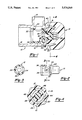
- FIG. 1 is a cross-sectional view of the stop valve assembly of the present invention, shown in the open condition of the valve.
- FIG. 2 is a top view of the control sleeve of FIG. 1.
- FIG. 3 is a cross-sectional view of the control sleeve, viewed in the direction of arrows 3--3 of FIG. 2.
- FIG. 4 is a cross-sectional view of the assembly, viewed in the direction of arrows 4--4 of FIG. 1.
- FIG. 5 is a view similar to FIG. 1, but showing a modified embodiment of the control sleeve.
- FIG. 6 is a view similar to FIG. 3, but showing the modified sleeve of FIG. 5.
- FIG. 7 is an enlarged cross-sectional view of the collar having a tapered rim.
- FIG. 8 is an enlarged view of the indicated portion of FIG. 1.
- FIG. 1 illustrates an angle stop valve of the type wherein a one-quarter turn of the handle is sufficient to change the condition of the valve from the illustrated fully open condition to fully closed.
- the valve generally comprises a valve body 10 which receives a resilient control sleeve 12 which is selectively rotated by a handle 14.
- the valve body 10 includes inlet bore 16 adapted to be connected to a water supply line, outlet bore 18 adapted to be connected to an outlet line and neck 20 which rotatably supports and interconnects with handle 14 in a manner to be described below.
- Resilient control sleeve 12 is rotatably mounted within valve body inlet bore 16 and is inserted from the opening thereof, that is, from the left toward the right as viewed in FIG. 1.
- the cylindrically shaped side wall of control sleeve 12 is provided with a port 24 which may be selectively brought into registry with valve body outlet bore 18 to establish a fluid flow path from inlet bore 16, through sleeve bore 22 and port 24 and finally out through outlet bore 18.
- control sleeve 12 is of reduced diameter and is provided with longitudinally extending splines 26 which telescopically interfit with internal splines 28 in handle 14. As best shown in FIG. 4, these splines are asymmetrically arranged around the circumference of the control sleeve so that the handle and control sleeve can only be assembled in one relative angular relationship. This feature, when coupled with appropriate positional indicia on the exterior of the handle, permits the operator to determine the on-off condition of the valve.
- Control sleeve 12 is further provided with a radially projecting circumferential sealing lip or flap 34 immediately adjacent to a circumferential groove 35 and abutting valve body collar 32.
- the outer diameter of flap 34 is shaped and dimensioned to be larger than the opposed bore of valve body, so that assembly results in flap 34 being forced radially inwardly and toward the left to establish a continuous radially outward sealing pressure against the valve body bore.
- the diameter of the main body portion of the control sleeve 12 is dimensioned to be very snuggly received within the opposed portion of valve body inlet bore 16, to minimize any potential for water leakage therebetween.
- flap 34 also cause it to increase its frictional engagement with the valve body bore if the sleeve moves toward the left, thereby preventing misalignment of port 24 and bore 18 and preventing removal of the sleeve from the valve body.
- control sleeve 12 has a tapered section 60 adjacent to and upstream of sealing flap 34.
- the tapered section 60 extends around the entire circumference of the closed end of control sleeve 12.
- the taper angle formed with the center axis of the control sleeve is generally from about 6° to about 25°, preferably from about 8° to about 20°, and more preferably from about 10° to about 15°.
- the tapered section 60 forms a taper lock with the tapered collar 32 as more fully described hereinafter to prevent longitudinal downstream movement of the control sleeve in the valve body bore in the unlikely possibility of handle separation from the control sleeve.
- control sleeve 12 As a further aid in preventing leakage between the outer periphery of control sleeve 12 and inlet bore 16, the inlet end of control sleeve 12 is formed with an end lip 36 of reduced wall thickness. Therefore, even under low fluid pressure conditions, the locally weakened portion of the control sleeve 12 will tend to be forced radially outwardly against the valve body bore by the fluid pressure which always exists within the interior bore 22 of the control sleeve.
- control sleeve 12 is further provided with a single longitudinally extending reinforcing rib 38 along its internal bore 22.
- the axial position and length of rib 38 is selected to substantially correspond with the diameter of valve body outlet bore 18, and the angular position of such rib is spaced a quarter turn from control sleeve port 24.
- This arrangement places rib 38 directly across the diameter of valve body outlet bore 18 when the control sleeve is in its closed position.
- the rib locally increases the stiffness of the control sleeve wall and prevents it from bulging radially outwardly into outlet bore 18 under high fluid pressure conditions when the valve is in its closed position. Such bulging would be undesirable because it would tend to produce wear on the exterior surface of the control sleeve as such surface rubbed against the opposed edges of the outlet bore opening when the control sleeve was moved from the closed toward the open position.
- Neck 20 of valve body 10 has a circumferential groove 40 which receives a plurality of circumferentially spaced radially inwardly projecting handle retaining bosses 42.
- handle 14 is constructed so that its outer circumference is radially yieldable as the handle is pressed toward the left over the conically configured tip of valve body neck 20. Continued leftward movement of the handle causes retaining lips 42 to be cammed radially outwardly until they snap resiliently inwardly into neck groove 40. In this manner, handle 14 is rotatably mounted on and connected to valve body 10, without the need for any supplementary fastening devices.
- the extreme right-hand end of neck 40 is recessed for approximately one-half of its circumference, establishing rotation stop faces 44 and 46 where the recessed portion meets the unrecessed portion.
- rotation of handle 14 in the counterclockwise direction (as viewed in FIG. 4) from the position shown causes stop boss 48 to abut stop face 46, thereby establishing the closed position after a little more than 90 degrees of rotation.
- rotation in the clockwise direction from such closed position to the illustrated open position of the valve brings the other end of stop boss 48 into abutting engagement with the other stop face 44, establishing the open position of the valve.
- the angular extent of stop boss 49 is slightly less than 90 degrees in the preferred embodiment of the invention.
- Collar 32 of the valve body serves several functions. First, it establishes the proper axial position of the control sleeve relative to outlet bore 18 by its abutting engagement with the shoulder on control sleeve 12 adjacent sealing flap 34. This engagement assures the proper axial registry of port 24 with outlet bore 18. Second, collar 32 also provides a safety feature in that fluid pressure cannot blow or force control sleeve 12 out to the right or upstream through valve body neck 20 in the event that the interlock between handle 14 and neck groove 40 has been destroyed or the handle has otherwise been removed from the valve body.
- the collar 32 has a tapered inner rim 50.
- the rim is tapered in a downstream direction of the valve body and has a piercing point 51 at its upstream side 52, i.e., the side adjacent the handle 14.
- the taper angle ⁇ formed with the center axis of the valve body, represented by line "a" in FIG. 7, is an angle which is sufficient to form a piercing point 51 effective to pierce the tapered portion 60 of the resilient control sleeve 12. Generally this angle is from about 12° to about 35°, preferably from about 15° to about 30°, and more preferably from about 18° to about 25°.
- the difference between the taper angle of the rim 50 of the collar 32 and the tapered section 60 of the control sleeve i.e., taper angle of rim 50 minus taper angle of tapered portion 60
- the difference between the two taper angles is 0, the piercing point 51 of the rim 50 will not penetrate or extend into the tapered section 60, and the control sleeve will not be locked to the collar against longitudinal or axial downstream displacement in the bore 16.
- the difference between the two angles is greater than zero but less than about 2°, a major portion of the surface of tapered rim 50 will be in surface to surface contact with the surface of tapered portion 60 of the control sleeve. This results in increased torque required to rotate the control sleeve. If, on the other hand, the difference between the two angles exceeds about 35°, too little of the rim 50 is in contact with the tapered section 60 of the control sleeve. Since the interface of rim 50 of the collar 32 and the tapered section 60 of the control sleeve also functions as a secondary seal to prevent water leakage, reducing the interface contact therebetween tends to adversely affect the sealing function.
- a portion of the collar 32 has a larger internal diameter than the outer diameter of the tapered section 60.
- This portion is the upstream portion, i.e., the portion adjacent to and including the piercing point 51.
- the downstream portion of the collar 32 furthest removed from the piercing point 51 has a smaller internal diameter than the outer diameter of the tapered section 60 of the control sleeve.
- the valve body is preferably formed of extruded brass which is subsequently machined.
- the control sleeve is formed of a low friction resilient thermoplastic material, preferably Santoprene 103-40, manufactured by Monsanto.
- the handle can be formed of a durable plastic material such as ABS having a proper degree of resilience to permit its assembly to the valve body in the manner described above.
- an alternative embodiment of the invention may be constructed with the portion of control sleeve 12 to the left of circumferential groove 35 being formed with a conical rather than cylindrical wall. That is, the diameter would be progressively greater toward the open left end of the sleeve.
- FIGS. 5-6 illustrate two additional optional features.
- an additional internal longitudinal rib 50 at the leading edge of port 24 as the valve is turned to the closed position. In this position, such additional rib provides additional rigidity as the pressure within the sleeve builds up, during valve closing, to prevent the sleeve from ballooning or bulging outwardly into the outlet port.
- Another optional feature is the inclusion of a radially inwardly projecting circumferential rib 52 adjacent to end flap 36, which rib provides additional stiffness to the sleeve wall to prevent it from collapsing radially inwardly.
- an O-ring can be provided around the portion of handle 14 which extends inside valve body neck 20, with appropriate O-ring-receiving grooves being provided.
Landscapes
- Engineering & Computer Science (AREA)
- General Engineering & Computer Science (AREA)
- Mechanical Engineering (AREA)
- Taps Or Cocks (AREA)
Priority Applications (2)
| Application Number | Priority Date | Filing Date | Title |
|---|---|---|---|
| US07/609,970 US5076540A (en) | 1990-05-14 | 1990-11-06 | Stop valve |
| CA 2052002 CA2052002C (fr) | 1990-11-06 | 1991-09-23 | Soupape |
Applications Claiming Priority (2)
| Application Number | Priority Date | Filing Date | Title |
|---|---|---|---|
| SE901086 | 1990-05-14 | ||
| US07/609,970 US5076540A (en) | 1990-05-14 | 1990-11-06 | Stop valve |
Publications (1)
| Publication Number | Publication Date |
|---|---|
| US5076540A true US5076540A (en) | 1991-12-31 |
Family
ID=24443087
Family Applications (1)
| Application Number | Title | Priority Date | Filing Date |
|---|---|---|---|
| US07/609,970 Expired - Lifetime US5076540A (en) | 1990-05-14 | 1990-11-06 | Stop valve |
Country Status (2)
| Country | Link |
|---|---|
| US (1) | US5076540A (fr) |
| CA (1) | CA2052002C (fr) |
Cited By (14)
| Publication number | Priority date | Publication date | Assignee | Title |
|---|---|---|---|---|
| US5505197A (en) * | 1992-12-11 | 1996-04-09 | Modex/Metric Products, Inc. | Respirator mask with tapered filter mount and valve aligning pins and ears |
| US5695169A (en) * | 1996-06-28 | 1997-12-09 | Brass-Craft Manufacturing Company | Stop valve with sturdy handle connection |
| WO2000059416A1 (fr) * | 1999-04-06 | 2000-10-12 | Ssl International Plc | Robinet |
| US6497245B1 (en) * | 1999-10-13 | 2002-12-24 | Denso Corporation | Intake air controller for internal combustion engine and manufacturing the same |
| WO2004011829A2 (fr) | 2002-07-31 | 2004-02-05 | Brass-Craft Manufacturing Company | Soupape d'arret |
| US20040089835A1 (en) * | 2002-11-08 | 2004-05-13 | Schreiner Michael R. | Valve with removable actuator |
| US20050109969A1 (en) * | 2003-11-21 | 2005-05-26 | Turnau William F.Iii | Stem construction for rotatable valve body |
| US20060220398A1 (en) * | 2005-03-30 | 2006-10-05 | Talleres De Escoriaza, S.A. | Ergonomic manual actuator for door locks |
| US20100300558A1 (en) * | 2009-03-11 | 2010-12-02 | Victor Equipment Company | Gas Pressure Regulator Having Energy Absorbing Features |
| WO2010143018A1 (fr) * | 2009-06-12 | 2010-12-16 | Christiaan Johannes Meintjes | Robinet |
| US20130015270A1 (en) * | 2011-07-14 | 2013-01-17 | Yuan-Mei Corp. | Finger-operated switch |
| WO2016096496A1 (fr) * | 2014-12-17 | 2016-06-23 | Nestec S.A. | Élément robinet rotatif et distributeur d'aliments comportant cet élément robinet |
| US10443743B2 (en) * | 2017-11-14 | 2019-10-15 | Brasscraft Manufacturing Company | Rotary plug valve |
| US20220146006A1 (en) * | 2019-02-21 | 2022-05-12 | Giacomini S.P.A. | Valve for hydraulic control and balancing of fluid flow rate |
Citations (8)
| Publication number | Priority date | Publication date | Assignee | Title |
|---|---|---|---|---|
| US3481367A (en) * | 1967-06-13 | 1969-12-02 | Brunswick Corp | Three-way stopcock |
| US3503586A (en) * | 1967-06-21 | 1970-03-31 | Applic Gaz Sa | Valves |
| US3783900A (en) * | 1972-06-05 | 1974-01-08 | Medex Inc | Stop cock |
| US3807692A (en) * | 1972-05-01 | 1974-04-30 | Dynatech Corp | Valve, method of manufacture of valve and valve made by such method |
| US4219046A (en) * | 1978-07-17 | 1980-08-26 | The Dow Chemical Company | Plug valve and method |
| US4319735A (en) * | 1980-07-22 | 1982-03-16 | Stanadyne, Inc. | Faucet valves |
| US4562994A (en) * | 1985-03-18 | 1986-01-07 | Brass Craft Manufacturing Company | Valve |
| US4890817A (en) * | 1987-05-15 | 1990-01-02 | Plasson Maagan Michael Industries, Ltd. | Quarter-turn valve |
-
1990
- 1990-11-06 US US07/609,970 patent/US5076540A/en not_active Expired - Lifetime
-
1991
- 1991-09-23 CA CA 2052002 patent/CA2052002C/fr not_active Expired - Fee Related
Patent Citations (9)
| Publication number | Priority date | Publication date | Assignee | Title |
|---|---|---|---|---|
| US3481367A (en) * | 1967-06-13 | 1969-12-02 | Brunswick Corp | Three-way stopcock |
| US3503586A (en) * | 1967-06-21 | 1970-03-31 | Applic Gaz Sa | Valves |
| US3807692A (en) * | 1972-05-01 | 1974-04-30 | Dynatech Corp | Valve, method of manufacture of valve and valve made by such method |
| US3783900A (en) * | 1972-06-05 | 1974-01-08 | Medex Inc | Stop cock |
| US4219046A (en) * | 1978-07-17 | 1980-08-26 | The Dow Chemical Company | Plug valve and method |
| US4319735A (en) * | 1980-07-22 | 1982-03-16 | Stanadyne, Inc. | Faucet valves |
| US4562994A (en) * | 1985-03-18 | 1986-01-07 | Brass Craft Manufacturing Company | Valve |
| US4609177A (en) * | 1985-03-18 | 1986-09-02 | Brasscraft Manufacturing Company | Valve |
| US4890817A (en) * | 1987-05-15 | 1990-01-02 | Plasson Maagan Michael Industries, Ltd. | Quarter-turn valve |
Cited By (22)
| Publication number | Priority date | Publication date | Assignee | Title |
|---|---|---|---|---|
| US5505197A (en) * | 1992-12-11 | 1996-04-09 | Modex/Metric Products, Inc. | Respirator mask with tapered filter mount and valve aligning pins and ears |
| US5695169A (en) * | 1996-06-28 | 1997-12-09 | Brass-Craft Manufacturing Company | Stop valve with sturdy handle connection |
| WO2000059416A1 (fr) * | 1999-04-06 | 2000-10-12 | Ssl International Plc | Robinet |
| US6722624B1 (en) | 1999-04-06 | 2004-04-20 | Coloplast A/S | Tap |
| US6497245B1 (en) * | 1999-10-13 | 2002-12-24 | Denso Corporation | Intake air controller for internal combustion engine and manufacturing the same |
| WO2004011829A2 (fr) | 2002-07-31 | 2004-02-05 | Brass-Craft Manufacturing Company | Soupape d'arret |
| US7048251B2 (en) | 2002-11-08 | 2006-05-23 | Caleffi S.P.A. | Valve with removable actuator |
| US20040089835A1 (en) * | 2002-11-08 | 2004-05-13 | Schreiner Michael R. | Valve with removable actuator |
| US7178786B2 (en) * | 2003-11-21 | 2007-02-20 | Brass-Craft Manufacturing Company | Stem construction for rotatable valve body |
| US20050109969A1 (en) * | 2003-11-21 | 2005-05-26 | Turnau William F.Iii | Stem construction for rotatable valve body |
| US20060220398A1 (en) * | 2005-03-30 | 2006-10-05 | Talleres De Escoriaza, S.A. | Ergonomic manual actuator for door locks |
| US8869822B2 (en) * | 2009-03-11 | 2014-10-28 | Victor Equipment Company | Gas pressure regulator having energy absorbing features |
| US20100300558A1 (en) * | 2009-03-11 | 2010-12-02 | Victor Equipment Company | Gas Pressure Regulator Having Energy Absorbing Features |
| US9109753B2 (en) * | 2009-03-11 | 2015-08-18 | Victor Equipment Company | Gas pressure regulator having energy absorbing features |
| US20150027550A1 (en) * | 2009-03-11 | 2015-01-29 | Victor Equipment Company | Gas Pressure Regulator Having Energy Absorbing Features |
| WO2010143018A1 (fr) * | 2009-06-12 | 2010-12-16 | Christiaan Johannes Meintjes | Robinet |
| US8596558B2 (en) * | 2011-07-14 | 2013-12-03 | Yuan-Mei Corp. | Finger-operated switch |
| US20130015270A1 (en) * | 2011-07-14 | 2013-01-17 | Yuan-Mei Corp. | Finger-operated switch |
| WO2016096496A1 (fr) * | 2014-12-17 | 2016-06-23 | Nestec S.A. | Élément robinet rotatif et distributeur d'aliments comportant cet élément robinet |
| US10443743B2 (en) * | 2017-11-14 | 2019-10-15 | Brasscraft Manufacturing Company | Rotary plug valve |
| US20220146006A1 (en) * | 2019-02-21 | 2022-05-12 | Giacomini S.P.A. | Valve for hydraulic control and balancing of fluid flow rate |
| US11867302B2 (en) * | 2019-02-21 | 2024-01-09 | Giacomini S.P.A. | Valve for hydraulic control and balancing of fluid flow rate |
Also Published As
| Publication number | Publication date |
|---|---|
| CA2052002A1 (fr) | 1992-05-07 |
| CA2052002C (fr) | 1994-09-20 |
Similar Documents
| Publication | Publication Date | Title |
|---|---|---|
| US4609177A (en) | Valve | |
| CA2052002C (fr) | Soupape | |
| US6089540A (en) | Plug-in connection with leakage protection | |
| US5701934A (en) | Rotary diverter valve | |
| US4185781A (en) | Quick-disconnect nozzle connection | |
| US5087086A (en) | Quick connect coupling with pressure relief | |
| US3802457A (en) | Plug valve with combined plug operating, retaining, and removal means | |
| US4899982A (en) | Upper valve component | |
| US5695169A (en) | Stop valve with sturdy handle connection | |
| EP0437317A1 (fr) | Raccord segmentaire pour tuyaux | |
| EP1052439B1 (fr) | Robinet de sécurité pour fluides | |
| SU1808065A3 (en) | Plug safety clutch for pressure pipe lines | |
| US4314581A (en) | Rotary valve washerless cartridge | |
| US4330011A (en) | Faucet valve with early shutoff | |
| JP4101337B2 (ja) | ドリル加工バルブ | |
| US7137762B2 (en) | Device for tapping conduits | |
| US4434809A (en) | Pipe coupling | |
| CA1288756C (fr) | Robinet-vanne | |
| US4848728A (en) | Coupling arrangement | |
| US4621790A (en) | Butterfly valve | |
| US4488741A (en) | Compression coupling for service valve | |
| JP7061527B2 (ja) | 吐水管の回動規制構造 | |
| US5803356A (en) | Thermostat bypass system | |
| JPH0514058Y2 (fr) | ||
| US5118073A (en) | Valve |
Legal Events
| Date | Code | Title | Description |
|---|---|---|---|
| AS | Assignment |
Owner name: BRASS-CRAFT MANUFACTURING COMPANY A MI CORPORATI Free format text: ASSIGNMENT OF ASSIGNORS INTEREST.;ASSIGNOR:MURPHY, ROGER W.;REEL/FRAME:005863/0359 Effective date: 19901106 |
|
| STCF | Information on status: patent grant |
Free format text: PATENTED CASE |
|
| FPAY | Fee payment |
Year of fee payment: 4 |
|
| CC | Certificate of correction | ||
| FPAY | Fee payment |
Year of fee payment: 8 |
|
| FPAY | Fee payment |
Year of fee payment: 12 |