US5122032A - Disposable pump assembly - Google Patents
Disposable pump assembly Download PDFInfo
- Publication number
- US5122032A US5122032A US07/725,921 US72592191A US5122032A US 5122032 A US5122032 A US 5122032A US 72592191 A US72592191 A US 72592191A US 5122032 A US5122032 A US 5122032A
- Authority
- US
- United States
- Prior art keywords
- pump body
- volute
- impeller
- riser
- riser portion
- Prior art date
- Legal status (The legal status is an assumption and is not a legal conclusion. Google has not performed a legal analysis and makes no representation as to the accuracy of the status listed.)
- Expired - Lifetime
Links
Images


Classifications
-
- F—MECHANICAL ENGINEERING; LIGHTING; HEATING; WEAPONS; BLASTING
- F04—POSITIVE - DISPLACEMENT MACHINES FOR LIQUIDS; PUMPS FOR LIQUIDS OR ELASTIC FLUIDS
- F04D—NON-POSITIVE-DISPLACEMENT PUMPS
- F04D7/00—Pumps adapted for handling specific fluids, e.g. by selection of specific materials for pumps or pump parts
- F04D7/02—Pumps adapted for handling specific fluids, e.g. by selection of specific materials for pumps or pump parts of centrifugal type
-
- B—PERFORMING OPERATIONS; TRANSPORTING
- B41—PRINTING; LINING MACHINES; TYPEWRITERS; STAMPS
- B41F—PRINTING MACHINES OR PRESSES
- B41F31/00—Inking arrangements or devices
- B41F31/02—Ducts, containers, supply or metering devices
- B41F31/08—Ducts, containers, supply or metering devices with ink ejecting means, e.g. pumps, nozzles
-
- F—MECHANICAL ENGINEERING; LIGHTING; HEATING; WEAPONS; BLASTING
- F04—POSITIVE - DISPLACEMENT MACHINES FOR LIQUIDS; PUMPS FOR LIQUIDS OR ELASTIC FLUIDS
- F04D—NON-POSITIVE-DISPLACEMENT PUMPS
- F04D13/00—Pumping installations or systems
- F04D13/02—Units comprising pumps and their driving means
- F04D13/06—Units comprising pumps and their driving means the pump being electrically driven
- F04D13/08—Units comprising pumps and their driving means the pump being electrically driven for submerged use
-
- F—MECHANICAL ENGINEERING; LIGHTING; HEATING; WEAPONS; BLASTING
- F04—POSITIVE - DISPLACEMENT MACHINES FOR LIQUIDS; PUMPS FOR LIQUIDS OR ELASTIC FLUIDS
- F04D—NON-POSITIVE-DISPLACEMENT PUMPS
- F04D29/00—Details, component parts, or accessories
- F04D29/02—Selection of particular materials
- F04D29/026—Selection of particular materials especially adapted for liquid pumps
-
- F—MECHANICAL ENGINEERING; LIGHTING; HEATING; WEAPONS; BLASTING
- F04—POSITIVE - DISPLACEMENT MACHINES FOR LIQUIDS; PUMPS FOR LIQUIDS OR ELASTIC FLUIDS
- F04D—NON-POSITIVE-DISPLACEMENT PUMPS
- F04D29/00—Details, component parts, or accessories
- F04D29/18—Rotors
- F04D29/20—Mounting rotors on shafts
-
- F—MECHANICAL ENGINEERING; LIGHTING; HEATING; WEAPONS; BLASTING
- F04—POSITIVE - DISPLACEMENT MACHINES FOR LIQUIDS; PUMPS FOR LIQUIDS OR ELASTIC FLUIDS
- F04D—NON-POSITIVE-DISPLACEMENT PUMPS
- F04D29/00—Details, component parts, or accessories
- F04D29/18—Rotors
- F04D29/22—Rotors specially for centrifugal pumps
- F04D29/2238—Special flow patterns
-
- F—MECHANICAL ENGINEERING; LIGHTING; HEATING; WEAPONS; BLASTING
- F04—POSITIVE - DISPLACEMENT MACHINES FOR LIQUIDS; PUMPS FOR LIQUIDS OR ELASTIC FLUIDS
- F04D—NON-POSITIVE-DISPLACEMENT PUMPS
- F04D29/00—Details, component parts, or accessories
- F04D29/40—Casings; Connections of working fluid
- F04D29/42—Casings; Connections of working fluid for radial or helico-centrifugal pumps
- F04D29/426—Casings; Connections of working fluid for radial or helico-centrifugal pumps especially adapted for liquid pumps
-
- F—MECHANICAL ENGINEERING; LIGHTING; HEATING; WEAPONS; BLASTING
- F04—POSITIVE - DISPLACEMENT MACHINES FOR LIQUIDS; PUMPS FOR LIQUIDS OR ELASTIC FLUIDS
- F04D—NON-POSITIVE-DISPLACEMENT PUMPS
- F04D29/00—Details, component parts, or accessories
- F04D29/60—Mounting; Assembling; Disassembling
- F04D29/62—Mounting; Assembling; Disassembling of radial or helico-centrifugal pumps
- F04D29/628—Mounting; Assembling; Disassembling of radial or helico-centrifugal pumps especially adapted for liquid pumps
-
- F—MECHANICAL ENGINEERING; LIGHTING; HEATING; WEAPONS; BLASTING
- F05—INDEXING SCHEMES RELATING TO ENGINES OR PUMPS IN VARIOUS SUBCLASSES OF CLASSES F01-F04
- F05D—INDEXING SCHEME FOR ASPECTS RELATING TO NON-POSITIVE-DISPLACEMENT MACHINES OR ENGINES, GAS-TURBINES OR JET-PROPULSION PLANTS
- F05D2300/00—Materials; Properties thereof
- F05D2300/40—Organic materials
- F05D2300/43—Synthetic polymers, e.g. plastics; Rubber
-
- Y—GENERAL TAGGING OF NEW TECHNOLOGICAL DEVELOPMENTS; GENERAL TAGGING OF CROSS-SECTIONAL TECHNOLOGIES SPANNING OVER SEVERAL SECTIONS OF THE IPC; TECHNICAL SUBJECTS COVERED BY FORMER USPC CROSS-REFERENCE ART COLLECTIONS [XRACs] AND DIGESTS
- Y10—TECHNICAL SUBJECTS COVERED BY FORMER USPC
- Y10S—TECHNICAL SUBJECTS COVERED BY FORMER USPC CROSS-REFERENCE ART COLLECTIONS [XRACs] AND DIGESTS
- Y10S415/00—Rotary kinetic fluid motors or pumps
- Y10S415/915—Pump or portion thereof by casting or molding
Definitions
- the present invention generally relates to pumps that are adapted to be driven by a motor through an elongated shaft and, more particularly, to a disposable pump assembly formed of a plastic material at least in part by a thermoforming and blow molding process.
- ink circulating systems have usually included a tank containing ink of a selected color. Then, an immersion pump supporting a motor on a mounting plate is placed in the tank and a supply tube is connected to an outlet of the pump. In this manner, the pump is able to circulate ink to maintain a constant level and flow at the printing station.
- ink circulating systems have other requirements including the ability to keep pigments, binders, solvents and additives evenly blended in suspension. This can be accomplished through constant conditioning and circulation which helps maintain uniform color and viscosity. Still further, since the tanks which hold the ink are conventionally covered by lids, the resulting closed system is practical for substantially retarding evaporation.
- the present invention is directed to overcoming the foregoing problems and accomplishing the stated objects.
- the present invention is directed to a disposable pump assembly adapted to be driven by a motor through elongated shaft means.
- the pump assembly includes a pump body with a volute portion and an elongated riser portion extending upwardly from the volute portion.
- the riser portion is integrally joined to the volute portion by a neck defining a restricted opening leading from the riser portion to the volute portion.
- the elongated shaft means is adapted to be inserted into the riser portion, through the restricted opening and into the volute portion of the pump body.
- the pump assembly also includes a shaft-receiving impeller disposed in the volute portion of the pump body for driven movement by the motor.
- the impeller and the elongated shaft means each have corresponding rapid interconnect and drive means adapted for mating engagement upon insertion of the elongated shaft means through the riser portion and into the volute portion of the pump body.
- the impeller is adapted for driven movement upon mating engagement of the rapid interconnect and drive means.
- the volute portion of the pump body has an inlet opening and an outlet opening with the pump body having an outlet tube extending upwardly from the outlet opening in spaced parallel relation to the riser portion.
- the riser portion and outlet tube each have an upper end remote from the volute portion.
- the upper end of the riser portion and the motor each have corresponding rapid interconnect means for releasably securing the motor to the riser portion whereas the upper end of the outlet tube includes means for releasably coupling a supply tube thereto.
- the volute portion, riser portion, outlet tube and impeller are all formed of a plastic material.
- the volute portion and the riser portion are formed so as to be shaped in a generally cylindrical fashion.
- the restricted opening defining the neck between the volute portion and the riser portion also is advantageously formed in a generally cylindrical shape.
- the neck preferably has a diameter substantially the same as the diameter of the elongated shaft means to define a bearing surface therefor.
- the bearing surface defined by the neck forms a partial seal between the volute portion and the riser portion.
- the partial seal is adapted to limit penetration of a liquid (such as ink) being pumped from a container into the riser portion.
- the riser portion includes at least one opening disposed above the neck for draining any liquid penetrating the partial seal.
- the inlet opening in the volute portion of the pump body is disposed in a bottom wall thereof. It should be noted that the inlet opening is generally coaxial with the volute portion, riser portion and neck therebetween. Further, the outlet opening in the volute portion of the pump body is disposed radially outwardly of the inlet opening in a side wall thereof.
- the rapid interconnect and drive means then comprises, at least in part, a centrally disposed axial shaft-receiving portion of the impeller. More specifically, the shaft-receiving portion and the elongated shaft means each have corresponding non-circular cross-sections for driven movement of the impeller by the motor.
- the shaft-receiving portion of the impeller includes first and second axially spaced hexagonally shaped regions with the first hexagonally shaped region being dimensioned larger than the second hexagonally shaped region.
- the elongated shaft means will be formed so as to include first and second axially spaced hexagonally shaped regions sized and shaped for insertion into the shaft-receiving portion of the impeller.
- the shaft-receiving portion of the impeller includes a socket-defining projection which is integral with and extends from the bottom of the impeller.
- the first hexagonally shaped region of the shaft-receiving portion is then advantageously disposed adjacent the blades of the impeller and the second hexagonally shaped region is disposed in the projection.
- the shaft-receiving portion of the impeller is formed such that the socket-defining projection includes an axially disposed opening adapted to receive a detent on the end of the elongated shaft means.
- the rapid interconnect means of the riser portion of the pump body being operatively associated with the upper end of the riser portion.
- the releasable coupling means of the outlet tube is also advantageously operatively associated with the upper end of the outlet tube.
- the rapid interconnect means and the releasable coupling means are each preferably disposed in a common plane at generally the same distance above the volute portion of the pump body.
- At least one support rib extends between the riser portion and the outlet tube of the pump body.
- the support rib is then positioned generally parallel to and spaced above the volute portion of the pump body in proximity to the upper ends of the riser portion and the outlet tube.
- the support rib is formed of a plastic material so as to be integral with the riser portion and the outlet tube of the pump body.
- the rapid interconnect means of the riser portion of the pump body it may advantageously be defined at least in part by a collar formed in integral fashion on the upper end thereof.
- the disposable pump assembly contemplates a motor-supporting mounting block associated with the motor and adapted to fit over the collar of the riser portion wherein the mounting block further includes at least one clamp assembly adapted to cooperate with the collar.
- the releasable securing means of the outlet tube preferably includes an externally threaded upper end thereof adapted to receive an internally threaded coupling of a liquid supply tube.
- a disposable pump assembly adapted to be driven by a motor through an elongated shaft.
- the pump assembly which is constructed of a suitable plastic material so as to withstand inks and solvents, is advantageously formed at least in part by a thermoforming process or, alternatively, a blow molding process so as to comprise an entirely self-contained unit.
- FIG. 1 is a side elevational view of a disposable pump assembly in accordance with the present invention
- FIG. 2 is a rear elevational view of the disposable pump assembly illustrated in FIG. 1;
- FIG. 3 is a side elevational view of a clamp assembly taken on the line 3--3 of FIG. 2;
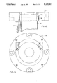
- FIG. 4 is a bottom plan view of the disposable pump assembly illustrated in FIG. 1;
- FIG. 5 is a top plan view of the disposable pump assembly illustrated in FIG. 1;
- FIG. 6 is a cross-sectional view taken on the line 6--6 of FIG. 1;
- FIG. 7 is a cross-sectional view taken on the line 7--7 of FIG. 1;
- FIG. 8 is a cross-sectional view taken on the line 8--8 of FIG. 1;
- FIG. 9 is a cross-sectional view taken on the line 9--9 of FIG. 1;
- FIG. 10 is a top plan view of an impeller for the disposable pump assembly of FIG. 1;
- FIG. 11 is a cross-sectional view taken on the line 11--11 of FIG. 10;
- FIG. 12 is a cross-sectional view of a motor-supporting mounting block for the disposable pump assembly of FIG. 1;
- FIG. 13 is a bottom plan view of the motor-supporting mounting block of FIG. 12.
- the reference numeral 20 designates generally a disposable pump assembly adapted to be driven by a motor 22 through an elongated shaft 24.
- the disposable pump assembly 20 includes a pump body 26 including a volute portion 28 and an elongated riser portion 30 extending upwardly from the volute portion 28.
- the riser portion 30 is integrally joined to the volute portion 28 by a neck 32 defining a restricted opening 34 leading from the riser portion 30 to the volute portion 28.
- the elongated shaft 24 is adapted to be inserted into the riser portion 30, through the restricted opening 34 and into the volute portion 28 of the pump body 26.
- the disposable pump assembly 20 also includes a shaft-receiving impeller 36 (see, also, FIGS.
- the volute portion 28 of the pump body 26 has an inlet opening 38 and an outlet opening 40 and an outlet tube 42 extends upwardly from the outlet opening 40 in spaced parallel relation to the riser portion 30.
- the riser portion 30 and the outlet tube 42 each have an upper end 30aand 42a, respectively, which is positioned so as to be remote from the volute portion 28.
- the upper end 30a of the riser portion 30 and the motor 22 each have corresponding rapid interconnect means for releasably securing the motor 22 to the riser portion 30 and, likewise, the upper end 42a of the outlet tube 40 includes means for releasably coupling a supply tube 44 thereto.
- volute portion 28 and the riser portion 30 are shaped generally cylindrical. It will also be seen from FIG. 9 that the restricted opening 34 defining the neck 32 between the volute portion 28 and the riser portion 30 also is shaped generally cylindrical. As best illustrated in FIG. 1, the neck 32 has a diameter substantially the same as the diameter of the elongated shaft 24 to define a bearing surface as at 34 therefor.
- the bearing surface as at 34 defined by the neck 32 forms a partial seal between the volute portion 28 and the riser portion 30.
- the partial seal is adapted to limit penetration of a liquid (such as ink) being pumped from a container (not shown) into the riser portion 30.
- the riser portion 30 also preferably includes at least one, and suitably a pair, of openings 46 disposed above the neck 32 for draining the liquid penetrating the partial seal.
- the inlet opening 38 in the volute portion 28 of the pump body 26 is disposed in a bottom wall 28a thereof.
- the inlet opening 38 is generally coaxial with the volute portion 28, riser portion 30 and neck 32 therebetween.
- the outlet opening 40 in the volute portion 28 of the pump body 26 is disposed radially outwardly of the inlet opening 38 so as to be disposed in a sidewall 28b thereof.
- the impeller 36 is generally cup-shaped and has a plurality of blades 36a extending radially therein.
- the rapid interconnect and drive means mentioned previously comprises at least in part a centrally disposed axial shaft-receiving portion 36b of the impeller 36.
- the shaft-receiving portion 36b and the elongated shaft 24 have corresponding non-circular cross-sections for driven movement of the impeller 36 by the motor 22, i.e., the non-circular cross-sections are, preferably, defined by first and second axially spaced hexagonally shaped regions 36b' and 36b".
- the first hexagonally shaped region 36b' is then advantageously dimensioned larger than the second hexagonally shaped region 36b".
- the elongated shaft 24 then includes correspondingly sized first and second axially spaced hexagonally shaped regions 24a' and 24a" for insertion into the shaft-receiving opening 36b of the impeller 36.
- the shaft-receiving portion 36b of the impeller 36 includes a socket-defining projection as at 50 extending from the bottom wall 36c of the impeller 36.
- the first hexagonally shaped region 36b' of the shaft-receiving portion 36b is disposed adjacent the blades 36a of the impeller 36 and above the socket-defining projection 50 whereas the second hexagonally shaped region 36b" is disposed in the projection 50.
- the socket-defining projection 50 extending from the bottom wall 36c of the impeller 36 includes an axially disposed opening 52 adapted to receive a detent 54 on the end 24b of the elongated shaft 24 in snap-fit fashion.
- the rapid interconnect means of the riser portion 30 is associated with the upper end 30a thereof and the releasable coupling means of the outlet tube 42 is also associated with the upper end 42a thereof.
- the rapid interconnect means and the releasable coupling means each are disposed in a common plane at generally the same distance above the volute portion 28.
- the motor 22 and the supply tube 44 are adapted to be quickly and easily releasably connected to the disposable pump assembly 20 at a point generally corresponding to the lid of a container of a liquid to be pumped.
- the rapid interconnect means of the riser portion 30 includes a collar 56 at the upper end 30a thereof.
- a motor-supporting mounting block 58 is associated with the motor 22 and adapted to fit over the collar 56 of the riser portion 30 (see, also, FIGS. 12 and 13).
- the motor-supporting mounting block 58 further includes at least one clamp assembly 60 adapted to cooperate with the collar 56 (see, in particular, FIG. 2).
- the releasable securing means of the outlet tube 42 it will be seen to include an externally threaded upper end 42a.
- This externally threaded upper end is adapted to receive an internally threaded coupling 62.
- the internally threaded coupling 62 will be provided on the end of the liquid supply tube 44 in conventional fashion.
- At least one and preferably a pair of support ribs 64 extend between the riser portion 30 and the outlet tube 42 of the pump body 26.
- the support ribs 64 are positioned generally parallel to and spaced above the volute portion 28 of the pump body 26 with at least one of the ribs 64 in proximity to the upper ends 30a and 42a of the riser portion 30 and the outlet tube 42, respectively.
- the support ribs 64 are formed of a plastic material so as to be integral with the riser portion 30 and the outlet tube 42 of the pump body 26.
- the pump body 26 is adapted to initially be formed of the plastic material by the thermoforming or blow molding process into two generally symmetrical pump body halves 26a and 26b.
- Each of the pump body halves 26a and 26b is matingly engageable with the other of the pump body halves, and with the impeller 36 confined within the volute portion 28, in such a manner as to fully define the volute portion 28, riser portion 30 and outlet tube 42.
- the pump body 26 finally is completely formed after the thermoforming or blow molding process has been completed by permanently securing the pump body halves 26a and 26b.
- the volute portion 28 of the pump body 26 includes a separate cap 66 defining the bottom wall 28a of the volute portion 28 as best shown in FIG. 1.
- the cap 66 has a central opening defining the inlet opening 38 and the volute portion 28 further includes a circular cap-retaining flange 28c extending thereabout.
- the cap 66 has a circular flange-receiving groove 66a adapted to cooperate with the circular cap-retaining flange 28c after insertion of the impeller 36 into the volute portion 28.
- each of the pump body halves such as 26a is formed with a flange 68a corresponding to a flange 68b of the other of the pump body halves such as 26b.
- the corresponding flanges 68a and 68b of the pump body halves 26a and 26b extend at least partially about the respective ones of the pump body halves 26a and 26b.
- the rapid interconnect means preferably includes a pair of clamp assemblies 60 carried by the mounting block 58.
- One of the clamp assemblies 60 is then disposed adjacent the outlet tube 42 with the other of the clamp assemblies being disposed generally diametrically opposite the outlet tube 42.
- the clamp assemblies 60 each are adapted to cooperate with the collar 56 of the riser portion 30 of the pump body 26.
- the pump body halves 26a and 26b are formed of very thin sheets of a material such as polypropylene or polyethylene that are vacuum formed in two different halves to make the shape of the volute portion 28.
- the two different halves also form the riser portion 30 and the integral outlet tube 42 leading, respectively, to the collar 56 and the threaded end 42a which comprises a hose connector. Since the shaft 24 normally remains connected to the motor 22, it is only necessary to insert the shaft 24 into the riser portion 30 until it can be snapped into the formed fitting 50 in the impeller 36 for use of the pump 20.
- the operator When it is desired to change to a different color ink, the operator simply disengages the clamp assemblies 60 from the collar 56. It is then a simple matter for the operator to pull the motor 22 away from the pump 20 thereby disengaging the shaft 24 from the impeller fitting 50, i.e., disengaging the detent 54 from the opening 52 in the fitting 50. Once this has been done, only the end of the shaft 24 need be cleaned of ink by wiping before the shaft 24 can be inserted into another pump 20 which can then be placed in a bucket containing a different color of ink for another run.
- the double-hexagon shape on the end of the shaft 24 is a unique feature of the invention. This meets with a corresponding double-hexagon shaft-receiving portion of the fitting 50 and the impeller 36. With this construction, there is better drivability of the impeller 36 while the detent 54 retains the connection between the shaft 24 and the impeller 36.
- the flanges 68a and 68b can be welded together using a solvent or heat sealed. It may also be advantageous for the flanges to be secured together in any other conventional fashion to render the pump body halves integral. In any event, with the present invention, it is possible to provide a disposable pump assembly that is quite inexpensive.
Landscapes
- Engineering & Computer Science (AREA)
- Mechanical Engineering (AREA)
- General Engineering & Computer Science (AREA)
- Structures Of Non-Positive Displacement Pumps (AREA)
Applications Claiming Priority (1)
| Application Number | Priority Date | Filing Date | Title |
|---|---|---|---|
| US30195389A | 1989-01-26 | 1989-01-26 |
Related Parent Applications (1)
| Application Number | Title | Priority Date | Filing Date |
|---|---|---|---|
| US30195389A Continuation | 1989-01-26 | 1989-01-26 |
Publications (1)
| Publication Number | Publication Date |
|---|---|
| US5122032A true US5122032A (en) | 1992-06-16 |
Family
ID=23165627
Family Applications (1)
| Application Number | Title | Priority Date | Filing Date |
|---|---|---|---|
| US07/725,921 Expired - Lifetime US5122032A (en) | 1989-01-26 | 1991-07-15 | Disposable pump assembly |
Country Status (2)
| Country | Link |
|---|---|
| US (1) | US5122032A (fr) |
| EP (1) | EP0379792A3 (fr) |
Cited By (11)
| Publication number | Priority date | Publication date | Assignee | Title |
|---|---|---|---|---|
| US7442003B1 (en) * | 2003-09-26 | 2008-10-28 | Fast Flow Llc | Pump |
| US20100080723A1 (en) * | 2008-09-30 | 2010-04-01 | Matthew Hollister | Overmolded rotor |
| US20140199165A1 (en) * | 2013-01-11 | 2014-07-17 | Liberty Pumps Inc. | Liquid pump |
| US10077771B2 (en) | 2014-12-30 | 2018-09-18 | Graco Minnesota, Inc. | Integral mounting system on axial reciprocating pumps |
| US10138891B2 (en) | 2015-01-26 | 2018-11-27 | Pemberton Patents Llc | Double suction pump with agitators |
| US10233940B2 (en) | 2015-10-22 | 2019-03-19 | Liberty Pumps, Inc. | Shaft seals and liquid pump comprising same |
| US11105333B2 (en) | 2015-01-26 | 2021-08-31 | Pemberton Patents Llc | Double suction pump |
| US11300112B2 (en) | 2020-03-31 | 2022-04-12 | Graco Minnesota Inc. | Pump drive system |
| US11512694B2 (en) | 2017-02-21 | 2022-11-29 | Graco Minnesota Inc. | Piston rod assembly for a fluid pump |
| US12366233B2 (en) | 2020-03-31 | 2025-07-22 | Graco Minnesota Inc. | Electrically operated pump for a plural component spray system |
| US12565877B2 (en) | 2020-03-31 | 2026-03-03 | Graco Minnesota Inc. | Electrically operated linear pump and pump drive |
Families Citing this family (3)
| Publication number | Priority date | Publication date | Assignee | Title |
|---|---|---|---|---|
| DE9301147U1 (de) * | 1993-01-28 | 1993-07-08 | BVS Beratung Verkauf Service Grafische Technik GmbH, 8901 Stadtbergen | Vorrichtung zur Versorgung eines Farbverbrauchers mit unterschiedlichen Farben |
| RU2176751C1 (ru) * | 2000-06-15 | 2001-12-10 | Носов Анатолий Александрович | Корпус жидкостного насоса |
| CN109397873A (zh) * | 2018-12-18 | 2019-03-01 | 陕西思维印务有限公司 | 一种集中供墨系统 |
Citations (26)
| Publication number | Priority date | Publication date | Assignee | Title |
|---|---|---|---|---|
| US2464936A (en) * | 1946-09-24 | 1949-03-22 | Ingersoll Rand Co | Supporting device for pumps |
| US2625720A (en) * | 1949-12-16 | 1953-01-20 | Internat Newspaper Supply Corp | Pump for type casting |
| US2868132A (en) * | 1952-04-24 | 1959-01-13 | Laing Nikolaus | Tank-pump |
| US2997957A (en) * | 1959-03-02 | 1961-08-29 | Entpr Machine And Dev Corp | Motor-driven pump |
| US3319939A (en) * | 1965-10-21 | 1967-05-16 | Dynamics Corp America | Rotatable beater assembly |
| US3335668A (en) * | 1966-02-01 | 1967-08-15 | Molon Motor & Coil Corp | Pump |
| GB1148848A (en) * | 1967-03-29 | 1969-04-16 | Hotpoint Ltd | Improvements in centrifugal pumps |
| US3604819A (en) * | 1969-10-14 | 1971-09-14 | United States Steel Corp | Impeller shaft assembly |
| US3707335A (en) * | 1971-01-25 | 1972-12-26 | Whirlpool Co | Water pump |
| US3779668A (en) * | 1972-05-11 | 1973-12-18 | Mcneil Corp | Stage for a centrifugal pump |
| US3814551A (en) * | 1971-03-18 | 1974-06-04 | Ecodyne Corp | Pump |
| US3837767A (en) * | 1973-05-31 | 1974-09-24 | Hydrometals Inc | Small pump |
| US3936221A (en) * | 1974-09-16 | 1976-02-03 | Goulds Pumps, Inc. | Vertical cantilever pump |
| US3947152A (en) * | 1974-07-01 | 1976-03-30 | Ace Envelope Manufacturing Corporation | Printing press centrifugal pump assembly |
| US3958894A (en) * | 1975-01-22 | 1976-05-25 | Weil-Mclain Co., Inc. | Fluid pumping assembly of a molded synthetic material |
| US3961382A (en) * | 1973-11-29 | 1976-06-08 | Associated Mills, Inc. | Hydrotherapy bath assembly |
| US4049364A (en) * | 1974-07-01 | 1977-09-20 | Ace Envelope Manufacturing Corporation | Removable impeller assembly for printing press centrifugal pump |
| US4185937A (en) * | 1978-08-25 | 1980-01-29 | General Electric Company | Fastening device with positive locking means |
| US4211519A (en) * | 1977-08-29 | 1980-07-08 | Cole-Parmer Instrument Company | Fluid pump and quick release mounting arrangement therefor |
| US4265839A (en) * | 1978-08-25 | 1981-05-05 | Baus Heinz Georg | Evaporation air humidifier |
| US4305902A (en) * | 1976-03-26 | 1981-12-15 | Owens-Illinois, Inc. | Method of making plastic articles |
| US4403923A (en) * | 1981-05-12 | 1983-09-13 | Korchin Herbert P | Submersible pump |
| EP0131326A2 (fr) * | 1983-07-06 | 1985-01-16 | POMPE F.B.M. S.p.A. | Pompe centrifuge pour des produits et matériaux très denses et/ou visqueux |
| US4557672A (en) * | 1984-01-13 | 1985-12-10 | Fred Levine | Ice machine pump rebuild kit |
| US4786239A (en) * | 1983-06-15 | 1988-11-22 | Hale Fire Pump Company | Pumping system selectably operable as a fire pump or a hydraulic pump |
| US4832573A (en) * | 1987-11-27 | 1989-05-23 | General Motors Corporation | Integral connection for plastic water pump impeller |
Family Cites Families (1)
| Publication number | Priority date | Publication date | Assignee | Title |
|---|---|---|---|---|
| US4808167A (en) * | 1987-01-16 | 1989-02-28 | Pacesetter Infusion, Ltd. | Medication infusion system with disposable pump/battery cassette |
-
1989
- 1989-11-28 EP EP19890312337 patent/EP0379792A3/fr not_active Withdrawn
-
1991
- 1991-07-15 US US07/725,921 patent/US5122032A/en not_active Expired - Lifetime
Patent Citations (26)
| Publication number | Priority date | Publication date | Assignee | Title |
|---|---|---|---|---|
| US2464936A (en) * | 1946-09-24 | 1949-03-22 | Ingersoll Rand Co | Supporting device for pumps |
| US2625720A (en) * | 1949-12-16 | 1953-01-20 | Internat Newspaper Supply Corp | Pump for type casting |
| US2868132A (en) * | 1952-04-24 | 1959-01-13 | Laing Nikolaus | Tank-pump |
| US2997957A (en) * | 1959-03-02 | 1961-08-29 | Entpr Machine And Dev Corp | Motor-driven pump |
| US3319939A (en) * | 1965-10-21 | 1967-05-16 | Dynamics Corp America | Rotatable beater assembly |
| US3335668A (en) * | 1966-02-01 | 1967-08-15 | Molon Motor & Coil Corp | Pump |
| GB1148848A (en) * | 1967-03-29 | 1969-04-16 | Hotpoint Ltd | Improvements in centrifugal pumps |
| US3604819A (en) * | 1969-10-14 | 1971-09-14 | United States Steel Corp | Impeller shaft assembly |
| US3707335A (en) * | 1971-01-25 | 1972-12-26 | Whirlpool Co | Water pump |
| US3814551A (en) * | 1971-03-18 | 1974-06-04 | Ecodyne Corp | Pump |
| US3779668A (en) * | 1972-05-11 | 1973-12-18 | Mcneil Corp | Stage for a centrifugal pump |
| US3837767A (en) * | 1973-05-31 | 1974-09-24 | Hydrometals Inc | Small pump |
| US3961382A (en) * | 1973-11-29 | 1976-06-08 | Associated Mills, Inc. | Hydrotherapy bath assembly |
| US3947152A (en) * | 1974-07-01 | 1976-03-30 | Ace Envelope Manufacturing Corporation | Printing press centrifugal pump assembly |
| US4049364A (en) * | 1974-07-01 | 1977-09-20 | Ace Envelope Manufacturing Corporation | Removable impeller assembly for printing press centrifugal pump |
| US3936221A (en) * | 1974-09-16 | 1976-02-03 | Goulds Pumps, Inc. | Vertical cantilever pump |
| US3958894A (en) * | 1975-01-22 | 1976-05-25 | Weil-Mclain Co., Inc. | Fluid pumping assembly of a molded synthetic material |
| US4305902A (en) * | 1976-03-26 | 1981-12-15 | Owens-Illinois, Inc. | Method of making plastic articles |
| US4211519A (en) * | 1977-08-29 | 1980-07-08 | Cole-Parmer Instrument Company | Fluid pump and quick release mounting arrangement therefor |
| US4185937A (en) * | 1978-08-25 | 1980-01-29 | General Electric Company | Fastening device with positive locking means |
| US4265839A (en) * | 1978-08-25 | 1981-05-05 | Baus Heinz Georg | Evaporation air humidifier |
| US4403923A (en) * | 1981-05-12 | 1983-09-13 | Korchin Herbert P | Submersible pump |
| US4786239A (en) * | 1983-06-15 | 1988-11-22 | Hale Fire Pump Company | Pumping system selectably operable as a fire pump or a hydraulic pump |
| EP0131326A2 (fr) * | 1983-07-06 | 1985-01-16 | POMPE F.B.M. S.p.A. | Pompe centrifuge pour des produits et matériaux très denses et/ou visqueux |
| US4557672A (en) * | 1984-01-13 | 1985-12-10 | Fred Levine | Ice machine pump rebuild kit |
| US4832573A (en) * | 1987-11-27 | 1989-05-23 | General Motors Corporation | Integral connection for plastic water pump impeller |
Cited By (33)
| Publication number | Priority date | Publication date | Assignee | Title |
|---|---|---|---|---|
| US7442003B1 (en) * | 2003-09-26 | 2008-10-28 | Fast Flow Llc | Pump |
| US20100080723A1 (en) * | 2008-09-30 | 2010-04-01 | Matthew Hollister | Overmolded rotor |
| US8444405B2 (en) | 2008-09-30 | 2013-05-21 | Matthew Hollister | Overmolded rotor |
| US10267312B2 (en) | 2013-01-11 | 2019-04-23 | Liberty Pumps, Inc. | Liquid pump |
| US20140199165A1 (en) * | 2013-01-11 | 2014-07-17 | Liberty Pumps Inc. | Liquid pump |
| US9719515B2 (en) * | 2013-01-11 | 2017-08-01 | Liberty Pumps, Inc. | Liquid pump |
| US10502206B2 (en) | 2014-12-30 | 2019-12-10 | Graco Minnesota Inc. | Pump rod and driving link with side-load reducing configuration |
| US11286926B2 (en) | 2014-12-30 | 2022-03-29 | Graco Minnesota Inc. | Pump rod and driving link with side-load reducing configuration |
| US11891991B2 (en) | 2014-12-30 | 2024-02-06 | Graco Minnesota Inc. | Displacement pump mounting and retention |
| US10094375B2 (en) | 2014-12-30 | 2018-10-09 | Graco Minnesota Inc. | Self-aligning mounting and retention system |
| US11873810B2 (en) | 2014-12-30 | 2024-01-16 | Graco Minnesota Inc. | Displacement pump mounting and retention |
| US11035359B2 (en) | 2014-12-30 | 2021-06-15 | Graco Minnesota Inc. | Displacement pump mounting and retention |
| US11927183B2 (en) | 2014-12-30 | 2024-03-12 | Graco Minnesota Inc. | Displacement pump mounting and retention |
| US11927184B2 (en) | 2014-12-30 | 2024-03-12 | Graco Minnesota Inc. | Displacement pump mounting and retention |
| US12421960B2 (en) | 2014-12-30 | 2025-09-23 | Graco Minnesota Inc. | Pump mounting and driving |
| US11396871B1 (en) | 2014-12-30 | 2022-07-26 | Graco Minnesota Inc. | Displacement pump mounting and retention |
| US10077771B2 (en) | 2014-12-30 | 2018-09-18 | Graco Minnesota, Inc. | Integral mounting system on axial reciprocating pumps |
| US11530697B2 (en) | 2014-12-30 | 2022-12-20 | Graco Minnesota Inc. | Displacement pump mounting and retention |
| US11873809B2 (en) | 2014-12-30 | 2024-01-16 | Graco Minnesota Inc. | Displacement pump mounting and retention |
| US11732708B2 (en) | 2014-12-30 | 2023-08-22 | Graco Minnesota Inc. | Displacement pump mounting and retention |
| US12196200B2 (en) | 2014-12-30 | 2025-01-14 | Graco Minnesota Inc. | Pump rod and driving link with side-load reducing configuration |
| US11105333B2 (en) | 2015-01-26 | 2021-08-31 | Pemberton Patents Llc | Double suction pump |
| US10138891B2 (en) | 2015-01-26 | 2018-11-27 | Pemberton Patents Llc | Double suction pump with agitators |
| US11629728B2 (en) | 2015-10-22 | 2023-04-18 | Liberty Pumps, Inc. | Shaft seals and liquid pump comprising same |
| US10233940B2 (en) | 2015-10-22 | 2019-03-19 | Liberty Pumps, Inc. | Shaft seals and liquid pump comprising same |
| US11512694B2 (en) | 2017-02-21 | 2022-11-29 | Graco Minnesota Inc. | Piston rod assembly for a fluid pump |
| US11891992B2 (en) | 2017-02-21 | 2024-02-06 | Graco Minnesota Inc. | Piston with sleeve for fluid pump |
| US11773842B2 (en) | 2017-02-21 | 2023-10-03 | Graco Minnesota Inc. | Removable piston rod sleeve for fluid pump |
| US12313061B2 (en) | 2017-02-21 | 2025-05-27 | Graco Minnesota Inc. | Fluid dispensing system having a piston rod and wear sleeve |
| US12366233B2 (en) | 2020-03-31 | 2025-07-22 | Graco Minnesota Inc. | Electrically operated pump for a plural component spray system |
| US12421946B2 (en) | 2020-03-31 | 2025-09-23 | Graco Minnesota Inc. | Pump drive system |
| US11300112B2 (en) | 2020-03-31 | 2022-04-12 | Graco Minnesota Inc. | Pump drive system |
| US12565877B2 (en) | 2020-03-31 | 2026-03-03 | Graco Minnesota Inc. | Electrically operated linear pump and pump drive |
Also Published As
| Publication number | Publication date |
|---|---|
| EP0379792A3 (fr) | 1990-10-03 |
| EP0379792A2 (fr) | 1990-08-01 |
Similar Documents
| Publication | Publication Date | Title |
|---|---|---|
| US5122032A (en) | Disposable pump assembly | |
| US4283645A (en) | Electrical drive motor, in particular for water pumps in the field of aquaria | |
| US4673081A (en) | Waste oil drain collector and storage container kit | |
| EP1954402B1 (fr) | Réservoir de liquide, ensemble de pulvérisation, et procédé d'utilisation associé | |
| EP0231862B1 (fr) | Cartouche de filtre à changement rapide et sa partie supérieure | |
| CN103534019B (zh) | 用于传递流体产品的装置 | |
| US20040217201A1 (en) | Spray gun container | |
| US5335806A (en) | Adapter ring for a paint can | |
| US5950874A (en) | Batching machine, in particular for dyes | |
| US4993457A (en) | Housing arrangement for a fluid pump and tank | |
| CA2615043A1 (fr) | Tubulure de remplissage pour recipient | |
| US4909409A (en) | Quick change spray paint receptacle apparatus | |
| US4813786A (en) | Fluid mixing unit | |
| US4695232A (en) | Central body to which are connected both a driving motor and a pump | |
| US11040360B2 (en) | Liquid supply assembly | |
| EP0314321A1 (fr) | Système de nettoyage | |
| EP0013942A3 (en) | Centrifugal pump for liquids containing solids | |
| US4394266A (en) | Pressure filter adapter and containment vessel | |
| CN213433905U (zh) | 喷流搅拌管 | |
| EP0534381B1 (fr) | Dispositif de vidange pour machines à laver ou similaires | |
| US2791227A (en) | Washing machine for milking equipment | |
| US4836405A (en) | Container for the reception of a pumpable product | |
| GB2325451A (en) | Rotary containers | |
| GB2187232A (en) | Rotary impeller pump for liquids | |
| US4382200A (en) | Stirrer motor support |
Legal Events
| Date | Code | Title | Description |
|---|---|---|---|
| FEPP | Fee payment procedure |
Free format text: PAYOR NUMBER ASSIGNED (ORIGINAL EVENT CODE: ASPN); ENTITY STATUS OF PATENT OWNER: SMALL ENTITY |
|
| STCF | Information on status: patent grant |
Free format text: PATENTED CASE |
|
| FEPP | Fee payment procedure |
Free format text: PAYOR NUMBER ASSIGNED (ORIGINAL EVENT CODE: ASPN); ENTITY STATUS OF PATENT OWNER: SMALL ENTITY Free format text: PAYER NUMBER DE-ASSIGNED (ORIGINAL EVENT CODE: RMPN); ENTITY STATUS OF PATENT OWNER: SMALL ENTITY |
|
| FPAY | Fee payment |
Year of fee payment: 4 |
|
| FPAY | Fee payment |
Year of fee payment: 8 |
|
| FPAY | Fee payment |
Year of fee payment: 12 |