US5122072A - Cam-lock busway joint assembly - Google Patents
Cam-lock busway joint assembly Download PDFInfo
- Publication number
- US5122072A US5122072A US07/630,653 US63065390A US5122072A US 5122072 A US5122072 A US 5122072A US 63065390 A US63065390 A US 63065390A US 5122072 A US5122072 A US 5122072A
- Authority
- US
- United States
- Prior art keywords
- conductors
- joint
- busway
- pair
- activating
- Prior art date
- Legal status (The legal status is an assumption and is not a legal conclusion. Google has not performed a legal analysis and makes no representation as to the accuracy of the status listed.)
- Expired - Lifetime
Links
- 239000004020 conductor Substances 0.000 claims abstract description 68
- 230000003213 activating effect Effects 0.000 claims abstract description 51
- 239000012212 insulator Substances 0.000 claims abstract description 14
- 230000001681 protective effect Effects 0.000 claims abstract description 7
- 230000000007 visual effect Effects 0.000 claims description 2
- 239000012777 electrically insulating material Substances 0.000 claims 1
- 239000011810 insulating material Substances 0.000 claims 1
- 230000002093 peripheral effect Effects 0.000 claims 1
- 238000003780 insertion Methods 0.000 abstract description 2
- 230000037431 insertion Effects 0.000 abstract description 2
- 238000007689 inspection Methods 0.000 description 3
- 238000000034 method Methods 0.000 description 2
- 230000004888 barrier function Effects 0.000 description 1
- 238000010276 construction Methods 0.000 description 1
- 239000000463 material Substances 0.000 description 1
- 238000012986 modification Methods 0.000 description 1
- 230000004048 modification Effects 0.000 description 1
- 230000035939 shock Effects 0.000 description 1
Images


Classifications
-
- H—ELECTRICITY
- H01—ELECTRIC ELEMENTS
- H01R—ELECTRICALLY-CONDUCTIVE CONNECTIONS; STRUCTURAL ASSOCIATIONS OF A PLURALITY OF MUTUALLY-INSULATED ELECTRICAL CONNECTING ELEMENTS; COUPLING DEVICES; CURRENT COLLECTORS
- H01R4/00—Electrically-conductive connections between two or more conductive members in direct contact, i.e. touching one another; Means for effecting or maintaining such contact; Electrically-conductive connections having two or more spaced connecting locations for conductors and using contact members penetrating insulation
- H01R4/28—Clamped connections, spring connections
- H01R4/50—Clamped connections, spring connections utilising a cam, wedge, cone or ball also combined with a screw
- H01R4/5008—Clamped connections, spring connections utilising a cam, wedge, cone or ball also combined with a screw using rotatable cam
Definitions
- the present invention relates to a means for making an electrical connection between an electrical conductor of a first busway section and an electrical conductor of a second busway section and more specifically to the use of a rotating cam mechanism for applying a clamping force on the joint connectors to provide a positive electrical connection.
- This invention includes a plurality of independently and cam operable joint connectors for connecting the electrical conductors of a first busway section to the electrical conductors of a second busway section.
- a rotating cam mechanism operated by an activating cap applies the force required for making a good electrical connection between the busway conductors and the joint connectors.
- a plurality of phase insulators electrically separate the joint connectors of opposite polarity from each other.
- a pair of electrically insulated frame halves are used to support the electrical connectors, the rotating cam mechanism, and the phase insulators. Four assembly rods, one in each corner of the frame, hold the assembly together.
- a cover plate placed over a joint inspection opening in the busway enclosure inhibits physical contact with live electrical conductors in the joint and also provides a means for locking the activating caps in the tightened position to prevent any loosening of the electrical connection. It also provides a visual indication that the joint connectors are in the proper position for operation.
- cam-lock joint assembly of this invention requires only a 1/4 turn of the activating caps to provide the clamping force required for a tight electrical connection.
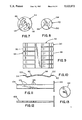
- FIG. 1 is an isometic view of two adjoining busway sections including an installed cover plate which covers the joint inspection opening between the two busway sections and locks the cam mechanism in the tightened position.
- FIG. 2 is an isometric view of a cam lock joint assembly.
- FIG. 3 is an exploded view of a cam lock joint assembly.
- FIG. 4 is a cross-sectional view along line 4--4 of FIG. 2 of a cam lock joint assembly showing the joint assembly in the loosened position prior to installing the busway electrical conductors.
- FIG. 5 is a cross-sectional view along line 5--5 of FIG. 2 of the joint assembly taken through the activating shaft.
- FIG. 6 is a cross-sectional view along line 4--4 of FIG. 2 of a cam lock joint assembly showing the joint in the tightened position with the busway conductors installed.
- FIG. 7 is a front view of the cam plate showing the oval and spiral slots.
- FIG. 8 is a back view of the activating cap showing the oval aperture.
- FIG. 9 is a top view of a joint connector.
- FIG. 10 is a side view of a joint connector.
- FIG. 11 is a top view of a cam activating shaft.
- FIG. 12 is an edge view of a cam activating shaft.
- FIG. 13 is a front view of the circular plate which is permanently attached to one end of the cam activating shaft.
- FIG. 2 An assembly as illustrated in FIG. 2 is used for connecting a plurality of electrical conductors 14 of a first busway section 18 with a plurality of electrical conductors 22 of a second adjoining busway section 26 as shown in FIG. 1.
- a protective enclosure 30 comprised of a trough 34 and a cover 38 surrounds and protects the conductors 14 and 22 from physical damage and provides protection against electrical shock.
- the assembly described herein relates to a low voltage, low amperage busway system although modifications will become apparent to adapt the assembly for higher rated busway systems.
- two indentical joint connectors 42 and 42' assembled in opposed relationship to each other form a pair of joint connectors 64 which are utilized to connect an electrical conductor 14 of the first busway section 18 with a corresponding electrical conductor 22 of the second busway section 26.
- a pair of cam plates 54 and a pair of clamping rods 58 operating together apply a clamping force on the pair of joint connectors 64 to provide a positive electrical connection with the busway conductors 14 and 22.
- a phase insulator 62 is placed between each pair of joint connectors 64 to separate the electrical phases from each other and an insulator 62 is also placed between the outer most pairs of joint connectors 64 and the protective enclosure 30 to separate the outer electrical phases from the protective enclosure 30.
- the joint connectors 42 and 42', cam plates 54, clamping rods 58, and phase insulators 62 are mounted between a pair of insulated frame halves 66 and 66'.
- the rods 70 are formed from an insulative material and are heated or otherwise deformed at opposite ends adjacent the outside of frame halves 66 and 66' to hold the joint pack assembly together.
- a cover plate 78 installed over a joint inspection opening 82 in the busway enclosure cover 38 provides a means as will be hereinafter further described for locking each pair of joint connectors 64 in a first position wherein each pair of joint connectors 64 is held tightly against the respective busway conductors 14 and 22.
- the cover plate 78 also provides a barrier to physical contact with the current carrying parts of the busway and joint assembly.
- a rectangularly shaped joint connector 42 or 42' includes a first end 90 which contacts the electrical conductor 14 of the first busway section 18, a second end 94 which contacts the electrical conductor 22 of the second busway section 26 and a plurality of fingers 96 being parallel to one another and running perpendicular to the ends 90 and 94 of the joint connector 42.
- each joint connector also includes an outward bow 98 running between the ends 90 and 94 and an outward offset 102 running parallel to the ends 90 and 94 of the joint connector 42 which combine to form a flattened W-shape when the joint connector 42 is viewed from the side.
- the offset 102 permits an easier insertion of the busway conductor 14 and 22 into the space between the pair of joint connectors 64.
- the clamping means comprises a pair of circular cam plates 54 which are rotated by an activating shaft 106.
- An electrically insulated activating cap 110 is attached to one end of the activating shaft 106 for the purpose of manually rotating the activating shaft 106 between a first position coinciding with a "closed” or “clamped” state and a second position coinciding with an "open” or “released” state of associated connectors 64.
- the cam plates 54 are rotated to the first position as shown in FIG. 6 they move a pair of clamping rods 58 which exert force on the bowed portion 98 of the opposed joint connectors 42 and 42'. This clamping force provides a good electrical connection between the joint connectors 42 and 42' and the respective electrical conductors 14 and 22 of the busway.
- Each cam plate 54 includes an oval slot 114 for the passage of the activating shaft 106 and a pair of spiral slots 118 equally spaced about the oval slot 114 for engaging the clamping rods 58.
- the activating shaft 106 includes a circular plate 122 permanently fixed to one end of the shaft 106 and a plurality of small notches 126 along edge of the shaft 106.
- the small notches 126 mark points for cutting the shaft off depending on the width of the busway conductors it is to be used with.
- the electrically insulated activating cap 110 is attached to the end of the activating shaft 106 opposite the circular plate 122.
- the activating cap 110 is generally shaped like a top hat, a rectangular box like portion 134 extending outward from a flat circular portion 130 as shown in FIG. 3.
- An oval aperture 138 extends from the surface of the flat circular portion 130 into the rectangular box like portion 134 to receive one end of the activating shaft 106.
- the joint pack assembly 74 consists of two insulated frame halves 66 and 66' assembled in opposed relationship to each other. Each half of the frame 66 and 66' includes an inside surface 142 and an outside surface 146. A plurality of figure 8-shaped apertures 150 connecting the inside surface 142 with the outside surface 146 are equally spaced apart along the longitudinal axis of the frame half 66 and 66'. The activating shafts 106 pass through the figure 8-shaped apertures 150. A plurality of narrow slots 154 for captivating the phase insulators 62 are equally spaced apart and parallel to one another on the inside surface 142 of the frame halves 66 and 66'. The slots 154 run perpendicular to the longitudinal axis of the frame halves 66 and 66'.
- a pluality of circular recesses 158 on the inside surface 142 are concentric with the figure 8-shaped apertures 150 and receive the cam plates 54.
- a plurality of circular recesses 160 on the outside surface 146 are also concentric with the figure 8-shaped apertures 150. These circular recesses 160 receive either the circular plates 122 which are permanently attached to one end of the activating shaft 106 or the activating caps 110 which are attached to the opposite end of the activating shaft 106.
- a plurality of recessed areas 164 on the inside surface 142 receive the joint connectors 42 and 42'.
- a plurality of oval slots 168 located in the circular recesses 158 receive the clamping rods 58.
- a round aperture 172, in each of the four corners of the frame half 66 and 66' receives the assembly rods 70 which hold the joint pack assembly 74 together as previously described.
- the cover plate 78 includes a plurality of substantially parallel rectangular slots 176 for locking for activating caps 110 in the first position.
- the slots 176 are evenly spaced apart along the vertical axis of the cover plate 78 and placed at an angle which coincides with the activating cap 110 in its first position.
- the slots 176 will permit the rectangular portion 134 of the activating caps 110 to pass through only when the activating caps 110 are in the first position wherein the joint connection is tight.
- the cover plate 78 is attached to the busway enclosure cover 38 by a plurality of screws 180 or other fastening means. When the cover plate 78 is secured to the busway enclosure cover 38, and the rectangular portions 134 of the activating caps 110 are protruding through the slots 176, the activating caps 110 are prohibited from rotating from their first position to their second position.
Landscapes
- Connections Arranged To Contact A Plurality Of Conductors (AREA)
Priority Applications (2)
| Application Number | Priority Date | Filing Date | Title |
|---|---|---|---|
| US07/630,653 US5122072A (en) | 1990-12-20 | 1990-12-20 | Cam-lock busway joint assembly |
| MX9102000A MX9102000A (es) | 1990-12-20 | 1991-11-08 | Conjunto de union para barra conectora de traba deleva. |
Applications Claiming Priority (1)
| Application Number | Priority Date | Filing Date | Title |
|---|---|---|---|
| US07/630,653 US5122072A (en) | 1990-12-20 | 1990-12-20 | Cam-lock busway joint assembly |
Publications (1)
| Publication Number | Publication Date |
|---|---|
| US5122072A true US5122072A (en) | 1992-06-16 |
Family
ID=24528043
Family Applications (1)
| Application Number | Title | Priority Date | Filing Date |
|---|---|---|---|
| US07/630,653 Expired - Lifetime US5122072A (en) | 1990-12-20 | 1990-12-20 | Cam-lock busway joint assembly |
Country Status (2)
| Country | Link |
|---|---|
| US (1) | US5122072A (es) |
| MX (1) | MX9102000A (es) |
Cited By (20)
| Publication number | Priority date | Publication date | Assignee | Title |
|---|---|---|---|---|
| US5655922A (en) * | 1994-10-31 | 1997-08-12 | Weidmuller Interface Gmbh | Modular control system |
| US6814628B2 (en) | 2001-06-27 | 2004-11-09 | Fci Americas Technology, Inc. | Modular lug block assembly |
| US20070026730A1 (en) * | 2005-07-29 | 2007-02-01 | Nippon Dics Co., Ltd. | Connector for solderless connection and plug connected to the connector |
| US7517235B2 (en) | 2006-12-28 | 2009-04-14 | General Electric Company | Press fit connection for mounting electrical plug-in outlet insulator to a busway aluminum housing |
| US20100012375A1 (en) * | 2008-07-18 | 2010-01-21 | Jur Arthur J | Electrical busway and offset coupling assembly therefor |
| US7819681B1 (en) * | 2009-06-19 | 2010-10-26 | Rodrigues Carlton R | Thermally efficient busway joint pack |
| US8177569B1 (en) | 2010-12-21 | 2012-05-15 | Schneider Electric USA, Inc. | Heat sink for a thermally efficient busway joint pack |
| US20130178086A1 (en) * | 2012-01-09 | 2013-07-11 | Johnson Electric International (Uk) Limited | Switching contactor |
| US8550830B1 (en) | 2012-06-01 | 2013-10-08 | General Electric Company | Connector for interconnecting three busway at its three ends |
| US8669472B2 (en) | 2011-08-26 | 2014-03-11 | Schneider Electric USA, Inc. | Applying compression to busbars in a busway assembly |
| US8847088B2 (en) | 2011-09-22 | 2014-09-30 | General Electric Company | Cover mounted handle operating mechanism with integrated interlock assembly for a busplug enclosure |
| US8926351B2 (en) | 2012-11-20 | 2015-01-06 | Schneider Electric USA, Inc. | Busway joint pack with heat sink insert |
| US9071028B2 (en) * | 2010-11-02 | 2015-06-30 | Sma Solar Technology Ag | Electrical connection between two busbars made of flat conductors and of an insulating layer disposed between the conductors |
| CN107560745A (zh) * | 2017-08-03 | 2018-01-09 | 东华大学 | 一种用于监测母线接头部位温度的测温装置 |
| CN107607208A (zh) * | 2017-08-03 | 2018-01-19 | 东华大学 | 一种母线槽接头测温装置 |
| US10367289B2 (en) * | 2015-09-24 | 2019-07-30 | Autonetworks Technologies, Ltd | Terminal connecting structure and connector device |
| US10518863B2 (en) * | 2016-04-22 | 2019-12-31 | Rolls-Royce Plc | Aircraft electrical network |
| CN112196478A (zh) * | 2020-11-09 | 2021-01-08 | 东营市瑞丰石油技术发展有限责任公司 | 一种复合式安全接头 |
| IT202000014110A1 (it) * | 2020-06-12 | 2021-12-12 | Iam Industrial Asset Man S R L | Blocco di giunzione per moduli di blindosbarra |
| CN118659159A (zh) * | 2024-06-13 | 2024-09-17 | 湖北兴和电力新材料股份有限公司 | 一种防护型母线连接装置 |
Citations (7)
| Publication number | Priority date | Publication date | Assignee | Title |
|---|---|---|---|---|
| US3180924A (en) * | 1963-06-28 | 1965-04-27 | Gen Electric | Busway connector |
| US3384854A (en) * | 1966-01-06 | 1968-05-21 | Square D Co | Plug-in bus duct |
| US4272646A (en) * | 1978-02-15 | 1981-06-09 | Broadhill Development Corporation | Bus conduit electrical distribution system |
| US4504101A (en) * | 1983-08-29 | 1985-03-12 | Gte Automatic Electric Inc. | Low insertion force connection arrangement |
| US4505527A (en) * | 1983-08-29 | 1985-03-19 | Gte Automatic Electric Inc. | Low insertion force connection arrangement |
| US4820177A (en) * | 1984-09-13 | 1989-04-11 | Square D Company | Electrical distribution system having specially formed and insulated bus bars |
| US4983132A (en) * | 1989-12-15 | 1991-01-08 | Amp Incorporated | Connector for mating bus bars |
-
1990
- 1990-12-20 US US07/630,653 patent/US5122072A/en not_active Expired - Lifetime
-
1991
- 1991-11-08 MX MX9102000A patent/MX9102000A/es unknown
Patent Citations (7)
| Publication number | Priority date | Publication date | Assignee | Title |
|---|---|---|---|---|
| US3180924A (en) * | 1963-06-28 | 1965-04-27 | Gen Electric | Busway connector |
| US3384854A (en) * | 1966-01-06 | 1968-05-21 | Square D Co | Plug-in bus duct |
| US4272646A (en) * | 1978-02-15 | 1981-06-09 | Broadhill Development Corporation | Bus conduit electrical distribution system |
| US4504101A (en) * | 1983-08-29 | 1985-03-12 | Gte Automatic Electric Inc. | Low insertion force connection arrangement |
| US4505527A (en) * | 1983-08-29 | 1985-03-19 | Gte Automatic Electric Inc. | Low insertion force connection arrangement |
| US4820177A (en) * | 1984-09-13 | 1989-04-11 | Square D Company | Electrical distribution system having specially formed and insulated bus bars |
| US4983132A (en) * | 1989-12-15 | 1991-01-08 | Amp Incorporated | Connector for mating bus bars |
Cited By (23)
| Publication number | Priority date | Publication date | Assignee | Title |
|---|---|---|---|---|
| US5655922A (en) * | 1994-10-31 | 1997-08-12 | Weidmuller Interface Gmbh | Modular control system |
| US6814628B2 (en) | 2001-06-27 | 2004-11-09 | Fci Americas Technology, Inc. | Modular lug block assembly |
| US20070026730A1 (en) * | 2005-07-29 | 2007-02-01 | Nippon Dics Co., Ltd. | Connector for solderless connection and plug connected to the connector |
| US7204719B2 (en) * | 2005-07-29 | 2007-04-17 | Nippon Dics Co., Ltd. | Connector for solderless connection and plug connected to the connector |
| US7517235B2 (en) | 2006-12-28 | 2009-04-14 | General Electric Company | Press fit connection for mounting electrical plug-in outlet insulator to a busway aluminum housing |
| US20100012375A1 (en) * | 2008-07-18 | 2010-01-21 | Jur Arthur J | Electrical busway and offset coupling assembly therefor |
| US7819681B1 (en) * | 2009-06-19 | 2010-10-26 | Rodrigues Carlton R | Thermally efficient busway joint pack |
| US9071028B2 (en) * | 2010-11-02 | 2015-06-30 | Sma Solar Technology Ag | Electrical connection between two busbars made of flat conductors and of an insulating layer disposed between the conductors |
| US8177569B1 (en) | 2010-12-21 | 2012-05-15 | Schneider Electric USA, Inc. | Heat sink for a thermally efficient busway joint pack |
| US8669472B2 (en) | 2011-08-26 | 2014-03-11 | Schneider Electric USA, Inc. | Applying compression to busbars in a busway assembly |
| US8847088B2 (en) | 2011-09-22 | 2014-09-30 | General Electric Company | Cover mounted handle operating mechanism with integrated interlock assembly for a busplug enclosure |
| US8845350B2 (en) * | 2012-01-09 | 2014-09-30 | Johnson Electric International (Uk) Limited | Switching contactor |
| US20130178086A1 (en) * | 2012-01-09 | 2013-07-11 | Johnson Electric International (Uk) Limited | Switching contactor |
| US8550830B1 (en) | 2012-06-01 | 2013-10-08 | General Electric Company | Connector for interconnecting three busway at its three ends |
| US8926351B2 (en) | 2012-11-20 | 2015-01-06 | Schneider Electric USA, Inc. | Busway joint pack with heat sink insert |
| US10367289B2 (en) * | 2015-09-24 | 2019-07-30 | Autonetworks Technologies, Ltd | Terminal connecting structure and connector device |
| US10737759B2 (en) * | 2016-04-22 | 2020-08-11 | Rolls-Royce Plc | Aircraft electrical network |
| US10518863B2 (en) * | 2016-04-22 | 2019-12-31 | Rolls-Royce Plc | Aircraft electrical network |
| CN107607208A (zh) * | 2017-08-03 | 2018-01-19 | 东华大学 | 一种母线槽接头测温装置 |
| CN107560745A (zh) * | 2017-08-03 | 2018-01-09 | 东华大学 | 一种用于监测母线接头部位温度的测温装置 |
| IT202000014110A1 (it) * | 2020-06-12 | 2021-12-12 | Iam Industrial Asset Man S R L | Blocco di giunzione per moduli di blindosbarra |
| CN112196478A (zh) * | 2020-11-09 | 2021-01-08 | 东营市瑞丰石油技术发展有限责任公司 | 一种复合式安全接头 |
| CN118659159A (zh) * | 2024-06-13 | 2024-09-17 | 湖北兴和电力新材料股份有限公司 | 一种防护型母线连接装置 |
Also Published As
| Publication number | Publication date |
|---|---|
| MX9102000A (es) | 1992-06-01 |
Similar Documents
| Publication | Publication Date | Title |
|---|---|---|
| US5406449A (en) | Pullout type electric disconnect switch | |
| US3340494A (en) | Electrical connector device | |
| US4038585A (en) | Insulating shutter mechanism for bus bars | |
| US4024441A (en) | Control center with insulated bus bars | |
| US20050057333A1 (en) | Circuit breaker lug cover and gasket | |
| US4820178A (en) | Outlet box for electric busway system | |
| KR930010604B1 (ko) | 플럭-인 모선로 섹숀 | |
| US4025747A (en) | Circuit interrupter stab assembly with self-aligning clip type contact | |
| CA1095159A (en) | Busway plug assembly | |
| US8864510B2 (en) | Bolt free electrical bus connector | |
| US6649838B1 (en) | Safety electrical outlet | |
| EP0992087A1 (en) | Bolted electrical connecting device for multiple electrical conductors | |
| CA2055129A1 (en) | Cam-lock busway joint assembly | |
| US3531758A (en) | Bus bar assembly | |
| CA2245973C (en) | A strain-relief system for a folding plug and connector system | |
| CA1084092A (en) | High current electrical joint apparatus | |
| EP0788205A2 (en) | Improvements in and relating to electrical distribution equipment | |
| CA1134000A (en) | Cover plate for electrical connector | |
| US4906958A (en) | Snap-on floating handle tie for multi-pole circuit breakers | |
| DE4312770A1 (de) | Phasenstromabtrennung für einen Schalter | |
| JPS6114721B2 (es) | ||
| GB2310768A (en) | Distribution equipment for a wall mountable consumer unit | |
| EP1296340B1 (de) | Klemmenabdeckkappe für die Anschlussklemmen eines mehrphasigen elektrischen Schaltgerätes | |
| US20240047914A1 (en) | Flexible Outlet Cover Device | |
| US4505533A (en) | Apparatus for clamping electric conductors, particularly wires |
Legal Events
| Date | Code | Title | Description |
|---|---|---|---|
| AS | Assignment |
Owner name: SQUARE D COMPANY, PALATINE, IL A CORP. OF DE Free format text: ASSIGNMENT OF ASSIGNORS INTEREST.;ASSIGNORS:ARN, GARY D.;MCGOLDRICK, GILBERT A.;O'NAN, GLENN S.;AND OTHERS;REEL/FRAME:005528/0331;SIGNING DATES FROM 19901211 TO 19901219 |
|
| STCF | Information on status: patent grant |
Free format text: PATENTED CASE |
|
| FPAY | Fee payment |
Year of fee payment: 4 |
|
| FEPP | Fee payment procedure |
Free format text: PAYOR NUMBER ASSIGNED (ORIGINAL EVENT CODE: ASPN); ENTITY STATUS OF PATENT OWNER: LARGE ENTITY |
|
| FPAY | Fee payment |
Year of fee payment: 8 |
|
| FPAY | Fee payment |
Year of fee payment: 12 |
|
| SULP | Surcharge for late payment |
Year of fee payment: 11 |