US5134782A - Coordinate-measuring machine - Google Patents
Coordinate-measuring machine Download PDFInfo
- Publication number
- US5134782A US5134782A US07/651,143 US65114391A US5134782A US 5134782 A US5134782 A US 5134782A US 65114391 A US65114391 A US 65114391A US 5134782 A US5134782 A US 5134782A
- Authority
- US
- United States
- Prior art keywords
- column
- carriage
- rotary
- coordinate
- displacement
- Prior art date
- Legal status (The legal status is an assumption and is not a legal conclusion. Google has not performed a legal analysis and makes no representation as to the accuracy of the status listed.)
- Expired - Fee Related
Links
Images


Classifications
-
- B—PERFORMING OPERATIONS; TRANSPORTING
- B23—MACHINE TOOLS; METAL-WORKING NOT OTHERWISE PROVIDED FOR
- B23Q—DETAILS, COMPONENTS, OR ACCESSORIES FOR MACHINE TOOLS, e.g. ARRANGEMENTS FOR COPYING OR CONTROLLING; MACHINE TOOLS IN GENERAL CHARACTERISED BY THE CONSTRUCTION OF PARTICULAR DETAILS OR COMPONENTS; COMBINATIONS OR ASSOCIATIONS OF METAL-WORKING MACHINES, NOT DIRECTED TO A PARTICULAR RESULT
- B23Q1/00—Members which are comprised in the general build-up of a form of machine, particularly relatively large fixed members
- B23Q1/25—Movable or adjustable work or tool supports
- B23Q1/44—Movable or adjustable work or tool supports using particular mechanisms
- B23Q1/48—Movable or adjustable work or tool supports using particular mechanisms with sliding pairs and rotating pairs
- B23Q1/4804—Movable or adjustable work or tool supports using particular mechanisms with sliding pairs and rotating pairs a single rotating pair followed perpendicularly by a single sliding pair
-
- B—PERFORMING OPERATIONS; TRANSPORTING
- B23—MACHINE TOOLS; METAL-WORKING NOT OTHERWISE PROVIDED FOR
- B23Q—DETAILS, COMPONENTS, OR ACCESSORIES FOR MACHINE TOOLS, e.g. ARRANGEMENTS FOR COPYING OR CONTROLLING; MACHINE TOOLS IN GENERAL CHARACTERISED BY THE CONSTRUCTION OF PARTICULAR DETAILS OR COMPONENTS; COMBINATIONS OR ASSOCIATIONS OF METAL-WORKING MACHINES, NOT DIRECTED TO A PARTICULAR RESULT
- B23Q1/00—Members which are comprised in the general build-up of a form of machine, particularly relatively large fixed members
- B23Q1/25—Movable or adjustable work or tool supports
- B23Q1/44—Movable or adjustable work or tool supports using particular mechanisms
- B23Q1/48—Movable or adjustable work or tool supports using particular mechanisms with sliding pairs and rotating pairs
- B23Q1/4852—Movable or adjustable work or tool supports using particular mechanisms with sliding pairs and rotating pairs a single sliding pair followed perpendicularly by a single rotating pair
- B23Q1/4871—Movable or adjustable work or tool supports using particular mechanisms with sliding pairs and rotating pairs a single sliding pair followed perpendicularly by a single rotating pair followed parallelly by a single sliding pair
-
- G—PHYSICS
- G01—MEASURING; TESTING
- G01B—MEASURING LENGTH, THICKNESS OR SIMILAR LINEAR DIMENSIONS; MEASURING ANGLES; MEASURING AREAS; MEASURING IRREGULARITIES OF SURFACES OR CONTOURS
- G01B5/00—Measuring arrangements characterised by the use of mechanical techniques
- G01B5/004—Measuring arrangements characterised by the use of mechanical techniques for measuring coordinates of points
- G01B5/008—Measuring arrangements characterised by the use of mechanical techniques for measuring coordinates of points using coordinate measuring machines
-
- G—PHYSICS
- G05—CONTROLLING; REGULATING
- G05B—CONTROL OR REGULATING SYSTEMS IN GENERAL; FUNCTIONAL ELEMENTS OF SUCH SYSTEMS; MONITORING OR TESTING ARRANGEMENTS FOR SUCH SYSTEMS OR ELEMENTS
- G05B19/00—Program-control systems
- G05B19/02—Program-control systems electric
- G05B19/42—Recording and playback systems, i.e. in which the program is recorded from a cycle of operations, e.g. the cycle of operations being manually controlled, after which this record is played back on the same machine
- G05B19/423—Teaching successive positions by walk-through, i.e. the tool head or end effector being grasped and guided directly, with or without servo-assistance, to follow a path
-
- G—PHYSICS
- G05—CONTROLLING; REGULATING
- G05B—CONTROL OR REGULATING SYSTEMS IN GENERAL; FUNCTIONAL ELEMENTS OF SUCH SYSTEMS; MONITORING OR TESTING ARRANGEMENTS FOR SUCH SYSTEMS OR ELEMENTS
- G05B2219/00—Program-control systems
- G05B2219/30—Nc systems
- G05B2219/37—Measurements
- G05B2219/37193—Multicoordinate measuring system, machine, cmm
-
- Y—GENERAL TAGGING OF NEW TECHNOLOGICAL DEVELOPMENTS; GENERAL TAGGING OF CROSS-SECTIONAL TECHNOLOGIES SPANNING OVER SEVERAL SECTIONS OF THE IPC; TECHNICAL SUBJECTS COVERED BY FORMER USPC CROSS-REFERENCE ART COLLECTIONS [XRACs] AND DIGESTS
- Y02—TECHNOLOGIES OR APPLICATIONS FOR MITIGATION OR ADAPTATION AGAINST CLIMATE CHANGE
- Y02P—CLIMATE CHANGE MITIGATION TECHNOLOGIES IN THE PRODUCTION OR PROCESSING OF GOODS
- Y02P90/00—Enabling technologies with a potential contribution to greenhouse gas [GHG] emissions mitigation
- Y02P90/02—Total factory control, e.g. smart factories, flexible manufacturing systems [FMS] or integrated manufacturing systems [IMS]
Definitions
- Coordinate-measuring machines are also known which do not measure in a Cartesian coordinate system but rather in spherical or cylindrical coordinates.
- British Patent 1,498,009 describes a coordinate-measuring machine in which the probe head is movably mounted by means of three articulations arranged one behind the other. The position of the probe head in this machine is determined by angle measurements at the respective articulations.
- a coordinate-measuring machine of similar construction is known from U.S. Pat. No. 4,240,205, wherein the probe head is mounted on a vertically displaceable spindle which, in turn, is guided in a single plane via three articulations which involve vertically oriented axes of rotation. The position of the spindle in the plane is measured by means of a scale and a rotary-angle transmitter.
- EP-A-0,342,267 discloses a coordinate-measuring machine in the form of a column which carries a probe head which is vertically displaceable and is movably guided by hand in a plane and can also be rotated around its longitudinal axis.
- this known machine it is not readily possible to equip this known machine with drives.
- the column is displaceable pursuant to operation of two linearly acting drives in the horizontal coordinates (x) and (y), and the workpiece to be measured is mounted to a rotary table.
- This machine is not of compact construction, and it is difficult to avoid bending moments in the transmission of y-axis drive forces, which act far outside the center of gravity of the column, to the displaceable column.
- the object of the present invention is to provide a coordinate-measuring machine which is of the simplest possible but stable construction and permits precise measurements.
- the invention achieves this object in a coordinate-measuring machine in which a column is displaceable linearly in one direction, in which a measurement arm (with probe head) is keyed to and guided on the column for vertical displacement, and in which the column is mounted for rotation about a vertical axis (A); the linear displaceability results from mounting the column to a linearly guided carriage and measurement systems for introducing and/or detecting rotational displacement of the column.
- the coordinate-measuring machine of the invention has only two linear axes, and the third linear axis, which is otherwise customary, is replaced by a pivot bearing.
- Highly accurate pivot bearings can be produced at considerably less expense than linear guides in the lengths customary for coordinate-measuring machines while satisfying the demands as to precision in guidance. Varying moments do not occur during a measurement, since the measurement arm of the machine is rigid and its length is constant.
- the entire coordinate-measuring machine can be very compact, since the column which carries the measurement arm is linearly displaceable in only one horizontal coordinate direction, and since displacement of the probe head in the second horizontal coordinate direction is via rotary movement of the column. Furthermore, since work-contacting measurements in the second horizontal direction involve essentially only rotary displacement of the measurement arm and its probe head, these are essentially the only factors affecting moment-of-inertia considerations; thus, relatively high acceleration can be obtained for work-contacting displacements, and measurements can be effected rapidly.
- the coordinate-measuring machine prefferably has a turntable for rotatably mounting a workpiece to be measured, with turntable rotation about a second vertical axis.
- the vertical plane which contains the two axes of rotation--that of the column and that of the turntable-- is substantially parallel to the linear direction of carriage displaceability, whereby the column is displaceable toward or away from the turntable and its workpiece.
- the coordinate-measuring machine advantageously has a control module which is so programmed that it coordinates the two rotary displacements in the desired manner.
- the vertical column can be totally mounted to the linearly guided carriage, in which case antifriction bearings can separately provide the stabilizing functions of upper radial location at an elevation vertically spaced above a combined radial/thrust bearing for both axial support and lower radial location.
- the rotatable column is mounted for radial location in the carriage and if axial support and location are derived from a stationary part of the machine table which carries the guide for the carriage.
- Such an arrangement results in a particularly stable construction, since freedom for column rotation about its vertical axis is then independent of the vertical-support function which is borne directly by the stationary machine table;
- the axial bearing is a surface bearing, and vertical stability against tilting of the rotary axis of the column is achieved by widely spaced air bearings reacting against the smooth flat horizontal plane of the machine table.
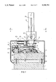
- FIG. 1 is a view in end elevation of a first coordinate-measuring machine of the invention, the view being partly broken-away and in vertical section to show detail of supporting and actuating mechanical relationships;
- FIG. 2 is a plan view of the machine of FIG. 1, with cover plate removed, showing at I--I the vertical-section plane of FIG. 1, and a portion of FIG. 2 being in section at the plane II--II of FIG. 1;
- FIG. 3 is a view similar to FIG. 1, for a second embodiment of the invention.
- FIG. 4 is a view similar to FIG. 2, for the embodiment of FIG. 3, showing at III--III the vertical-section plane of FIG. 3, and a portion of FIG. 4 being in section at the plane IV--IV of FIG. 3;
- FIG. 5 is a view similar to FIGS. 1 and 3, for a third embodiment of the invention.
- FIG. 6 is a view in side elevation of the embodiment of FIG. 5, taken partly in vertical section in the plane VI--VI of FIG. 5, and showing at V-V the vertical-section plane of FIG. 5;
- FIG. 7 is a simplified block diagram of the control system used for the coordinate-measuring machine of FIGS. 1 and 2.
- the coordinate-measuring machine of FIGS. 1 and 2 has a machine table 2 which rests via four vibration dampers 4 on the foundation 1 of the machine; only two (4a, 4b) of these vibration dampers are visible in FIG. 1.
- Table 2 provides a flat horizontal surface for three spaced air bearings 6a, b, c, at the base 5 of an upstanding column 8.
- Column 8 is linearly displaceable along this table surface and is also rotatable about its vertical axis A, as will be more fully described.
- a carriage 11 is guided for linear horizontal displacement in the direction of double-headed arrow X in FIG. 2, relying on six air bearings 12a-f which react with three exposed elongate surfaces of a guide ledge 10 that is secured to a side of table 2.
- Carriage 11 is driven by a motor 27 and by a transmission 28 to a smooth elongate shaft 29, which extends through carriage 11; rotation of shaft 29 can be translated into longitudinal displacement of carriage 11, illustratively by a so-called roll-ring transmission on the carriage. Roll-ring transmissions are known per se and therefore detail of this transmission on carriage 11 is not shown.
- Longitudinal displacement of carriage 11 is tracked by a photoelectric sensor 26 which scans a scale 25 secured to the guide ledge 10.
- a reduced cylindrical lower end portion 7 of column 8 provides connection to the column base 5, and portion 7 is inserted in and mounted to the inner ring of a radial bearing 13, the outer ring of which is mounted to carriage 11.
- the radial bearing 13 makes it possible to rotate column 8 about its axis A and with respect to the carriage 11, as indicated by double-headed arrow ⁇ in FIG. 2.
- the base 5 is a fixed part of column 8; therefore, base 5 axially supports column 8 via the air bearings 6a-c, in reaction with the surface of table 2 while also freely accommodating column rotation about axis A.
- the relatively large base spacings between air bearings 6a-c will be seen to prevent wobbling or tilting of column 8, whether in the course of rotary displacement of column 8 or in the course of linear displacement of the carriage 11.
- the carriage 11 carries a motor 16 which drives a friction-wheel transmission 17, engaged to a disk 18 that is attached to column 8.
- the angular extent ⁇ of the rotary displacement is tracked by a photoelectric sensor 14 mounted to carriage 11 and positioned to scan a graduated circular scale 15 secured to base 5 of column 8.
- column 8 Drives and measurement systems in the lower region of column 8 are protected by a cover 3, having an elongate slot 3' in its upper part, and extending in the X-direction of guidance.
- a cylindrical portion of column 8 extends through slot 3', and in the region above cover 3, column 8 is rectangular, being shown to be of square section and providing rotationally keyed and vertically displaceable guidance of a carriage 9, in the direction of the double-headed arrow Z of FIG. 1.
- Carriage 9 mounts the measurement arm 21 of the coordinate-measuring machine, and a probe head 22 is shown attached to the front end of arm 21.
- Linear Z-direction movement of carriage 9 is measured by a photoelectric sensor 20 which tracks a scale 19 secured to column 8.
- the drive 97 for Z-direction displacement of carriage 9 is not shown in FIGS. 1 and 2, but it is schematically indicated in FIG. 7 and will be understood to be carried within column 8.
- a turntable 23 is mounted for rotation about a vertical axis B, pursuant to motor drive by means 24.
- the axis A of column-8 rotation and the axis B of turntable-23 rotation have a longitudinally spaced parallel relation, defining a vertical plane which is preferably parallel and at least substantially parallel to the X-direction of carriage (11) guidance.
- Turntable 23 will be understood to be adapted for mounting reception of a workpiece to be measured, and workpiece rotation will be understood to be measured in terms of angular displacement ⁇ , sensed by photoelectric means 94 tracking a circumferential scale associated with turntable 23, as schematically indicated in FIG. 7.
- the probe head 22 is moved by means of the carriages 11 and 9 in the two orthogonal coordinate directions X and Z, pursuant to the control of their respective drive means 16 and 97.
- the conventional third-coordinate direction is omitted, being replaced by sluing displacement ⁇ of column 8 about axis A.
- the probe head is subjected to an arcuate displacement which is of greater or lesser extent depending upon the effective length r of the measurement arm.
- Control of linear and angular displacements in the coordinate-measuring machine of FIGS. 1 and 2 is effected by a special control module 100 (see FIG. 7) having connections to the computer 101 of the coordinate-measuring machine as well as to an operating panel 102.
- panel 102 By means of panel 102, the user determines the desired movements, as is customary in three orthogonal linear-displacement directions x, y and z.
- control module 100 Also connected to the control module 100 are the respective transmitted outputs of the photoelectric sensors 20 and 26 by which the linear movement X of the carriage 11 and the linear movement Z of the carriage 9 are measured, as well as the transmitted outputs of photoelectric angle sensor 14 (for the angle ⁇ of column-8 rotation) and of the sensor 94 (for the angle ⁇ of turntable-23 rotation).
- the control module 100 is additionally connected to drive motor 16 for rotation of the column 8, to motor 24 for turntable-23 rotation, to motor 27 for X-displacement of carriage 11, as well as to motor 97 (not shown in FIGS. 1 and 2) for Z-displacement of carriage 9.
- FIGS. 3 and 4 The coordinate-measuring machine of FIGS. 3 and 4 is only slightly modified, as compared with that of FIGS. 1 and 2. Identical parts having the same function have been provided with reference numbers which have been incremented by 30 and therefore need not be further explained.
- One difference from the embodiment of FIGS. 1 and 2 is that the carriage, which is horizontally displaceable in the X-direction and which is designated 41 in FIGS. 3 and 4, is driven by two linear drive units 58a and 58b which are coupled via a shaft to a common drive motor 57.
- linear-drive systems are known per se, as for example the product known Neff-Wiesel WO3-ZRT, available from Neff Gewindespindeln GmbH, Waldenbuch, Federal Republic of Germany; such a linear-drive system relies upon an endless toothed belt (not shown) within each of two spaced guides 59a, 59b, both belts being driven by motor 57, and with a pick-off connection from each belt to carriage, via an elongate slot (not shown) in the involved guide.
- the relatively light carriage 41 is moved by these linear drive units.
- FIGS. 3 and 4 permits of a possible incremental lateral component of carriage-41 displacement, perpendicular to the X-direction, as well as a possible increment of rotation about the vertical. Therefore, without special additional measures, the position of the probe head 52 on the measurement arm 51 of the coordinate-measuring machine cannot be reliably determined.
- Such an additional measure is achieved by providing, adjacent the longitudinal measurement scale 55 (which is at lateral offset on the one side of the column 38 that is displaced by carriage 41), a correction track comprising additional rulings 60 in the form of parallel longitudinal lines, i.e., in the X-direction of carriage guidance This correction track is scanned by two longitudinally spaced photoelectric sensors 56a and 56b.
- Such errors in position of the probe head 52 as are attributable to incremental rotation of carriage 41 about the vertical can be determined by taking the difference between the measurement values sensed by the two sensors 56a and 56b and can be used in known manner for correction of the position of the probe head 52, in that the measured difference is multiplied by the ratio which the longitudinal distance r (between rotary axis A and the work-contact point of the probe head 52) bears to the longitudinal distance between the two sensors 56a and 56b.
- Bodily lateral incremental displacement of the carriage 41 i.e., perpendicular to the X-direction of guidance is detected by taking the average value of the transmitted output signals of the two sensors 56a, 56b.
- a third photoelectric sensor 56c scans the longitudinal-displacement scale track 55 and supplies the output signal which indicates position in the direction X.
- the coordinate-measuring machine of FIGS. 3 and 4 is further shown to include two photoelectric transmitters 44a and 44b, for dual scanning of a graduated circle at 45, whereby to measure rotary displacement of column 38 about axis A.
- This dual scanning serves, in the same way as the described measurement of incremental lateral displacement and rotation of the carriage 41, to increase the precision of machine measurement.
- Control of the machine of FIGS. 3 and 4 is effected essentially in the same way as described for FIGS. 1 and 2, in connection with FIG. 7, except that, in FIGS. 3 and 4, the measurement values of the correction systems are also detected and used in calculating the work-contact position of the probe that is mounted to probe head 52.
- the measurement values of the correction systems are also detected and used in calculating the work-contact position of the probe that is mounted to probe head 52.
- systematic deviations of the measurement values are determined in a prior calibration process and are stored in the machine's computer, as correction values for use in computer calculation of the true position of the probe element.
- the vertical column 38 of the machine of FIGS. 3 and 4 is located for rotary displacement solely by a simple radial bearing 43 in carriage 41, and column 38 is axially supported, via three air bearings 36a-c in the base 35 of column 38, directly on the flat upper surface of table 32.
- a different solution is shown for support of the vertical column 68.
- the coordinate-measuring machine of FIGS. 5 and 6 does not have a flat-surface machine table. Instead, an upwardly open support part 62 of U-shaped section is mounted on the four vibration dampers 64a-d, and two parallel guide ledges 70a and 70b are fixed to the respective upper ends of the side walls of the U-shaped section.
- a carriage 71 spans both of these guide ledges 70a and 70b, being shown supported via a single air bearing 72a which rides the flat upper surface of guide ledge 70a and via two longitudinally spaced air bearings 72b, 72c which ride the flat upper surface of guide ledge 70b; in addition, opposed pairs of air bearings 72d, 72e (72f, 72g) at each of two longitudinally spaced locations, ride the opposed vertical surfaces of guide ledge 70b, to assure longitudinal fidelity of carriage 71, throughout its path of displaceability in the X-direction, pursuant to rotation of a drive spindle 89.
- a rotary-bearing assembly 71a which performs both radial-bearing and axial-bearing functions is mounted centrally in the carriage 71; these functions are symbolized by vertically spaced antifriction bearing rings, designated 73 and 66.
- the lower part of the cylindrical base 67 of column 68 is fixed to an annular flange part 78 which carries the graduated annulus 75 for measurement of rotary displacement ⁇ about axis A; in addition, flange 78 is engaged by the friction-wheel transmission 77 for rotary displacement of column 68 pursuant to drive by motor 76.
- Two photoelectric sensors 74a and 74b are fixedly mounted to rotary-bearing part 71a (and are therefore fixedly mounted to carriage 71) in position to scan the graduated annulus 75 for measurement of rotary displacement about axis A.
- Linear displacement of carriage 71 is measured by a photoelectric sensor 86, which scans an elongate scale 85 on the guide ledge 70a.
- the center of gravity of column 68 is relatively high, and no large base is available to avoid or prevent inertial tilting displacements; for stabilizing purposes, four compensation weights 65a-d are suspended from the bottom of carriage 71. These weights assure that the center of gravity of all parts driven by spindle 89 are approximately where the drive also acts on carriage 71. In this way, tilting of column 68 is prevented during the course of carriage displacement.
- Magazine 91 is so arranged and oriented that each of the various probe pins can be brought into an available storage location by the measurement arm 81, involving only pure linear displacement in the displacement direction X. This is possible after the measurement arm 81 has been indexed rearward from the measurement-region position shown in FIG. 6, involving such rotation by drive means 76 and about axis A that the measurement arm 81 is parallel to the direction X, and is pointed toward the probe pin to be newly chucked.
- each of the coordinate-measuring machines of FIGS. 1 to 4 can be similarly equipped with such a magazine.
- FIGS. 5 and 6 those other parts as have not been described will be understood to correspond functionally to similar parts of the embodiment of FIGS. 1 and 2 and, therefore, have been provided with reference numbers which are incremented by sixty, above corresponding reference numbers of FIGS. 1 and 2.
Landscapes
- Engineering & Computer Science (AREA)
- Physics & Mathematics (AREA)
- General Physics & Mathematics (AREA)
- Mechanical Engineering (AREA)
- Robotics (AREA)
- Automation & Control Theory (AREA)
- Length Measuring Devices With Unspecified Measuring Means (AREA)
- A Measuring Device Byusing Mechanical Method (AREA)
Applications Claiming Priority (2)
| Application Number | Priority Date | Filing Date | Title |
|---|---|---|---|
| DE4005292 | 1990-02-20 | ||
| DE4005292A DE4005292A1 (de) | 1990-02-20 | 1990-02-20 | Koordinatenmessgeraet |
Publications (1)
| Publication Number | Publication Date |
|---|---|
| US5134782A true US5134782A (en) | 1992-08-04 |
Family
ID=6400564
Family Applications (1)
| Application Number | Title | Priority Date | Filing Date |
|---|---|---|---|
| US07/651,143 Expired - Fee Related US5134782A (en) | 1990-02-20 | 1991-02-06 | Coordinate-measuring machine |
Country Status (4)
| Country | Link |
|---|---|
| US (1) | US5134782A (fr) |
| EP (1) | EP0443422B1 (fr) |
| JP (1) | JP2933732B2 (fr) |
| DE (2) | DE4005292A1 (fr) |
Cited By (22)
| Publication number | Priority date | Publication date | Assignee | Title |
|---|---|---|---|---|
| US5396712A (en) * | 1992-11-12 | 1995-03-14 | Carl Zeiss Stiftung | Coordinate measuring device |
| US5505003A (en) * | 1993-10-08 | 1996-04-09 | M&M Precision Systems Corporation | Generative measuring system |
| WO1996036847A1 (fr) * | 1995-05-16 | 1996-11-21 | Brown & Sharpe Manufacturing Company | Machine de mesure de coordonnees possedant un bras articule |
| US5646732A (en) * | 1995-04-21 | 1997-07-08 | Dieter Gerlach | Coordinate measuring system |
| WO1997043595A1 (fr) * | 1996-05-14 | 1997-11-20 | Tsk America, Inc. | Procede et appareil de positionnement couple par translation et rotation |
| US6015473A (en) * | 1995-08-07 | 2000-01-18 | Immersion Corporation | Method for producing a precision 3-D measuring apparatus |
| US6195618B1 (en) | 1998-10-15 | 2001-02-27 | Microscribe, Llc | Component position verification using a probe apparatus |
| US20020000047A1 (en) * | 1998-05-11 | 2002-01-03 | Yukiji Yoda | Work form-measuring method and device, and coordinate-measuring machine |
| US6438857B2 (en) * | 1999-12-03 | 2002-08-27 | Carl-Zeiss Stiftung | Coordinate measurement device |
| US6697748B1 (en) * | 1995-08-07 | 2004-02-24 | Immersion Corporation | Digitizing system and rotary table for determining 3-D geometry of an object |
| US20060194180A1 (en) * | 1996-09-06 | 2006-08-31 | Bevirt Joeben | Hemispherical high bandwidth mechanical interface for computer systems |
| FR2923013A1 (fr) * | 2007-10-26 | 2009-05-01 | Renault Sas | Banc d'essai de mesures haptiques pour un bloc de commande d'un appareil electrique |
| US20090199421A1 (en) * | 2008-02-07 | 2009-08-13 | Eaton Homer L | Motorized coordinate measuring device |
| US20130036864A1 (en) * | 2010-04-23 | 2013-02-14 | Weiss Gmbh | Method of operating a pivot drive |
| US20140257733A1 (en) * | 2013-03-07 | 2014-09-11 | Hon Hai Precision Industry Co., Ltd. | Coordinate measurement device and method for checking installation position of each probe of star prober |
| CN108072341A (zh) * | 2016-11-15 | 2018-05-25 | 株式会社三丰 | 坐标测量机 |
| US10203192B2 (en) | 2015-05-29 | 2019-02-12 | Hexagon Metrology, Inc. | CMM with object location logic |
| US10598476B2 (en) | 2015-05-12 | 2020-03-24 | Hexagon Metrology, Inc. | Apparatus and method of controlling CMM using environmental information or CMM information |
| EP3708944A1 (fr) * | 2019-03-11 | 2020-09-16 | Faro Technologies, Inc. | Cartouches d'asservissement modulaires pour une métrologie de précision |
| US10969760B2 (en) | 2018-04-12 | 2021-04-06 | Faro Technologies, Inc. | Coordinate measurement system with auxiliary axis |
| US11378378B2 (en) * | 2019-02-04 | 2022-07-05 | Mitutoyo Corporation | One-dimensional measurement device and program |
| US11874101B2 (en) | 2018-04-12 | 2024-01-16 | Faro Technologies, Inc | Modular servo cartridges for precision metrology |
Families Citing this family (2)
| Publication number | Priority date | Publication date | Assignee | Title |
|---|---|---|---|---|
| DE19720049B4 (de) * | 1997-05-14 | 2006-01-19 | Hexagon Metrology Gmbh | Verfahren zur Steuerung eines motorischen Koordinatenmeßgerätes sowie Koordinatenmeßgerät zur Durchführung des Verfahrens |
| US6397667B1 (en) * | 1997-12-26 | 2002-06-04 | Mitutoyo Corporation | Surface property measuring device |
Citations (10)
| Publication number | Priority date | Publication date | Assignee | Title |
|---|---|---|---|---|
| US3561125A (en) * | 1968-02-23 | 1971-02-09 | Linear Motion Technology Inc | Three-dimensional position indicating sensor |
| US4276698A (en) * | 1975-11-07 | 1981-07-07 | Societe D'applications Generales D'electricite Et De Mecanique Sagem | Machines for measuring the dimensions of workparts |
| US4621926A (en) * | 1985-04-30 | 1986-11-11 | Lasercon Corporation | Interferometer system for controlling non-rectilinear movement of an object |
| GB2189604A (en) * | 1986-03-04 | 1987-10-28 | Rank Taylor Hobson Ltd | Workpiece position control |
| NL8700081A (nl) * | 1987-01-15 | 1988-08-01 | Ir Reginald Galestien | Meetkop voor cooerdinaatmeetmachines. |
| US4800652A (en) * | 1987-09-25 | 1989-01-31 | The Timken Company | Machine for measuring generally circular objects in cylindrical coordinates |
| US4825555A (en) * | 1986-10-31 | 1989-05-02 | Dainippon Screen Mfg. Co., Ltd. | Apparatus for automatic forming on a film material of both a mask film pattern and a positioning hole |
| US4958438A (en) * | 1989-03-30 | 1990-09-25 | The Warner & Swasey Company | Rotary table for a coordinate measuring machine and method of determining the axis of table rotation |
| US4961267A (en) * | 1987-05-23 | 1990-10-09 | Carl-Zeiss-Stiftung | Method and apparatus for making coordinate measurements |
| US5035503A (en) * | 1987-01-23 | 1991-07-30 | Yaacov Sadeh | Electro optically corrected coordinate measuring machine |
Family Cites Families (2)
| Publication number | Priority date | Publication date | Assignee | Title |
|---|---|---|---|---|
| DE2054405A1 (de) * | 1970-11-05 | 1972-05-10 | Hueller Gmbh K | Stellvorrichtung für ein in drei Raumkoordinaten veränderbares Arbeitsgerät, insbesondere für ein Feintastgerät |
| IT1190574B (it) * | 1986-05-27 | 1988-02-16 | Dea Spa | Macchina di misura a coordinate |
-
1990
- 1990-02-20 DE DE4005292A patent/DE4005292A1/de not_active Withdrawn
-
1991
- 1991-02-06 US US07/651,143 patent/US5134782A/en not_active Expired - Fee Related
- 1991-02-13 DE DE59105811T patent/DE59105811D1/de not_active Expired - Fee Related
- 1991-02-13 EP EP91101980A patent/EP0443422B1/fr not_active Expired - Lifetime
- 1991-02-18 JP JP3023432A patent/JP2933732B2/ja not_active Expired - Lifetime
Patent Citations (10)
| Publication number | Priority date | Publication date | Assignee | Title |
|---|---|---|---|---|
| US3561125A (en) * | 1968-02-23 | 1971-02-09 | Linear Motion Technology Inc | Three-dimensional position indicating sensor |
| US4276698A (en) * | 1975-11-07 | 1981-07-07 | Societe D'applications Generales D'electricite Et De Mecanique Sagem | Machines for measuring the dimensions of workparts |
| US4621926A (en) * | 1985-04-30 | 1986-11-11 | Lasercon Corporation | Interferometer system for controlling non-rectilinear movement of an object |
| GB2189604A (en) * | 1986-03-04 | 1987-10-28 | Rank Taylor Hobson Ltd | Workpiece position control |
| US4825555A (en) * | 1986-10-31 | 1989-05-02 | Dainippon Screen Mfg. Co., Ltd. | Apparatus for automatic forming on a film material of both a mask film pattern and a positioning hole |
| NL8700081A (nl) * | 1987-01-15 | 1988-08-01 | Ir Reginald Galestien | Meetkop voor cooerdinaatmeetmachines. |
| US5035503A (en) * | 1987-01-23 | 1991-07-30 | Yaacov Sadeh | Electro optically corrected coordinate measuring machine |
| US4961267A (en) * | 1987-05-23 | 1990-10-09 | Carl-Zeiss-Stiftung | Method and apparatus for making coordinate measurements |
| US4800652A (en) * | 1987-09-25 | 1989-01-31 | The Timken Company | Machine for measuring generally circular objects in cylindrical coordinates |
| US4958438A (en) * | 1989-03-30 | 1990-09-25 | The Warner & Swasey Company | Rotary table for a coordinate measuring machine and method of determining the axis of table rotation |
Cited By (34)
| Publication number | Priority date | Publication date | Assignee | Title |
|---|---|---|---|---|
| US5396712A (en) * | 1992-11-12 | 1995-03-14 | Carl Zeiss Stiftung | Coordinate measuring device |
| US6125337A (en) * | 1993-07-16 | 2000-09-26 | Microscribe, Llc | Probe apparatus and method for tracking the position and orientation of a stylus and controlling a cursor |
| US5505003A (en) * | 1993-10-08 | 1996-04-09 | M&M Precision Systems Corporation | Generative measuring system |
| US5646732A (en) * | 1995-04-21 | 1997-07-08 | Dieter Gerlach | Coordinate measuring system |
| WO1996036847A1 (fr) * | 1995-05-16 | 1996-11-21 | Brown & Sharpe Manufacturing Company | Machine de mesure de coordonnees possedant un bras articule |
| US5669150A (en) * | 1995-05-16 | 1997-09-23 | Brown & Sharpe Manufacturing Company | Coordinate measuring machine having articulated arm |
| US7054775B2 (en) | 1995-08-07 | 2006-05-30 | Immersion Corporation | Digitizing system and rotary table for determining 3-D geometry of an object |
| US6015473A (en) * | 1995-08-07 | 2000-01-18 | Immersion Corporation | Method for producing a precision 3-D measuring apparatus |
| US6078876A (en) * | 1995-08-07 | 2000-06-20 | Microscribe, Llc | Method and apparatus for tracking the position and orientation of a stylus and for digitizing a 3-D object |
| US6134506A (en) * | 1995-08-07 | 2000-10-17 | Microscribe Llc | Method and apparatus for tracking the position and orientation of a stylus and for digitizing a 3-D object |
| US6697748B1 (en) * | 1995-08-07 | 2004-02-24 | Immersion Corporation | Digitizing system and rotary table for determining 3-D geometry of an object |
| US5758429A (en) * | 1996-05-14 | 1998-06-02 | Farzan; Farshad | Translation and rotation coupled positioning method and apparatus |
| WO1997043595A1 (fr) * | 1996-05-14 | 1997-11-20 | Tsk America, Inc. | Procede et appareil de positionnement couple par translation et rotation |
| US20060194180A1 (en) * | 1996-09-06 | 2006-08-31 | Bevirt Joeben | Hemispherical high bandwidth mechanical interface for computer systems |
| US7500853B2 (en) | 1996-09-06 | 2009-03-10 | Immersion Corporation | Mechanical interface for a computer system |
| US20020000047A1 (en) * | 1998-05-11 | 2002-01-03 | Yukiji Yoda | Work form-measuring method and device, and coordinate-measuring machine |
| US6195618B1 (en) | 1998-10-15 | 2001-02-27 | Microscribe, Llc | Component position verification using a probe apparatus |
| US6408253B2 (en) | 1998-10-15 | 2002-06-18 | Microscribe, Llc | Component position verification using a position tracking device |
| US6438857B2 (en) * | 1999-12-03 | 2002-08-27 | Carl-Zeiss Stiftung | Coordinate measurement device |
| FR2923013A1 (fr) * | 2007-10-26 | 2009-05-01 | Renault Sas | Banc d'essai de mesures haptiques pour un bloc de commande d'un appareil electrique |
| US20090199421A1 (en) * | 2008-02-07 | 2009-08-13 | Eaton Homer L | Motorized coordinate measuring device |
| US7587834B2 (en) | 2008-02-07 | 2009-09-15 | Eaton Homer L | Motorized coordinate measuring device |
| US20130036864A1 (en) * | 2010-04-23 | 2013-02-14 | Weiss Gmbh | Method of operating a pivot drive |
| US9156118B2 (en) * | 2010-04-23 | 2015-10-13 | Weiss Gmbh | Method of operating a pivot drive |
| US20140257733A1 (en) * | 2013-03-07 | 2014-09-11 | Hon Hai Precision Industry Co., Ltd. | Coordinate measurement device and method for checking installation position of each probe of star prober |
| US10598476B2 (en) | 2015-05-12 | 2020-03-24 | Hexagon Metrology, Inc. | Apparatus and method of controlling CMM using environmental information or CMM information |
| US10203192B2 (en) | 2015-05-29 | 2019-02-12 | Hexagon Metrology, Inc. | CMM with object location logic |
| US10571237B2 (en) | 2015-05-29 | 2020-02-25 | Hexagon Metrology, Inc. | CMM with object location logic |
| CN108072341A (zh) * | 2016-11-15 | 2018-05-25 | 株式会社三丰 | 坐标测量机 |
| US10969760B2 (en) | 2018-04-12 | 2021-04-06 | Faro Technologies, Inc. | Coordinate measurement system with auxiliary axis |
| US11853028B2 (en) | 2018-04-12 | 2023-12-26 | Faro Technologies, Inc. | Coordinate measurement system with auxiliary axis |
| US11874101B2 (en) | 2018-04-12 | 2024-01-16 | Faro Technologies, Inc | Modular servo cartridges for precision metrology |
| US11378378B2 (en) * | 2019-02-04 | 2022-07-05 | Mitutoyo Corporation | One-dimensional measurement device and program |
| EP3708944A1 (fr) * | 2019-03-11 | 2020-09-16 | Faro Technologies, Inc. | Cartouches d'asservissement modulaires pour une métrologie de précision |
Also Published As
| Publication number | Publication date |
|---|---|
| EP0443422A3 (en) | 1993-02-10 |
| JPH04215012A (ja) | 1992-08-05 |
| DE4005292A1 (de) | 1991-08-22 |
| EP0443422A2 (fr) | 1991-08-28 |
| JP2933732B2 (ja) | 1999-08-16 |
| EP0443422B1 (fr) | 1995-06-28 |
| DE59105811D1 (de) | 1995-08-03 |
Similar Documents
| Publication | Publication Date | Title |
|---|---|---|
| US5134782A (en) | Coordinate-measuring machine | |
| US4961267A (en) | Method and apparatus for making coordinate measurements | |
| JP3467063B2 (ja) | 座標測定装置 | |
| US6971183B2 (en) | Probe head for coordinate measuring machines | |
| US10429178B2 (en) | Correcting and/or preventing errors during the measurement of coordinates of a work piece | |
| CN102317737B (zh) | 坐标测量机(cmm)和补偿坐标测量机中的误差的方法 | |
| US6973738B2 (en) | Measuring method and device, machine tool having such device, and work processing method | |
| US9849555B2 (en) | Machine tool | |
| US4888877A (en) | Articulating head for a coordinate-measuring instrument | |
| US4587622A (en) | Method and apparatus for determining and correcting guidance errors | |
| US4195412A (en) | Installation for controlling the position of a movable part | |
| US6925850B2 (en) | Method and device for calibrating rotary axis | |
| EP2957383B1 (fr) | Machine-outil | |
| US20100244762A1 (en) | Method and Device for Preparing Error Map and Numerically Controlled Machine Tool Having Error Map Preparation Function | |
| JPH0478927B2 (fr) | ||
| US6895682B2 (en) | Polar coordinate-based profilometer and methods | |
| US7096751B2 (en) | Measuring apparatus and accuracy analyzing apparatus having the same | |
| GB2112140A (en) | Coordinate measuring machine | |
| JP4799472B2 (ja) | 工具の刃先位置の測定方法及び装置、ワークの加工方法並びに工作機械 | |
| JP2831610B2 (ja) | 測定装置 | |
| US6433875B1 (en) | Measuring device for measuring the accuracy of the position and track of a moving machine element | |
| US6443818B1 (en) | Grinding machine | |
| JP3511494B2 (ja) | 真円度測定装置及びその心出し水平出し方法 | |
| GB2255636A (en) | High-precision positional control | |
| JP2004348350A (ja) | 工作機械の補正装置 |
Legal Events
| Date | Code | Title | Description |
|---|---|---|---|
| AS | Assignment |
Owner name: CARL-ZEISS-STIFTUNG,, GERMANY Free format text: ASSIGNMENT OF ASSIGNORS INTEREST.;ASSIGNORS:BREYER, KARL-HERMANN;LEITENBERGER, WERNER;OHNHEISER, RAINER;AND OTHERS;REEL/FRAME:005606/0232;SIGNING DATES FROM 19910117 TO 19910129 |
|
| FEPP | Fee payment procedure |
Free format text: PAYOR NUMBER ASSIGNED (ORIGINAL EVENT CODE: ASPN); ENTITY STATUS OF PATENT OWNER: LARGE ENTITY |
|
| FPAY | Fee payment |
Year of fee payment: 4 |
|
| FPAY | Fee payment |
Year of fee payment: 8 |
|
| REMI | Maintenance fee reminder mailed | ||
| LAPS | Lapse for failure to pay maintenance fees | ||
| FP | Lapsed due to failure to pay maintenance fee |
Effective date: 20040804 |
|
| STCH | Information on status: patent discontinuation |
Free format text: PATENT EXPIRED DUE TO NONPAYMENT OF MAINTENANCE FEES UNDER 37 CFR 1.362 |