US5142204A - Broad operational range, automatic device for the change of frequency in the horizontal deflection of multi-synchronization monitors - Google Patents
Broad operational range, automatic device for the change of frequency in the horizontal deflection of multi-synchronization monitors Download PDFInfo
- Publication number
- US5142204A US5142204A US07/713,691 US71369191A US5142204A US 5142204 A US5142204 A US 5142204A US 71369191 A US71369191 A US 71369191A US 5142204 A US5142204 A US 5142204A
- Authority
- US
- United States
- Prior art keywords
- output
- frequency
- input
- signal
- voltage
- Prior art date
- Legal status (The legal status is an assumption and is not a legal conclusion. Google has not performed a legal analysis and makes no representation as to the accuracy of the status listed.)
- Ceased
Links
Images

Classifications
-
- G—PHYSICS
- G06—COMPUTING OR CALCULATING; COUNTING
- G06F—ELECTRIC DIGITAL DATA PROCESSING
- G06F3/00—Input arrangements for transferring data to be processed into a form capable of being handled by the computer; Output arrangements for transferring data from processing unit to output unit, e.g. interface arrangements
- G06F3/14—Digital output to display device ; Cooperation and interconnection of the display device with other functional units
- G06F3/153—Digital output to display device ; Cooperation and interconnection of the display device with other functional units using cathode-ray tubes
-
- G—PHYSICS
- G09—EDUCATION; CRYPTOGRAPHY; DISPLAY; ADVERTISING; SEALS
- G09G—ARRANGEMENTS OR CIRCUITS FOR CONTROL OF INDICATING DEVICES USING STATIC MEANS TO PRESENT VARIABLE INFORMATION
- G09G1/00—Control arrangements or circuits, of interest only in connection with cathode-ray tube indicators; General aspects or details, e.g. selection emphasis on particular characters, dashed line or dotted line generation; Preprocessing of data
- G09G1/06—Control arrangements or circuits, of interest only in connection with cathode-ray tube indicators; General aspects or details, e.g. selection emphasis on particular characters, dashed line or dotted line generation; Preprocessing of data using single beam tubes, e.g. three-dimensional or perspective representation, rotation or translation of display pattern, hidden lines, shadows
- G09G1/14—Control arrangements or circuits, of interest only in connection with cathode-ray tube indicators; General aspects or details, e.g. selection emphasis on particular characters, dashed line or dotted line generation; Preprocessing of data using single beam tubes, e.g. three-dimensional or perspective representation, rotation or translation of display pattern, hidden lines, shadows the beam tracing a pattern independent of the information to be displayed, this latter determining the parts of the pattern rendered respectively visible and invisible
- G09G1/16—Control arrangements or circuits, of interest only in connection with cathode-ray tube indicators; General aspects or details, e.g. selection emphasis on particular characters, dashed line or dotted line generation; Preprocessing of data using single beam tubes, e.g. three-dimensional or perspective representation, rotation or translation of display pattern, hidden lines, shadows the beam tracing a pattern independent of the information to be displayed, this latter determining the parts of the pattern rendered respectively visible and invisible the pattern of rectangular co-ordinates extending over the whole area of the screen, i.e. television type raster
- G09G1/165—Details of a display terminal using a CRT, the details relating to the control arrangement of the display terminal and to the interfaces thereto
- G09G1/167—Details of the interface to the display terminal specific for a CRT
-
- G—PHYSICS
- G09—EDUCATION; CRYPTOGRAPHY; DISPLAY; ADVERTISING; SEALS
- G09G—ARRANGEMENTS OR CIRCUITS FOR CONTROL OF INDICATING DEVICES USING STATIC MEANS TO PRESENT VARIABLE INFORMATION
- G09G1/00—Control arrangements or circuits, of interest only in connection with cathode-ray tube indicators; General aspects or details, e.g. selection emphasis on particular characters, dashed line or dotted line generation; Preprocessing of data
- G09G1/04—Deflection circuits ; Constructional details not otherwise provided for
-
- G—PHYSICS
- G09—EDUCATION; CRYPTOGRAPHY; DISPLAY; ADVERTISING; SEALS
- G09G—ARRANGEMENTS OR CIRCUITS FOR CONTROL OF INDICATING DEVICES USING STATIC MEANS TO PRESENT VARIABLE INFORMATION
- G09G1/00—Control arrangements or circuits, of interest only in connection with cathode-ray tube indicators; General aspects or details, e.g. selection emphasis on particular characters, dashed line or dotted line generation; Preprocessing of data
- G09G1/06—Control arrangements or circuits, of interest only in connection with cathode-ray tube indicators; General aspects or details, e.g. selection emphasis on particular characters, dashed line or dotted line generation; Preprocessing of data using single beam tubes, e.g. three-dimensional or perspective representation, rotation or translation of display pattern, hidden lines, shadows
- G09G1/14—Control arrangements or circuits, of interest only in connection with cathode-ray tube indicators; General aspects or details, e.g. selection emphasis on particular characters, dashed line or dotted line generation; Preprocessing of data using single beam tubes, e.g. three-dimensional or perspective representation, rotation or translation of display pattern, hidden lines, shadows the beam tracing a pattern independent of the information to be displayed, this latter determining the parts of the pattern rendered respectively visible and invisible
- G09G1/16—Control arrangements or circuits, of interest only in connection with cathode-ray tube indicators; General aspects or details, e.g. selection emphasis on particular characters, dashed line or dotted line generation; Preprocessing of data using single beam tubes, e.g. three-dimensional or perspective representation, rotation or translation of display pattern, hidden lines, shadows the beam tracing a pattern independent of the information to be displayed, this latter determining the parts of the pattern rendered respectively visible and invisible the pattern of rectangular co-ordinates extending over the whole area of the screen, i.e. television type raster
Definitions
- This invention relates to a broad operational range, automatic device for the change of frequency in the horizontal deflection of multi-synchronization monitors.
- the prior art merely provides deflection circuits comprised of discrete components, which have the obvious disadvantage of occupying a large circuit area and, therefore, burdening the monitor circuitry.
- discrete components carry high prices which are not always matched by their performance.
- the underlying technical problem of this invention is to provide an automatic device for frequency changes in the horizontal deflection of multi-synchronization monitors, which has such structural and functional features as to enable continuous synchronization through a broad frequency range, e.g. between 10 kHz and 100 kHz, while ensuring excellent performance anywhere within this utilization range.
- an automatic device of the type as previously indicated being characterized in that it comprises an integrated circuit incorporating,
- a frequency meter receiving a synchronization signal on its input
- phase comparator having two inputs, and in turn receiving said synchronization signal on one input
- a voltage-controlled oscillator adapted to output a signal having its frequency depending on said voltage and being linked operatively to an output of said phase comparator
- a counter connected with its input to the oscillator output, on the one side, and on the other side to the meter output, said counter having an output connected to the other input of the phase comparator and forming the integrated circuit output as well.
- FIG. 1 is a block diagram of the device according to this invention.
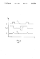
- FIG. 2 is a diagramatic representation of waveforms of signals appearing in the device of FIG. 1.
- an automatic device for enabling the frequency fh in the horizontal deflection of multi-synchronization monitors, not shown because conventional, to be changed.
- the device 1 is particularly, but not exclusively, intended for operation within a broad range of frequencies extending from 10 kHz to 100 kHz.
- This device 1 comprises an integrated circuit 2 incorporating a circuit portion 3 which is comprised of a frequency meter receiving a synchronization signal S1 at the frequency fh on one input.
- the meter 3 receives, on another input, a clock signal S2 derived, for example, from a high-accuracy crystal oscillator 4 outside the circuit 2.
- the meter 3 has a plurality n of outputs 5, each connected to a corresponding input 6 of a storage block 7 adapted to store the binary (n-bit) coding of signal S1 frequency value ph.
- the storage block 7 comprises a plurality n of outputs, shown at 8, which are connected to the input side of a counter 9.
- the counter 9 has an input 10 which receives a clock signal S3 supplied from the output 11 of a voltage-controlled oscillator VCO.
- the oscillation frequency of that device 12 is depending on the value of a control voltage Vc applied to an input 13.
- the structure of the integrated circuit 2 further comprises a phase comparator 14 which receives the signal S1 on one input 15. Another input 16 of that comparator 14 is directly connected to an output 21 of the counter 9 which is also a signal output for the circuit 2, producing a voltage value Vout plotted on curve 19 in FIG. 2.
- the phase comparator 14 produces, on an output 22, a Vc voltage signal S4 which is applied to the control input 13 of oscillator 12 through a filter 18 adapted to reduce the ripple present on the Vc voltage signal.
- the meter 3 takes a measurement of the frequency of the analog signal S1, while also performing an analog-to-digital conversion whereby the binary coding N for the value of the frequency fh is presented on the n inputs of the memory 7.
- the counter 9 Based on such coding and the value of signal S3 supplied by the oscillator 12, the counter 9 outputs an analog signal whose frequency is the same as that of signal S3 divided by the value N.
- This device 1 can effect a so-called latching of the frequency to the variation of signal S1.
- the frequency meter 3 is able to measure the value of pf with an approximation of plus/minus 1%. Thus, if the frequency fh undergoes a variation below this small range, the meter 3 may be unable to detect such a variation. In that event, however, the value of the coding N stored in block 7 would still remain unchanged, and the oscillator 12 would alter the value of its own operating frequency so as to allow fh to be latched.
- the device 1 of this invention allows of automatic tuning of the oscillator 12 within a broad range of frequencies fh of the input signal S1. This is ensured by that the counter 9, as suitably programmed, makes the frequencies of the oscillator 12 comparable to those of the input synchronizations ph.
- the integrated circuit embodying this invention has shown to be peculiarly fast in effecting the frequency latch, thereby greatly enhancing the performances of discrete components made in accordance with the prior art.
Landscapes
- Engineering & Computer Science (AREA)
- Theoretical Computer Science (AREA)
- Physics & Mathematics (AREA)
- General Physics & Mathematics (AREA)
- Radar, Positioning & Navigation (AREA)
- Remote Sensing (AREA)
- Computer Hardware Design (AREA)
- Human Computer Interaction (AREA)
- General Engineering & Computer Science (AREA)
- Stabilization Of Oscillater, Synchronisation, Frequency Synthesizers (AREA)
- Details Of Television Scanning (AREA)
- Synchronizing For Television (AREA)
Priority Applications (1)
| Application Number | Priority Date | Filing Date | Title |
|---|---|---|---|
| US08/296,205 USRE35588E (en) | 1990-06-27 | 1994-08-25 | Broad operational range, automatic device for the change of frequency in the horizontal deflection of multi-synchronization monitors |
Applications Claiming Priority (2)
| Application Number | Priority Date | Filing Date | Title |
|---|---|---|---|
| IT20784A/90 | 1990-06-27 | ||
| IT02078490A IT1251352B (it) | 1990-06-27 | 1990-06-27 | Dispositivo automatico ad ampio spettro operativo per il cambio di frequenza nella deflessione orizzontale di monitor a multisincronismo |
Related Child Applications (1)
| Application Number | Title | Priority Date | Filing Date |
|---|---|---|---|
| US08/296,205 Reissue USRE35588E (en) | 1990-06-27 | 1994-08-25 | Broad operational range, automatic device for the change of frequency in the horizontal deflection of multi-synchronization monitors |
Publications (1)
| Publication Number | Publication Date |
|---|---|
| US5142204A true US5142204A (en) | 1992-08-25 |
Family
ID=11172024
Family Applications (2)
| Application Number | Title | Priority Date | Filing Date |
|---|---|---|---|
| US07/713,691 Ceased US5142204A (en) | 1990-06-27 | 1991-06-11 | Broad operational range, automatic device for the change of frequency in the horizontal deflection of multi-synchronization monitors |
| US08/296,205 Expired - Lifetime USRE35588E (en) | 1990-06-27 | 1994-08-25 | Broad operational range, automatic device for the change of frequency in the horizontal deflection of multi-synchronization monitors |
Family Applications After (1)
| Application Number | Title | Priority Date | Filing Date |
|---|---|---|---|
| US08/296,205 Expired - Lifetime USRE35588E (en) | 1990-06-27 | 1994-08-25 | Broad operational range, automatic device for the change of frequency in the horizontal deflection of multi-synchronization monitors |
Country Status (7)
| Country | Link |
|---|---|
| US (2) | US5142204A (de) |
| EP (1) | EP0463418B1 (de) |
| JP (1) | JP3095813B2 (de) |
| KR (1) | KR920001314A (de) |
| DE (1) | DE69129880T2 (de) |
| IT (1) | IT1251352B (de) |
| TW (1) | TW209928B (de) |
Cited By (6)
| Publication number | Priority date | Publication date | Assignee | Title |
|---|---|---|---|---|
| EP0599084A1 (de) * | 1992-11-23 | 1994-06-01 | Eastman Kodak Company | Schaltung zur Abtrennung des Synchronisationssignals |
| US5764302A (en) * | 1995-09-18 | 1998-06-09 | Intelpros | Automatic picture-adjusting apparatus of video appliance and method thereof |
| US5917552A (en) * | 1996-03-29 | 1999-06-29 | Pixelvision Technology, Inc. | Video signal interface system utilizing deductive control |
| US6097440A (en) * | 1995-11-17 | 2000-08-01 | Sony Corporation | Synchronous processing device |
| JP3095813B2 (ja) | 1990-06-27 | 2000-10-10 | エスティーマイクロエレクトロニクスエス.アール.エル. | マルチ同期モニターの水平偏向周波数を可変にするための広動作帯域の自動デバイス |
| US20120249863A1 (en) * | 2011-03-31 | 2012-10-04 | Flir Systems, Inc. | Boresight alignment station |
Families Citing this family (1)
| Publication number | Priority date | Publication date | Assignee | Title |
|---|---|---|---|---|
| US6876358B2 (en) * | 2001-12-25 | 2005-04-05 | Nec-Mitsubishi Electric Visual Systems Corporation | Multi-sync display apparatus |
Citations (2)
| Publication number | Priority date | Publication date | Assignee | Title |
|---|---|---|---|---|
| US4827341A (en) * | 1986-12-16 | 1989-05-02 | Fuji Photo Equipment Co., Ltd. | Synchronizing signal generating circuit |
| US5043813A (en) * | 1990-03-26 | 1991-08-27 | Thomson Consumer Electronics, Inc. | Display locked timing signals for video processing |
Family Cites Families (20)
| Publication number | Priority date | Publication date | Assignee | Title |
|---|---|---|---|---|
| US3753142A (en) * | 1972-06-12 | 1973-08-14 | Logimetrics Inc | Signal generators employing digital phase locked loops and compensating circuits |
| JPS5360150A (en) * | 1976-11-10 | 1978-05-30 | Fujitsu Ltd | Instantaneous leading-in system for digital phase lock loop |
| US4242639A (en) * | 1978-09-05 | 1980-12-30 | Ncr Corporation | Digital phase lock circuit |
| DE2940482C2 (de) * | 1979-10-05 | 1982-03-04 | Siemens AG, 1000 Berlin und 8000 München | Einstellbarer Frequenzgenerator |
| US4462110A (en) * | 1981-04-07 | 1984-07-24 | Honeywell Information Systems Inc. | Digital phase-locked loop |
| US4399459A (en) * | 1981-10-30 | 1983-08-16 | Nicolet Instrument Corporation | Flexible video synchronization circuit |
| DE3216631C2 (de) * | 1982-05-04 | 1984-07-12 | Siemens AG, 1000 Berlin und 8000 München | Oszillatorschaltung |
| JPS59212891A (ja) * | 1983-05-18 | 1984-12-01 | パイオニア株式会社 | 同期回路 |
| US4617520A (en) * | 1984-01-03 | 1986-10-14 | Motorola, Inc. | Digital lock detector for a phase-locked loop |
| US4577163A (en) * | 1984-07-09 | 1986-03-18 | Honeywell Inc. | Digital phase locked loop |
| US4680780A (en) * | 1986-05-01 | 1987-07-14 | Tektronix, Inc. | Clock recovery digital phase-locked loop |
| JPS6315530A (ja) * | 1986-07-08 | 1988-01-22 | Sumitomo Electric Ind Ltd | デイジタル位相同期ル−プ |
| US4689582A (en) * | 1986-10-27 | 1987-08-25 | Rca Corporation | Phase-lock-loop circuit for a television apparatus |
| DE3708538A1 (de) * | 1987-03-13 | 1988-09-22 | Siemens Ag | Oszillatorschaltung |
| US4820993A (en) * | 1987-08-17 | 1989-04-11 | Cyclotomics, Inc. | Digital phase lock loop |
| EP0310088B1 (de) * | 1987-10-01 | 1996-06-05 | Sharp Kabushiki Kaisha | Digitale Phasenregelschleifen-Anordnung |
| US5193103A (en) * | 1988-03-02 | 1993-03-09 | Gec - Marconi Limited | Digital phase locked loop circuit |
| JPH07101847B2 (ja) * | 1988-10-21 | 1995-11-01 | シャープ株式会社 | デジタルフェイズロックドループ装置 |
| US4965533A (en) * | 1989-08-31 | 1990-10-23 | Qualcomm, Inc. | Direct digital synthesizer driven phase lock loop frequency synthesizer |
| IT1251352B (it) * | 1990-06-27 | 1995-05-08 | St Microelectronics Srl | Dispositivo automatico ad ampio spettro operativo per il cambio di frequenza nella deflessione orizzontale di monitor a multisincronismo |
-
1990
- 1990-06-27 IT IT02078490A patent/IT1251352B/it active IP Right Grant
-
1991
- 1991-06-05 EP EP91109162A patent/EP0463418B1/de not_active Expired - Lifetime
- 1991-06-05 DE DE69129880T patent/DE69129880T2/de not_active Expired - Fee Related
- 1991-06-11 US US07/713,691 patent/US5142204A/en not_active Ceased
- 1991-06-24 KR KR1019910010464A patent/KR920001314A/ko not_active Withdrawn
- 1991-06-26 JP JP03180608A patent/JP3095813B2/ja not_active Expired - Fee Related
- 1991-07-29 TW TW080105901A patent/TW209928B/zh active
-
1994
- 1994-08-25 US US08/296,205 patent/USRE35588E/en not_active Expired - Lifetime
Patent Citations (2)
| Publication number | Priority date | Publication date | Assignee | Title |
|---|---|---|---|---|
| US4827341A (en) * | 1986-12-16 | 1989-05-02 | Fuji Photo Equipment Co., Ltd. | Synchronizing signal generating circuit |
| US5043813A (en) * | 1990-03-26 | 1991-08-27 | Thomson Consumer Electronics, Inc. | Display locked timing signals for video processing |
Cited By (7)
| Publication number | Priority date | Publication date | Assignee | Title |
|---|---|---|---|---|
| JP3095813B2 (ja) | 1990-06-27 | 2000-10-10 | エスティーマイクロエレクトロニクスエス.アール.エル. | マルチ同期モニターの水平偏向周波数を可変にするための広動作帯域の自動デバイス |
| EP0599084A1 (de) * | 1992-11-23 | 1994-06-01 | Eastman Kodak Company | Schaltung zur Abtrennung des Synchronisationssignals |
| US5764302A (en) * | 1995-09-18 | 1998-06-09 | Intelpros | Automatic picture-adjusting apparatus of video appliance and method thereof |
| US6097440A (en) * | 1995-11-17 | 2000-08-01 | Sony Corporation | Synchronous processing device |
| US5917552A (en) * | 1996-03-29 | 1999-06-29 | Pixelvision Technology, Inc. | Video signal interface system utilizing deductive control |
| US20120249863A1 (en) * | 2011-03-31 | 2012-10-04 | Flir Systems, Inc. | Boresight alignment station |
| US8860800B2 (en) * | 2011-03-31 | 2014-10-14 | Flir Systems, Inc. | Boresight alignment station |
Also Published As
| Publication number | Publication date |
|---|---|
| EP0463418B1 (de) | 1998-07-29 |
| IT9020784A1 (it) | 1991-12-27 |
| IT9020784A0 (it) | 1990-06-27 |
| KR920001314A (ko) | 1992-01-30 |
| DE69129880T2 (de) | 1999-04-15 |
| IT1251352B (it) | 1995-05-08 |
| TW209928B (de) | 1993-07-21 |
| EP0463418A3 (en) | 1992-04-29 |
| JP3095813B2 (ja) | 2000-10-10 |
| JPH04233586A (ja) | 1992-08-21 |
| DE69129880D1 (de) | 1998-09-03 |
| EP0463418A2 (de) | 1992-01-02 |
| USRE35588E (en) | 1997-08-19 |
Similar Documents
| Publication | Publication Date | Title |
|---|---|---|
| US5424687A (en) | PLL frequency synthesizer and PLL frequency synthesizing method capable of obtaining high-speed lock-up and highly-reliable oscillation | |
| US5694089A (en) | Fast frequency switching synthesizer | |
| US6510191B2 (en) | Direct digital synthesizer based on delay line with sorted taps | |
| JP3747480B2 (ja) | 周波数シンセサイザ | |
| EP0218406A2 (de) | Schaltung zur Erzeugung eines Abtasttaktes | |
| JP3324401B2 (ja) | Pll回路 | |
| US5304954A (en) | PLL synthesizer having frequency dividers with reset control | |
| US6005420A (en) | Frequency multiplying circuit having a greater multiplying ratio | |
| CA2125443C (en) | Digitally controlled fractional frequency synthesizer | |
| KR0138220B1 (ko) | 위상동기루프회로의 클럭지연보상 및 듀티제어 장치 | |
| US4849714A (en) | Signal generating apparatus | |
| JP2806239B2 (ja) | 周波数シンセサイザ | |
| US5142204A (en) | Broad operational range, automatic device for the change of frequency in the horizontal deflection of multi-synchronization monitors | |
| US5153526A (en) | Numerical control type oscillator apparatus | |
| US5574515A (en) | Voltage controlled oscillator circuit and automatic fine tuning circuit for TV | |
| US20020012412A1 (en) | Phase lock loop circuit | |
| US5089793A (en) | Semiconductor device having an oscillatory circuit | |
| CN116647234A (zh) | 一种锁相环电路、芯片以及模组设备 | |
| JPH1070457A (ja) | Pll回路 | |
| KR0141689B1 (ko) | 고속 pll 주파수 합성회로 | |
| JP2827389B2 (ja) | Pll用半導体集積回路 | |
| JPH06209216A (ja) | 信号発生装置 | |
| JPH1188156A (ja) | クロック生成用pll回路 | |
| JPH0823274A (ja) | Pll周波数シンセサイザ | |
| JPH01114122A (ja) | デジタル周波数シンセサイザ |
Legal Events
| Date | Code | Title | Description |
|---|---|---|---|
| AS | Assignment |
Owner name: SGS-THOMSON MICROELECTRONICS S.R.L., ITALY Free format text: ASSIGNMENT OF ASSIGNORS INTEREST.;ASSIGNORS:GORNATI, SILVANO;MERLO, MAURO;ZUFFADA, MAURIZIO;AND OTHERS;REEL/FRAME:005798/0056 Effective date: 19910617 |
|
| STCF | Information on status: patent grant |
Free format text: PATENTED CASE |
|
| RF | Reissue application filed |
Effective date: 19940825 |
|
| FPAY | Fee payment |
Year of fee payment: 4 |
|
| FEPP | Fee payment procedure |
Free format text: PAYOR NUMBER ASSIGNED (ORIGINAL EVENT CODE: ASPN); ENTITY STATUS OF PATENT OWNER: LARGE ENTITY |