US5152312A - Automatic shuttle valve - Google Patents
Automatic shuttle valve Download PDFInfo
- Publication number
- US5152312A US5152312A US07/741,679 US74167991A US5152312A US 5152312 A US5152312 A US 5152312A US 74167991 A US74167991 A US 74167991A US 5152312 A US5152312 A US 5152312A
- Authority
- US
- United States
- Prior art keywords
- fitting
- driven mechanism
- piston
- hydraulic fluid
- conduit
- Prior art date
- Legal status (The legal status is an assumption and is not a legal conclusion. Google has not performed a legal analysis and makes no representation as to the accuracy of the status listed.)
- Expired - Lifetime
Links
Images

Classifications
-
- F—MECHANICAL ENGINEERING; LIGHTING; HEATING; WEAPONS; BLASTING
- F15—FLUID-PRESSURE ACTUATORS; HYDRAULICS OR PNEUMATICS IN GENERAL
- F15B—SYSTEMS ACTING BY MEANS OF FLUIDS IN GENERAL; FLUID-PRESSURE ACTUATORS, e.g. SERVOMOTORS; DETAILS OF FLUID-PRESSURE SYSTEMS, NOT OTHERWISE PROVIDED FOR
- F15B13/00—Details of servomotor systems ; Valves for servomotor systems
- F15B13/02—Fluid distribution or supply devices characterised by their adaptation to the control of servomotors
- F15B13/022—Flow-dividers; Priority valves
-
- Y—GENERAL TAGGING OF NEW TECHNOLOGICAL DEVELOPMENTS; GENERAL TAGGING OF CROSS-SECTIONAL TECHNOLOGIES SPANNING OVER SEVERAL SECTIONS OF THE IPC; TECHNICAL SUBJECTS COVERED BY FORMER USPC CROSS-REFERENCE ART COLLECTIONS [XRACs] AND DIGESTS
- Y10—TECHNICAL SUBJECTS COVERED BY FORMER USPC
- Y10T—TECHNICAL SUBJECTS COVERED BY FORMER US CLASSIFICATION
- Y10T137/00—Fluid handling
- Y10T137/2496—Self-proportioning or correlating systems
- Y10T137/2559—Self-controlled branched flow systems
- Y10T137/265—Plural outflows
- Y10T137/2655—Biased open isolation valve
Definitions
- the invention concerns an automatic shuttle valve with a piston that slides back and forth in a bore that extends through a housing, distributing hydraulic fluid from a driving mechanism among at least two driven mechanisms in accordance with how much power each is demanding.
- the applicant is presently distributing metal, or the like material, plate and strip tearing and prying type rescue equipment under the trademark "Lukas".
- This rescue equipment may be employed to extract passengers from a wrecked vehicle with jammed doors.
- One driven mechanism makes an incision in the plate material of the body of the wrecked vehicle. If the incision is not wide enough to remove the victims from the vehicle, another driven mechanism expands the opening. There is often not enough time in an emergency situation to uncouple the incision cutter from the driving mechanism and to attach the expander. It would accordingly be desirable to have both tools mounted and ready at the same time. To operate both mechanisms alternately or simultaneously off the same driving mechanism, however, has always required manual switching from the driving mechanism.
- the object of the present invention is accordingly to simplify an automatic shuttle valve to the extent that it will be less expensive to manufacture and that fewer parts will need to be kept in stock.
- a rounded cross section conically shaped block at each end of the shiftable piston can engage a correspondingly profiled seat in a high pressure fitting and seal off the respective end of the bore.
- the piston also has a central position at which both fittings are not sealed. Because the driving mechanism communicates with the driven mechanisms through hydraulic fluid-conveyance branches, this ensures that any driven mechanism that is being operated will be supplied with power and that any driven mechanism that is not being operated will be deprived of power due to one or more of the seats respectively opening or closing.
- the branches may accommodate throttles of a known design that regulate the flow and eliminate surges.
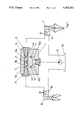
- FIG. 1 shows the valve at rest
- FIG. 2 shows the valve with one driven mechanism in operation.
- a driving mechanism 9 supplies power to two driven mechanisms 7 and 8 in accordance with how much each driven mechanism demands in a way that will now be described.
- Each driven mechanism 7 and 8 is activated by a respective manual diversion valve 7a and 8a.
- Driving mechanism 9 obtains hydraulic fluid from a reservoir 13 and supplies it under pressure to one or both of the hydraulic fluid delivery branch conduits 10a and 10b, which deliver the fluid to the opposite ends of an automatic shuttle valve that distributes the fluid through respective manually operable valves 7a and 8a, to either of the driven mechanisms 7 and 8 or directly back to reservoir 13, depending upon the state of the manual valves.
- the automatic shuttle valve has a housing 1 and a piston 3 that slides back and forth in a bore 2 extending through the housing 1.
- a circular cross section, conical end part block 4a and 4b at each end of the piston 3 can engage a respective seat 5c and 6c in a respective fitting 5 and 6 and block off communication between that fitting and the associated hydraulic fluid conduit 10a and 10b leading from the common driving mechanism 9.
- the conduits 10a and 10b meet the bore 3 inward of the respective seats 5c and 6c.
- the fittings 5 and 6 are inserted in respective ends of the otherwise open ended bore.
- Each fitting 5 and 6 opens into a respective hydraulic fluid line that leads to one of the driven mechanisms.
- block 4a can engage seat 5c in fitting 5.
- the seat 5c is shaped, sized and inclined to the cone angle of the block 4a. Their engagement blocks off communication of the fitting 5 with the branch conduit 10a and with the driven mechanism fluid conduit to the respective driven mechanism 7 or 8.
- block 4b can engage seat 6c in fitting 6, blocking off communication of the fitting 6 with the branch conduit 10b and with the driven mechanism fluid conduit to the respective driven mechanism 7 or 8.
- both manual valves are thrown to an operating position, and the piston 3 remains at the neutral mid position illustrated in FIG. 1, with fluid distributed equally to both of the driven mechanisms 7 and 8.
- throttles 11 and 12 can be accommodated in the branches 10a and 10b, respectively.
Landscapes
- Engineering & Computer Science (AREA)
- Physics & Mathematics (AREA)
- Fluid Mechanics (AREA)
- Mechanical Engineering (AREA)
- General Engineering & Computer Science (AREA)
- Fluid-Pressure Circuits (AREA)
- Servomotors (AREA)
- Control Of Eletrric Generators (AREA)
- Fluid-Driven Valves (AREA)
- Multiple-Way Valves (AREA)
Applications Claiming Priority (2)
| Application Number | Priority Date | Filing Date | Title |
|---|---|---|---|
| EP19900117151 EP0473827B1 (de) | 1990-09-06 | 1990-09-06 | Automatisches Wechselventil |
| EP90117151 | 1990-09-06 |
Publications (1)
| Publication Number | Publication Date |
|---|---|
| US5152312A true US5152312A (en) | 1992-10-06 |
Family
ID=8204438
Family Applications (1)
| Application Number | Title | Priority Date | Filing Date |
|---|---|---|---|
| US07/741,679 Expired - Lifetime US5152312A (en) | 1990-09-06 | 1991-08-07 | Automatic shuttle valve |
Country Status (6)
| Country | Link |
|---|---|
| US (1) | US5152312A (de) |
| EP (1) | EP0473827B1 (de) |
| JP (1) | JPH05202907A (de) |
| AT (1) | ATE130911T1 (de) |
| DE (1) | DE59009927D1 (de) |
| ES (1) | ES2080091T3 (de) |
Cited By (5)
| Publication number | Priority date | Publication date | Assignee | Title |
|---|---|---|---|---|
| US20060081120A1 (en) * | 2004-10-20 | 2006-04-20 | Lukas Hydraulik Gmbh | Control device |
| US8132588B1 (en) | 2008-07-02 | 2012-03-13 | Hydro-Gear Limited Partnership | Valve |
| US20170234442A1 (en) * | 2010-05-26 | 2017-08-17 | Petrolvalves S.R.L. | Intelligent Pressure Relief Device For A Double Isolation Valve |
| US9862137B2 (en) | 2015-04-20 | 2018-01-09 | Milwaukee Electric Tool Corporation | PEX expanding tool |
| US10000007B2 (en) | 2015-06-10 | 2018-06-19 | Milwaukee Electric Tool Corporation | PEX expanding tool |
Citations (17)
| Publication number | Priority date | Publication date | Assignee | Title |
|---|---|---|---|---|
| GB527958A (en) * | 1939-04-24 | 1940-10-18 | Edward Kinsella | Improvements in or relating to the distribution of fluids |
| US2799996A (en) * | 1954-06-07 | 1957-07-23 | Vickers Inc | Single pump, plural motor power transmission |
| US2956577A (en) * | 1956-11-16 | 1960-10-18 | New York Air Brake Co | Valve |
| US2971522A (en) * | 1957-09-20 | 1961-02-14 | Bendix Corp | Flow proportioning valve |
| US3323533A (en) * | 1964-11-09 | 1967-06-06 | Cessna Aircraft Co | Combination proportional and priority flow divider |
| US3348563A (en) * | 1965-02-03 | 1967-10-24 | Caterpillar Tractor Co | Flow divider valve |
| GB1101903A (en) * | 1965-04-15 | 1968-02-07 | Daimler Benz Ag | Improvements in control valve arrangements in pressure fluid power installations |
| US3455210A (en) * | 1966-10-26 | 1969-07-15 | Eaton Yale & Towne | Adjustable,metered,directional flow control arrangement |
| FR2076856A5 (de) * | 1970-01-30 | 1971-10-15 | Jurkovic Dimitrij | |
| US3674047A (en) * | 1970-09-04 | 1972-07-04 | Mikhail Borisovich Tauger | Throttle divider of fluid medium flow |
| FR2134054A2 (de) * | 1971-04-22 | 1972-12-01 | Bosch | |
| FR2155545A5 (de) * | 1971-10-02 | 1973-05-18 | Fichtel & Sachs Ag | |
| DE2440498A1 (de) * | 1973-09-03 | 1975-03-13 | Islay Duncan Campbell | Hydraulisches steuerventil |
| US3982469A (en) * | 1976-01-23 | 1976-09-28 | Caterpillar Tractor Co. | Apparatus for controlling work element operating pressures in a fluid system |
| DE3142352A1 (de) * | 1981-02-11 | 1982-09-09 | Hydraulika GmbH, 7800 Freiburg | Gleichlaufventil |
| DE8702770U1 (de) * | 1987-02-24 | 1987-04-02 | Esser, Wilhelm, 4320 Hattingen | Hydraulisches Wechselventil |
| US4655250A (en) * | 1986-02-03 | 1987-04-07 | The Cessna Aircraft Company | Open center unloading valve |
Family Cites Families (2)
| Publication number | Priority date | Publication date | Assignee | Title |
|---|---|---|---|---|
| JPS4415135Y1 (de) * | 1964-05-22 | 1969-06-30 | ||
| JPS5620809A (en) * | 1979-07-27 | 1981-02-26 | Daikin Ind Ltd | Fluid control system |
-
1990
- 1990-09-06 DE DE59009927T patent/DE59009927D1/de not_active Expired - Lifetime
- 1990-09-06 ES ES90117151T patent/ES2080091T3/es not_active Expired - Lifetime
- 1990-09-06 AT AT90117151T patent/ATE130911T1/de not_active IP Right Cessation
- 1990-09-06 EP EP19900117151 patent/EP0473827B1/de not_active Expired - Lifetime
-
1991
- 1991-08-07 US US07/741,679 patent/US5152312A/en not_active Expired - Lifetime
- 1991-08-09 JP JP28536691A patent/JPH05202907A/ja active Pending
Patent Citations (17)
| Publication number | Priority date | Publication date | Assignee | Title |
|---|---|---|---|---|
| GB527958A (en) * | 1939-04-24 | 1940-10-18 | Edward Kinsella | Improvements in or relating to the distribution of fluids |
| US2799996A (en) * | 1954-06-07 | 1957-07-23 | Vickers Inc | Single pump, plural motor power transmission |
| US2956577A (en) * | 1956-11-16 | 1960-10-18 | New York Air Brake Co | Valve |
| US2971522A (en) * | 1957-09-20 | 1961-02-14 | Bendix Corp | Flow proportioning valve |
| US3323533A (en) * | 1964-11-09 | 1967-06-06 | Cessna Aircraft Co | Combination proportional and priority flow divider |
| US3348563A (en) * | 1965-02-03 | 1967-10-24 | Caterpillar Tractor Co | Flow divider valve |
| GB1101903A (en) * | 1965-04-15 | 1968-02-07 | Daimler Benz Ag | Improvements in control valve arrangements in pressure fluid power installations |
| US3455210A (en) * | 1966-10-26 | 1969-07-15 | Eaton Yale & Towne | Adjustable,metered,directional flow control arrangement |
| FR2076856A5 (de) * | 1970-01-30 | 1971-10-15 | Jurkovic Dimitrij | |
| US3674047A (en) * | 1970-09-04 | 1972-07-04 | Mikhail Borisovich Tauger | Throttle divider of fluid medium flow |
| FR2134054A2 (de) * | 1971-04-22 | 1972-12-01 | Bosch | |
| FR2155545A5 (de) * | 1971-10-02 | 1973-05-18 | Fichtel & Sachs Ag | |
| DE2440498A1 (de) * | 1973-09-03 | 1975-03-13 | Islay Duncan Campbell | Hydraulisches steuerventil |
| US3982469A (en) * | 1976-01-23 | 1976-09-28 | Caterpillar Tractor Co. | Apparatus for controlling work element operating pressures in a fluid system |
| DE3142352A1 (de) * | 1981-02-11 | 1982-09-09 | Hydraulika GmbH, 7800 Freiburg | Gleichlaufventil |
| US4655250A (en) * | 1986-02-03 | 1987-04-07 | The Cessna Aircraft Company | Open center unloading valve |
| DE8702770U1 (de) * | 1987-02-24 | 1987-04-02 | Esser, Wilhelm, 4320 Hattingen | Hydraulisches Wechselventil |
Cited By (13)
| Publication number | Priority date | Publication date | Assignee | Title |
|---|---|---|---|---|
| US20060081120A1 (en) * | 2004-10-20 | 2006-04-20 | Lukas Hydraulik Gmbh | Control device |
| US7409828B2 (en) * | 2004-10-20 | 2008-08-12 | Lukas Hydraulik Gmbh | Control device |
| US8132588B1 (en) | 2008-07-02 | 2012-03-13 | Hydro-Gear Limited Partnership | Valve |
| US9410631B1 (en) | 2008-07-02 | 2016-08-09 | Hydro-Gear Limited Partnership | Valve |
| US9976663B2 (en) * | 2010-05-26 | 2018-05-22 | Petrolvalves S.P.A. | Intelligent pressure relief device for a double isolation valve |
| US20170234442A1 (en) * | 2010-05-26 | 2017-08-17 | Petrolvalves S.R.L. | Intelligent Pressure Relief Device For A Double Isolation Valve |
| US9862137B2 (en) | 2015-04-20 | 2018-01-09 | Milwaukee Electric Tool Corporation | PEX expanding tool |
| US9993961B2 (en) | 2015-04-20 | 2018-06-12 | Milwaukee Electric Tool Corporation | PEX expanding tool |
| US10926451B2 (en) | 2015-04-20 | 2021-02-23 | Milwaukee Electric Tool Corporation | PEX expanding tool |
| US11648727B2 (en) | 2015-04-20 | 2023-05-16 | Milwaukee Electric Tool Corporation | PEX expanding tool |
| US12023849B2 (en) | 2015-04-20 | 2024-07-02 | Milwaukee Electric Tool Corporation | PEX expanding tool |
| US10000007B2 (en) | 2015-06-10 | 2018-06-19 | Milwaukee Electric Tool Corporation | PEX expanding tool |
| US10946576B2 (en) | 2015-06-10 | 2021-03-16 | Milwaukee Electric Tool Corporation | PEX expanding tool |
Also Published As
| Publication number | Publication date |
|---|---|
| EP0473827B1 (de) | 1995-11-29 |
| ATE130911T1 (de) | 1995-12-15 |
| JPH05202907A (ja) | 1993-08-10 |
| DE59009927D1 (de) | 1996-01-11 |
| EP0473827A1 (de) | 1992-03-11 |
| ES2080091T3 (es) | 1996-02-01 |
Similar Documents
| Publication | Publication Date | Title |
|---|---|---|
| JP5762744B2 (ja) | 複動形流体流れ方向制御弁 | |
| US3878864A (en) | Bypass valve | |
| CA2120052C (en) | Hydraulic system for open or closed-centered systems | |
| CA2005587C (en) | Balanced servo-operated multiway valve | |
| DE2748079C2 (de) | Wasserdruck-Verstärkungsanlage | |
| US2392421A (en) | Hydraulic control valve | |
| EP0845397A2 (de) | Druckregelvorrichtung für elektropneumatische Bremsanlagen von Fahrzeugen, insbesondere Nutzfahrzeugen | |
| US4576416A (en) | Multi-circuit pressure medium brake system | |
| US5263679A (en) | Valve with actuator | |
| US6422127B1 (en) | Hydraulic actuation arrangement | |
| KR960023846A (ko) | 유압 제어 시스템 | |
| US5152312A (en) | Automatic shuttle valve | |
| EP1258663A3 (de) | Hydraulisches Ventilsystem | |
| JPS59500730A (ja) | 制御装置 | |
| US5209261A (en) | Slide valve | |
| US5469703A (en) | Device for controlling a hydraulic motor | |
| US6364280B1 (en) | Adjustable slow shift control unit | |
| US4748896A (en) | Safety valve assembly | |
| JPH01112001A (ja) | 自動車における双圧圧力発生装置 | |
| EP1629156A1 (de) | Hydraulische steueranordnung | |
| JPH0316869A (ja) | ブレーキ弁装置 | |
| US5749225A (en) | Hydraulic systems and valve assemblies | |
| US4653811A (en) | Relay valve device | |
| US5758683A (en) | On/off circuit for a hydraulic system | |
| US5044399A (en) | Switch valve |
Legal Events
| Date | Code | Title | Description |
|---|---|---|---|
| AS | Assignment |
Owner name: FAG KUGELFISCHEER GEORG SCHAFER, KOMANDIGESELLSCHA Free format text: ASSIGNMENT OF ASSIGNORS INTEREST.;ASSIGNOR:KOGEL, KARL;REEL/FRAME:005804/0720 Effective date: 19910719 |
|
| STCF | Information on status: patent grant |
Free format text: PATENTED CASE |
|
| AS | Assignment |
Owner name: LUKAS HYDRAULIK GMBH, GERMANY Free format text: ASSIGNMENT OF ASSIGNORS INTEREST;ASSIGNOR:FAG KUGELFISCHER GEORG SCHAFER KGAA;REEL/FRAME:006867/0612 Effective date: 19940209 |
|
| FEPP | Fee payment procedure |
Free format text: PAT HOLDER CLAIMS SMALL ENTITY STATUS - SMALL BUSINESS (ORIGINAL EVENT CODE: SM02); ENTITY STATUS OF PATENT OWNER: LARGE ENTITY Free format text: PAYOR NUMBER ASSIGNED (ORIGINAL EVENT CODE: ASPN); ENTITY STATUS OF PATENT OWNER: LARGE ENTITY |
|
| FPAY | Fee payment |
Year of fee payment: 4 |
|
| AS | Assignment |
Owner name: LUKAS HYDRAULIK GMBH & CO. K.G., GERMANY Free format text: CHANGE OF NAME;ASSIGNOR:LUKAS HYDRAULIK GMBH;REEL/FRAME:008975/0667 Effective date: 19961210 |
|
| FPAY | Fee payment |
Year of fee payment: 8 |
|
| FEPP | Fee payment procedure |
Free format text: PAT HOLDER NO LONGER CLAIMS SMALL ENTITY STATUS, ENTITY STATUS SET TO UNDISCOUNTED (ORIGINAL EVENT CODE: STOL); ENTITY STATUS OF PATENT OWNER: LARGE ENTITY |
|
| REFU | Refund |
Free format text: REFUND - 11.5 YR SURCHARGE- LATE PMT W/IN 6 MO, SMALL ENTITY (ORIGINAL EVENT CODE: R2556); ENTITY STATUS OF PATENT OWNER: LARGE ENTITY Free format text: REFUND - PAYMENT OF MAINTENANCE FEE, 12TH YR, SMALL ENTITY (ORIGINAL EVENT CODE: R2553); ENTITY STATUS OF PATENT OWNER: LARGE ENTITY |
|
| REMI | Maintenance fee reminder mailed | ||
| FPAY | Fee payment |
Year of fee payment: 12 |
|
| SULP | Surcharge for late payment |
Year of fee payment: 11 |
|
| FEPP | Fee payment procedure |
Free format text: ENTITY STATUS SET TO UNDISCOUNTED (ORIGINAL EVENT CODE: BIG.); ENTITY STATUS OF PATENT OWNER: LARGE ENTITY |
|
| AS | Assignment |
Owner name: LUKAS HYDRAULIK GMBH,GERMANY Free format text: CHANGE OF NAME;ASSIGNOR:LUKAS HYDRAULIK GMBH & CO. KG;REEL/FRAME:024202/0009 Effective date: 20020625 |