US5154944A - Method and apparatus for developing a latent magnetic image - Google Patents
Method and apparatus for developing a latent magnetic image Download PDFInfo
- Publication number
- US5154944A US5154944A US07/789,325 US78932591A US5154944A US 5154944 A US5154944 A US 5154944A US 78932591 A US78932591 A US 78932591A US 5154944 A US5154944 A US 5154944A
- Authority
- US
- United States
- Prior art keywords
- image
- toner
- recording medium
- powder
- image recording
- Prior art date
- Legal status (The legal status is an assumption and is not a legal conclusion. Google has not performed a legal analysis and makes no representation as to the accuracy of the status listed.)
- Expired - Fee Related
Links
- 238000000034 method Methods 0.000 title claims abstract description 31
- 239000000843 powder Substances 0.000 claims abstract description 62
- 239000002245 particle Substances 0.000 claims description 18
- 239000000463 material Substances 0.000 claims description 13
- 229920005989 resin Polymers 0.000 claims description 9
- 239000011347 resin Substances 0.000 claims description 9
- 238000012546 transfer Methods 0.000 claims description 6
- 239000004020 conductor Substances 0.000 claims description 5
- XEEYBQQBJWHFJM-UHFFFAOYSA-N Iron Chemical group [Fe] XEEYBQQBJWHFJM-UHFFFAOYSA-N 0.000 description 9
- 238000011161 development Methods 0.000 description 7
- OKTJSMMVPCPJKN-UHFFFAOYSA-N Carbon Chemical compound [C] OKTJSMMVPCPJKN-UHFFFAOYSA-N 0.000 description 6
- 229910052799 carbon Inorganic materials 0.000 description 6
- 229920001225 polyester resin Polymers 0.000 description 5
- 239000004645 polyester resin Substances 0.000 description 5
- PXHVJJICTQNCMI-UHFFFAOYSA-N Nickel Chemical compound [Ni] PXHVJJICTQNCMI-UHFFFAOYSA-N 0.000 description 4
- 229910052742 iron Inorganic materials 0.000 description 4
- 239000000049 pigment Substances 0.000 description 4
- RYGMFSIKBFXOCR-UHFFFAOYSA-N Copper Chemical compound [Cu] RYGMFSIKBFXOCR-UHFFFAOYSA-N 0.000 description 3
- 239000011230 binding agent Substances 0.000 description 3
- 229910052802 copper Inorganic materials 0.000 description 3
- 239000010949 copper Substances 0.000 description 3
- 230000006698 induction Effects 0.000 description 3
- 150000002500 ions Chemical class 0.000 description 3
- 238000000926 separation method Methods 0.000 description 3
- 229910001369 Brass Inorganic materials 0.000 description 2
- VZCYOOQTPOCHFL-OWOJBTEDSA-N Fumaric acid Chemical compound OC(=O)\C=C\C(O)=O VZCYOOQTPOCHFL-OWOJBTEDSA-N 0.000 description 2
- OFOBLEOULBTSOW-UHFFFAOYSA-N Malonic acid Chemical compound OC(=O)CC(O)=O OFOBLEOULBTSOW-UHFFFAOYSA-N 0.000 description 2
- 229910052782 aluminium Inorganic materials 0.000 description 2
- XAGFODPZIPBFFR-UHFFFAOYSA-N aluminium Chemical compound [Al] XAGFODPZIPBFFR-UHFFFAOYSA-N 0.000 description 2
- IISBACLAFKSPIT-UHFFFAOYSA-N bisphenol A Chemical compound C=1C=C(O)C=CC=1C(C)(C)C1=CC=C(O)C=C1 IISBACLAFKSPIT-UHFFFAOYSA-N 0.000 description 2
- 239000010951 brass Substances 0.000 description 2
- 239000003795 chemical substances by application Substances 0.000 description 2
- 238000003384 imaging method Methods 0.000 description 2
- 239000000696 magnetic material Substances 0.000 description 2
- 238000005259 measurement Methods 0.000 description 2
- 229910052751 metal Inorganic materials 0.000 description 2
- 239000002184 metal Substances 0.000 description 2
- 229910052759 nickel Inorganic materials 0.000 description 2
- 229910052761 rare earth metal Inorganic materials 0.000 description 2
- 150000002910 rare earth metals Chemical class 0.000 description 2
- 238000012360 testing method Methods 0.000 description 2
- VZCYOOQTPOCHFL-UHFFFAOYSA-N trans-butenedioic acid Natural products OC(=O)C=CC(O)=O VZCYOOQTPOCHFL-UHFFFAOYSA-N 0.000 description 2
- 239000004793 Polystyrene Substances 0.000 description 1
- 239000004809 Teflon Substances 0.000 description 1
- 229920006362 Teflon® Polymers 0.000 description 1
- IGOJDKCIHXGPTI-UHFFFAOYSA-N [P].[Co].[Ni] Chemical compound [P].[Co].[Ni] IGOJDKCIHXGPTI-UHFFFAOYSA-N 0.000 description 1
- 229940090961 chromium dioxide Drugs 0.000 description 1
- IAQWMWUKBQPOIY-UHFFFAOYSA-N chromium(4+);oxygen(2-) Chemical compound [O-2].[O-2].[Cr+4] IAQWMWUKBQPOIY-UHFFFAOYSA-N 0.000 description 1
- AYTAKQFHWFYBMA-UHFFFAOYSA-N chromium(IV) oxide Inorganic materials O=[Cr]=O AYTAKQFHWFYBMA-UHFFFAOYSA-N 0.000 description 1
- 238000004140 cleaning Methods 0.000 description 1
- 229910017052 cobalt Inorganic materials 0.000 description 1
- 239000010941 cobalt Substances 0.000 description 1
- GUTLYIVDDKVIGB-UHFFFAOYSA-N cobalt atom Chemical compound [Co] GUTLYIVDDKVIGB-UHFFFAOYSA-N 0.000 description 1
- 238000010276 construction Methods 0.000 description 1
- 230000001419 dependent effect Effects 0.000 description 1
- 230000008021 deposition Effects 0.000 description 1
- 230000000694 effects Effects 0.000 description 1
- 239000003822 epoxy resin Substances 0.000 description 1
- 239000001530 fumaric acid Substances 0.000 description 1
- 238000010438 heat treatment Methods 0.000 description 1
- VZCYOOQTPOCHFL-UPHRSURJSA-N maleic acid Chemical compound OC(=O)\C=C/C(O)=O VZCYOOQTPOCHFL-UPHRSURJSA-N 0.000 description 1
- 239000011976 maleic acid Substances 0.000 description 1
- 230000007257 malfunction Effects 0.000 description 1
- WPBNNNQJVZRUHP-UHFFFAOYSA-L manganese(2+);methyl n-[[2-(methoxycarbonylcarbamothioylamino)phenyl]carbamothioyl]carbamate;n-[2-(sulfidocarbothioylamino)ethyl]carbamodithioate Chemical compound [Mn+2].[S-]C(=S)NCCNC([S-])=S.COC(=O)NC(=S)NC1=CC=CC=C1NC(=S)NC(=O)OC WPBNNNQJVZRUHP-UHFFFAOYSA-L 0.000 description 1
- 238000004519 manufacturing process Methods 0.000 description 1
- 238000013208 measuring procedure Methods 0.000 description 1
- 239000002923 metal particle Substances 0.000 description 1
- 150000002739 metals Chemical class 0.000 description 1
- 239000000203 mixture Substances 0.000 description 1
- 238000012986 modification Methods 0.000 description 1
- 230000004048 modification Effects 0.000 description 1
- 229920000647 polyepoxide Polymers 0.000 description 1
- 229920002223 polystyrene Polymers 0.000 description 1
- 229910052706 scandium Inorganic materials 0.000 description 1
- 229920002379 silicone rubber Polymers 0.000 description 1
- 239000004945 silicone rubber Substances 0.000 description 1
- 229910052709 silver Inorganic materials 0.000 description 1
- 239000004332 silver Substances 0.000 description 1
- 229920005992 thermoplastic resin Polymers 0.000 description 1
- 229910052727 yttrium Inorganic materials 0.000 description 1
- 229910000859 α-Fe Inorganic materials 0.000 description 1
Images
Classifications
-
- G—PHYSICS
- G03—PHOTOGRAPHY; CINEMATOGRAPHY; ANALOGOUS TECHNIQUES USING WAVES OTHER THAN OPTICAL WAVES; ELECTROGRAPHY; HOLOGRAPHY
- G03G—ELECTROGRAPHY; ELECTROPHOTOGRAPHY; MAGNETOGRAPHY
- G03G19/00—Processes using magnetic patterns; Apparatus therefor, i.e. magnetography
-
- G—PHYSICS
- G03—PHOTOGRAPHY; CINEMATOGRAPHY; ANALOGOUS TECHNIQUES USING WAVES OTHER THAN OPTICAL WAVES; ELECTROGRAPHY; HOLOGRAPHY
- G03G—ELECTROGRAPHY; ELECTROPHOTOGRAPHY; MAGNETOGRAPHY
- G03G13/00—Electrographic processes using a charge pattern
- G03G13/06—Developing
- G03G13/08—Developing using a solid developer, e.g. powder developer
- G03G13/09—Developing using a solid developer, e.g. powder developer using magnetic brush
-
- G—PHYSICS
- G03—PHOTOGRAPHY; CINEMATOGRAPHY; ANALOGOUS TECHNIQUES USING WAVES OTHER THAN OPTICAL WAVES; ELECTROGRAPHY; HOLOGRAPHY
- G03G—ELECTROGRAPHY; ELECTROPHOTOGRAPHY; MAGNETOGRAPHY
- G03G9/00—Developers
- G03G9/08—Developers with toner particles
Definitions
- the present invention relates to an imaging system and more specifically to a method and apparatus of developing a latent magnetic image.
- U.S. Pat. No. 4,368,687 describes a method and apparatus for developing a latent magnetic image, in which a uniform, very thin layer of an electrostatically charged insulating and magnetically attractable toner powder is applied to a toner conveyor and the thin layer of toner powder is fed to a developing zone where it is brought to a distance of 200 to 400 micrometers from the image-carrying medium. To complete the image development, an AC voltage is applied in the developing zone between the toner conveyor and the image-carrying medium.
- the method according to the instant U.S. patent has the advantage that background resulting from the deposition of toner particles on the image-free parts of the medium is prevented.
- a disadvantage of this method is that the apparatus for performing the method must satisfy high accuracy requirements to achieve the required slit width such that the apparatus parameters must be strictly adhered to.
- thin toner layers have to be used in this method so that during the development of images with high information density, such as large black areas, the disadvantage may arise such that the toner supply in the developing zone may be too low and the developed images consequently have an inadequate density.
- a further object of the present invention is to provide a latent magnetic imaging process which has a broad range of tolerances.
- a layer of a magnetically attractable toner powder on a toner conveyor which feeds the toner powder to a developing zone past a medium carrying a latent magnetic image.
- An AC voltage is applied between the toner conveyor and the latent image-carrying medium so as to selectively develop the latent magnetic image.
- Characteristic of the present invention is that the magnetically attractable toner powder used has a specific electrical resistance of less than 10 9 ohms.meter.
- the present invention also provides a magnetic printing apparatus for performing the method herein defined comprising a magnetizable image recording medium, means for recording a latent image on the image recording medium, a toner conveyor to convey magnetically attractable toner powder past the image recording medium in a developing zone, a metering device for metering a layer of magnetically attractable toner powder on the toner conveyor, and means for generating an AC voltage in the developing zone between the toner conveyor and the image recording medium.
- the magnetographic apparatus is characterized in that in the developing zone the shortest distance "A" in mm between the toner conveyor and the surface of the image-recording medium is determined to be between
- An important advantage of the method according to the present invention is that there is a wide working range even when developing high resolution images and at high speeds of advancement of the image-recording medium, so that the developing apparatus is not required to satisfy high accuracy requirements.
- An additional advantage of the method according to the present invention is that the toner powder does not have to be electrostatically charge prior to the image development, thus obviating quality variations resulting from irregularities in the charging of the toner powder.
- the electrostatic and, in particular, the tribo-electric charging of a toner powder is influenced by varying ambient conditions of temperature and humidity.
- the method according to the present invention uses a magnetically attractable toner powder having a specific electric resistance of less than 10 9 ohms.meter.
- the toner powder comprises resin particles in which magnetically attractable material is finely distributed.
- the magnetically attractable material may be soft or remanent magnetic and can be selected from those materials known per se for use in toner powders.
- Typical such magnetically attractable material includes iron, carbonyl iron, nickel, chromium dioxide, gammaferrioxide and ferrites of the formula MFe 2 O 4 in which M represents a bivalent metal e.g. iron, manganese, nickel, or cobalt or a mixture of metals of other valency.
- rare-earth iron garnets of the formula R 3 Fe 5 O 12 in which R denotes a rare-earth or other trivalent ion e.g. Y or Sc.
- the iron in these garnets can be partially replaced by another ion or ions.
- the magnetically attractable material content is of the order of magnitude conventional for toner powders and is, for example, 6-20% by volume for soft magnetic material and 1-10% by volume for remanent magnetic material.
- the resin particles contain electrically conductive material to give the toner powder a specific electric resistance of less than 10 9 ohms.meter.
- the electrically conductive material which, for example, may consist of fine carbon particles or metal particles, such as silver or copper particles, may be finely distributed in the resin particles or deposited on the surface of the resin particles in a quantity sufficient to render the toner powder the required specific resistance of below 10 9 ohms.meter.
- the electrically conductive material is deposited on the surface of resin particles.
- Suitable toner powders for use in the method according to the present invention are described, inter alia, in Netherlands Patent Application 7203523.
- toner powder examples include powders of which the individual particles consist of a magnetically attractable core composed of about 50 to 95% by weight of thermoplastic resin binder and about 5 to 50% by weight of magnetizable material which is finely distributed in the resin binder, and, adhered to the surface of the core and/or partially embedded therein, a finely divided conductive material, such as fine carbon particles, in an amount sufficient to impart the desired conductivity to the particles.
- a magnetically attractable core composed of about 50 to 95% by weight of thermoplastic resin binder and about 5 to 50% by weight of magnetizable material which is finely distributed in the resin binder, and, adhered to the surface of the core and/or partially embedded therein, a finely divided conductive material, such as fine carbon particles, in an amount sufficient to impart the desired conductivity to the particles.
- the resin binder may be a resin well-known in the art of toner powder manufacture, such as epoxy resin, polyester resin, in particular the polyester resins derived from bisphenol A or an oxyalkylated derivative thereof and a dicarboxylic acid such as maleic or fumaric acid, polystyrene, polyacrylics and polyvinylcyhloride.
- resin well-known in the art of toner powder manufacture, such as epoxy resin, polyester resin, in particular the polyester resins derived from bisphenol A or an oxyalkylated derivative thereof and a dicarboxylic acid such as maleic or fumaric acid, polystyrene, polyacrylics and polyvinylcyhloride.
- the specific resistance of the toner powder is measured as follows.
- a cylindrical container having an inside diameter of 17.2 mm, a base which consists of brass having a thickness of 1.5 mm, and a wall which consists of Teflon having an internal height of 22.9 mm, and a thickness of 9 mm, is filled with an excess of powder.
- the filling is then compressed by crushing it ten times in a crusher made by Engelsmann A.G., of Ludwigshaven, Germany. This filling procedure is repeated twice.
- Excess powder is then wiped off with a ruler and a brass lid having a diameter of 17.2 mm and a mass of 55 g is placed on the column of powder.
- the filled container is placed in a Faraday cage and a 10 volt D.C. is applied between the base and lid.
- the current intensity is measured after about 20 seconds.
- the measuring procedure (container filling and current measurement) is repeated three times, whereafter the average current intensity of the three measurements is calculated.
- A' contact area of lid and powder column (2.32 ⁇ 10 -4 m 2 )
- Ig average current strength (in amps).
- the specific resistance of the toner powder should be less than 10 9 ohms.meter. No critical bottom limit has been found for the resistance. Thus good image development was obtained even with toner powder having a specific resistance of 10 3 to 10 4 ohms.meter, which also was found to provide a wide working range.
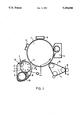
- FIG. 1 diagrammatically illustrates a magnetic printing apparatus in which the method according to the instant invention is used.
- the apparatus comprises a cylindrical image recording medium 1 consisting of a drum of copper or copper-plated aluminum, the surface of which is covered with a galvanically applied cobalt-nickel phosphorus layer about 8 micrometers thick, which has a magnetic coercivity of about 77 kA/m.
- the image-recording medium 1 can rotate in the direction indicated by the arrow.
- a magnetic head array 2 Disposed consecutively along the rotational path of the image recording medium 1, as considered in the direction of rotation there is a magnetic head array 2, with which a latent magnetic image having a resolution of about 400 dpi can be recorded in the magnetizable layer, a developing device 3, an image transfer device 4, a cleaning device 5, and an erase device 6.
- the magnetic head array 2 is of the type described in detail in European Patent Application 87200230.
- the developing device 3 comprises a reservoir 7 for the toner powder 20, a powder supply roller 8 having a rough surface, a toner conveyor 9 which feeds the toner powder 20 into the developing zone 13, and a metering device 10.
- the powder supply roller 8 feeds the toner powder to the toner conveyor 9.
- the latter consists of a magnetic roller having a rotatable electrically conductive non-magnetizable sleeve 11 of, for example, copper and a stationary magnet system 12 inside the sleeve 11.
- the magnet system 12 comprises eight magnet poles magnetized as shown in the drawing.
- the magnet pole situated opposite the image-recording medium 1 generates a magnetic induction of, for example, about 225 gauss at the surface of sleeve 11 immediately thereabove, while the other magnet poles generate an induction of 800 gauss at the surface of the sleeve.
- the lower magnetic induction in the developing zone 13 is of no essential importance to obtaining good image development. All that is important is that there should not be such a magnetic field in the developing zone 13 which creates an erasing effect on the latent magnetic image on the image-recording medium 1.
- the method according to the present invention can also be performed using a toner conveyor so constructed that no magnetic field, or only a very weak magnetic field, is present in the developing zone 13. Embodiments of such toner conveyors are indicated in U.S. Pat. No. 4, 368,687 mentioned above.
- the distance between the sleeve 11 and the image-recording medium 1 can be varied by moving the toner conveyor 9.
- the distance between sleeve 11 and the metering device 10, which consists of aluminum for example and is in the form of a ruler, is adjustable.
- the distance "B" as discussed above, denotes the shortest distance between the sleeve 11 and the metering device 10.
- the electrically conductive sleeves of the toner conveyor 9 and the image-recording medium 1, respectively, are connected to an AC supply 14.
- a powder image developed on the image-recording medium 1 is transferred to an image-receiving material 21 by the transfer device 4.
- the latter is a two-step transfer device known per se, in which the powder image of the image-recording medium 1 is first transferred, by pressure, to a belt 15 bearing a silicone rubber surface covering.
- the belt 15 is heated by heating means (not shown) to soften the powder image transferred thereto.
- the softened powder image is then transferred to and fixed o the receiving material 21 fed to the pressure zone from a supply (not shown).
- the working range of the developing device of the instant illustration is determined by using a toner powder having a resistance of about 3.5 ⁇ 10 5 ohms.meters, a particle size of between 10 and 20 micrometers, and particles containing 20% by volume of a soft magnetic pigment (type Bayferrox B 318 M made by Bayer AG, Germany) and 80% by volume of a polyester resin, the surface being covered with carbon particles. Background-free images of good quality are obtained with the following settings:
- the optimal value for the distance A was found to be between the distance B plus 0.6 to 1.6 mm.
- the difference between distance A and distance B was in the range from 0.6-1 mm, and gradually shifted to higher values with increasing AC voltage.
- the delta w appeared to have a working range of some tenths of a millimeter for each applied Ac voltage. With AC voltages of from about 1200 V to about 600 V this working range was determined to be 0.3 to 0.4 mm.
- the resistance of the toner powder used varied between about 10 3 and 10 9 ohms.meter with the above settings being distance B: 1.3 mm; AC voltage 1500 V, 1800 Hz; speed of rotation of sleeve 11: 45 meters per minute; and speed of rotation of image-recording medium 1: 15 meters per minute.
- Good quality prints are obtained in every case with delta w values between 0.9 and 1.3 mm.
- the quality of the images obtained with the toner powder having a specific resistance of more than 10 8 ohms.meter is a fraction less satisfactory than that of the images obtained with the other toner powders.
- the toner powders used in these tests consisted of particles containing 20% by volume of soft magnetic pigment (Bayferrox B 318 M) and 80% by volume of the polyester resin, the surface being covered with fine carbon particles.
- toner powder in which the particles ranged in size of between 10 and 20 micrometers and consisted of 94% by volume polyester resin, 3% by volume remanent magnetic pigment (type Bayferrox 8140 made by Bayer AG, Germany) and 3% by volume carbon, and which were covered with carbon to a specific resistance of 2 ⁇ 10 5 ohms.meter, a same working range was found as described above for toner powder containing 20% by volume of the soft magnetic pigment.
- the distance between the toner conveyor and the surface of the image-recording medium in the developing zone can be so widely varied that toner powder 20 is deposited on the image-recording medium only when the AC voltage is applied across the developing zone. If further image development is to be avoided for some reason, e.g. in the event of a malfunction in the image transfer device or in the supply of image receiving material, immediate response is possible by switching off the AC supply.
- a multi-color printing apparatus can be configured in a relatively simple manner of the type in which a number of developing devices, e.g.
- each such developing device being filled with toner powder of a specific color and the appropriate color separation images printed in consecutive rotational cycles of the image-recording medium, the separation images being combined in register on a combining medium, e.g. the image-receiving material or an intermediate.
- the development of each of the separation images in the associated color is controlled by applying the AC voltage to the developing device required to be operative.
Landscapes
- Physics & Mathematics (AREA)
- General Physics & Mathematics (AREA)
- Dry Development In Electrophotography (AREA)
- Developing Agents For Electrophotography (AREA)
- Magnetic Brush Developing In Electrophotography (AREA)
Applications Claiming Priority (2)
| Application Number | Priority Date | Filing Date | Title |
|---|---|---|---|
| NL9002462 | 1990-11-12 | ||
| NL9002462A NL9002462A (nl) | 1990-11-12 | 1990-11-12 | Werkwijze en inrichting voor het ontwikkelen van een latent magnetisch beeld. |
Publications (1)
| Publication Number | Publication Date |
|---|---|
| US5154944A true US5154944A (en) | 1992-10-13 |
Family
ID=19857961
Family Applications (1)
| Application Number | Title | Priority Date | Filing Date |
|---|---|---|---|
| US07/789,325 Expired - Fee Related US5154944A (en) | 1990-11-12 | 1991-11-08 | Method and apparatus for developing a latent magnetic image |
Country Status (5)
| Country | Link |
|---|---|
| US (1) | US5154944A (de) |
| EP (1) | EP0486083B1 (de) |
| JP (1) | JP3127014B2 (de) |
| DE (1) | DE69117662T2 (de) |
| NL (1) | NL9002462A (de) |
Cited By (1)
| Publication number | Priority date | Publication date | Assignee | Title |
|---|---|---|---|---|
| US20080242079A1 (en) * | 2007-03-30 | 2008-10-02 | Dingying Xu | In-situ formation of conductive filling material in through-silicon via |
Families Citing this family (1)
| Publication number | Priority date | Publication date | Assignee | Title |
|---|---|---|---|---|
| KR200477992Y1 (ko) | 2015-04-01 | 2015-08-13 | 이성혁 | 관성모멘트를 이용한 골프 스윙용 교정구 |
Citations (4)
| Publication number | Priority date | Publication date | Assignee | Title |
|---|---|---|---|---|
| GB1406983A (en) * | 1972-03-16 | 1975-09-24 | Oce Van Der Grinten Nv | Development of electrostatic charge patterns |
| US4368687A (en) * | 1980-01-28 | 1983-01-18 | Canon Kabushiki Kaisha | Method and apparatus for developing magnetic latent image |
| EP0212669A2 (de) * | 1985-08-30 | 1987-03-04 | Konica Corporation | Entwicklungsverfahren für ein latentes elektrostatisches Bild |
| US4686933A (en) * | 1983-03-17 | 1987-08-18 | Fuji Xerox Co., Ltd | Magnetic recording image developing apparatus |
-
1990
- 1990-11-12 NL NL9002462A patent/NL9002462A/nl not_active Application Discontinuation
-
1991
- 1991-10-31 JP JP03286528A patent/JP3127014B2/ja not_active Expired - Fee Related
- 1991-11-01 EP EP91202840A patent/EP0486083B1/de not_active Expired - Lifetime
- 1991-11-01 DE DE69117662T patent/DE69117662T2/de not_active Expired - Fee Related
- 1991-11-08 US US07/789,325 patent/US5154944A/en not_active Expired - Fee Related
Patent Citations (4)
| Publication number | Priority date | Publication date | Assignee | Title |
|---|---|---|---|---|
| GB1406983A (en) * | 1972-03-16 | 1975-09-24 | Oce Van Der Grinten Nv | Development of electrostatic charge patterns |
| US4368687A (en) * | 1980-01-28 | 1983-01-18 | Canon Kabushiki Kaisha | Method and apparatus for developing magnetic latent image |
| US4686933A (en) * | 1983-03-17 | 1987-08-18 | Fuji Xerox Co., Ltd | Magnetic recording image developing apparatus |
| EP0212669A2 (de) * | 1985-08-30 | 1987-03-04 | Konica Corporation | Entwicklungsverfahren für ein latentes elektrostatisches Bild |
Cited By (2)
| Publication number | Priority date | Publication date | Assignee | Title |
|---|---|---|---|---|
| US20080242079A1 (en) * | 2007-03-30 | 2008-10-02 | Dingying Xu | In-situ formation of conductive filling material in through-silicon via |
| US7851342B2 (en) * | 2007-03-30 | 2010-12-14 | Intel Corporation | In-situ formation of conductive filling material in through-silicon via |
Also Published As
| Publication number | Publication date |
|---|---|
| JPH04285989A (ja) | 1992-10-12 |
| NL9002462A (nl) | 1992-06-01 |
| EP0486083A1 (de) | 1992-05-20 |
| DE69117662T2 (de) | 1996-09-19 |
| EP0486083B1 (de) | 1996-03-06 |
| DE69117662D1 (de) | 1996-04-11 |
| JP3127014B2 (ja) | 2001-01-22 |
Similar Documents
| Publication | Publication Date | Title |
|---|---|---|
| US3804511A (en) | Method and apparatus utilizing magnetic storage for transferring graphical information | |
| US4402000A (en) | Electrographic recording method and apparatus with control of toner quantity at recording region | |
| GB1567219A (en) | Electrostatic developing method | |
| US5154944A (en) | Method and apparatus for developing a latent magnetic image | |
| US4233382A (en) | Electrostatic transfer of magnetically held toner images | |
| JP3237818B2 (ja) | 印刷ヘツド構造体及びdep装置 | |
| CA1142996A (en) | Electrographic recording method and apparatus | |
| GB2109310A (en) | Electrographic printing | |
| US4254206A (en) | Process for magnetically transferring a powder image | |
| EP0573096B1 (de) | Bilderzeugungsvorrichtung | |
| EP0740224A1 (de) | Direkte elektrostatische Druckvorrichtung (DEP) | |
| US6012802A (en) | Device for direct electrostatic print (DEP) comprising individual control print and control back electrodes | |
| US5900893A (en) | Direct electrostatic printing device wherein the speeds of a magnetic brush and a receiving substrate are related to each other | |
| US4433041A (en) | Recording method | |
| US4232323A (en) | Magnetographic apparatus | |
| US4636449A (en) | Electrostatic printing process | |
| US5272033A (en) | Method of forming visible images | |
| CA1107342A (en) | Electrostatic transfer of magnetically held toner images | |
| US6109729A (en) | Direct electrostatic printing device having a printhead structure with control electrodes on one side of a slit aperture | |
| US6070966A (en) | Method for direct electrostatic printing in which toner particles are extracted directly from a magnetic brush carrying a two-component developer with conductive carrier | |
| US4965598A (en) | Printing apparatus | |
| JPS6361266A (ja) | 閃光定着型磁気潜像現像用磁性トナ− | |
| JPS58136054A (ja) | 多色記録方法 | |
| JPS6125159A (ja) | 画像形成装置 | |
| JPH1081030A (ja) | 直接静電印刷装置 |
Legal Events
| Date | Code | Title | Description |
|---|---|---|---|
| AS | Assignment |
Owner name: OCE-NEDERLAND B.V. Free format text: ASSIGNMENT OF ASSIGNORS INTEREST.;ASSIGNOR:KLERKEN, PIERRE A. M.;REEL/FRAME:005948/0239 Effective date: 19911120 |
|
| FEPP | Fee payment procedure |
Free format text: PAYOR NUMBER ASSIGNED (ORIGINAL EVENT CODE: ASPN); ENTITY STATUS OF PATENT OWNER: LARGE ENTITY |
|
| FPAY | Fee payment |
Year of fee payment: 4 |
|
| FPAY | Fee payment |
Year of fee payment: 8 |
|
| REMI | Maintenance fee reminder mailed | ||
| LAPS | Lapse for failure to pay maintenance fees | ||
| STCH | Information on status: patent discontinuation |
Free format text: PATENT EXPIRED DUE TO NONPAYMENT OF MAINTENANCE FEES UNDER 37 CFR 1.362 |
|
| FP | Lapsed due to failure to pay maintenance fee |
Effective date: 20041013 |