US5159219A - Opposed-magnet bearing with interposed superconductor - Google Patents
Opposed-magnet bearing with interposed superconductor Download PDFInfo
- Publication number
- US5159219A US5159219A US07/701,206 US70120691A US5159219A US 5159219 A US5159219 A US 5159219A US 70120691 A US70120691 A US 70120691A US 5159219 A US5159219 A US 5159219A
- Authority
- US
- United States
- Prior art keywords
- magnet
- superconductor
- magnets
- magnetic field
- thrust
- Prior art date
- Legal status (The legal status is an assumption and is not a legal conclusion. Google has not performed a legal analysis and makes no representation as to the accuracy of the status listed.)
- Expired - Lifetime
Links
- 239000002887 superconductor Substances 0.000 title claims abstract description 117
- 230000005291 magnetic effect Effects 0.000 claims abstract description 99
- 238000000034 method Methods 0.000 claims abstract description 12
- 239000000463 material Substances 0.000 description 40
- 230000000087 stabilizing effect Effects 0.000 description 14
- 230000000694 effects Effects 0.000 description 7
- 238000005339 levitation Methods 0.000 description 7
- 230000005415 magnetization Effects 0.000 description 7
- IJGRMHOSHXDMSA-UHFFFAOYSA-N Atomic nitrogen Chemical compound N#N IJGRMHOSHXDMSA-UHFFFAOYSA-N 0.000 description 6
- 238000013461 design Methods 0.000 description 5
- 230000004907 flux Effects 0.000 description 5
- 230000003993 interaction Effects 0.000 description 5
- 230000004044 response Effects 0.000 description 5
- 150000001875 compounds Chemical class 0.000 description 4
- 230000007423 decrease Effects 0.000 description 4
- 238000006073 displacement reaction Methods 0.000 description 4
- 230000008901 benefit Effects 0.000 description 3
- 230000008859 change Effects 0.000 description 3
- 238000009826 distribution Methods 0.000 description 3
- 239000007789 gas Substances 0.000 description 3
- 229910052757 nitrogen Inorganic materials 0.000 description 3
- 239000003507 refrigerant Substances 0.000 description 3
- 238000013519 translation Methods 0.000 description 3
- 230000006978 adaptation Effects 0.000 description 2
- 239000001307 helium Substances 0.000 description 2
- 229910052734 helium Inorganic materials 0.000 description 2
- SWQJXJOGLNCZEY-UHFFFAOYSA-N helium atom Chemical compound [He] SWQJXJOGLNCZEY-UHFFFAOYSA-N 0.000 description 2
- 239000012212 insulator Substances 0.000 description 2
- 239000007788 liquid Substances 0.000 description 2
- 239000000314 lubricant Substances 0.000 description 2
- 238000004519 manufacturing process Methods 0.000 description 2
- 230000021715 photosynthesis, light harvesting Effects 0.000 description 2
- 230000008569 process Effects 0.000 description 2
- 230000001846 repelling effect Effects 0.000 description 2
- 230000002441 reversible effect Effects 0.000 description 2
- 239000000523 sample Substances 0.000 description 2
- 239000000725 suspension Substances 0.000 description 2
- 230000007704 transition Effects 0.000 description 2
- OKTJSMMVPCPJKN-UHFFFAOYSA-N Carbon Chemical compound [C] OKTJSMMVPCPJKN-UHFFFAOYSA-N 0.000 description 1
- BTGZYWWSOPEHMM-UHFFFAOYSA-N [O].[Cu].[Y].[Ba] Chemical class [O].[Cu].[Y].[Ba] BTGZYWWSOPEHMM-UHFFFAOYSA-N 0.000 description 1
- 230000009471 action Effects 0.000 description 1
- 230000000712 assembly Effects 0.000 description 1
- 238000000429 assembly Methods 0.000 description 1
- 230000004888 barrier function Effects 0.000 description 1
- 229910052797 bismuth Inorganic materials 0.000 description 1
- JCXGWMGPZLAOME-UHFFFAOYSA-N bismuth atom Chemical compound [Bi] JCXGWMGPZLAOME-UHFFFAOYSA-N 0.000 description 1
- 238000009835 boiling Methods 0.000 description 1
- 239000000919 ceramic Substances 0.000 description 1
- 239000011248 coating agent Substances 0.000 description 1
- 238000000576 coating method Methods 0.000 description 1
- 239000012141 concentrate Substances 0.000 description 1
- 239000000356 contaminant Substances 0.000 description 1
- 239000002826 coolant Substances 0.000 description 1
- 239000010949 copper Substances 0.000 description 1
- 238000005520 cutting process Methods 0.000 description 1
- 238000011161 development Methods 0.000 description 1
- 239000000428 dust Substances 0.000 description 1
- 238000005516 engineering process Methods 0.000 description 1
- 230000005294 ferromagnetic effect Effects 0.000 description 1
- 239000003302 ferromagnetic material Substances 0.000 description 1
- 239000011888 foil Substances 0.000 description 1
- 229910002804 graphite Inorganic materials 0.000 description 1
- 239000010439 graphite Substances 0.000 description 1
- 238000010438 heat treatment Methods 0.000 description 1
- 238000010348 incorporation Methods 0.000 description 1
- 238000009413 insulation Methods 0.000 description 1
- 238000003475 lamination Methods 0.000 description 1
- 239000010687 lubricating oil Substances 0.000 description 1
- 230000007246 mechanism Effects 0.000 description 1
- 229910052751 metal Inorganic materials 0.000 description 1
- 239000002184 metal Substances 0.000 description 1
- 239000002907 paramagnetic material Substances 0.000 description 1
- 239000002245 particle Substances 0.000 description 1
- 230000035515 penetration Effects 0.000 description 1
- 239000011148 porous material Substances 0.000 description 1
- 238000004064 recycling Methods 0.000 description 1
- 238000009877 rendering Methods 0.000 description 1
- 238000011160 research Methods 0.000 description 1
- 239000007787 solid Substances 0.000 description 1
- 230000002459 sustained effect Effects 0.000 description 1
- 229910052716 thallium Inorganic materials 0.000 description 1
- BKVIYDNLLOSFOA-UHFFFAOYSA-N thallium Chemical compound [Tl] BKVIYDNLLOSFOA-UHFFFAOYSA-N 0.000 description 1
Images


Classifications
-
- F—MECHANICAL ENGINEERING; LIGHTING; HEATING; WEAPONS; BLASTING
- F16—ENGINEERING ELEMENTS AND UNITS; GENERAL MEASURES FOR PRODUCING AND MAINTAINING EFFECTIVE FUNCTIONING OF MACHINES OR INSTALLATIONS; THERMAL INSULATION IN GENERAL
- F16C—SHAFTS; FLEXIBLE SHAFTS; ELEMENTS OR CRANKSHAFT MECHANISMS; ROTARY BODIES OTHER THAN GEARING ELEMENTS; BEARINGS
- F16C32/00—Bearings not otherwise provided for
- F16C32/04—Bearings not otherwise provided for using magnetic or electric supporting means
- F16C32/0406—Magnetic bearings
- F16C32/044—Active magnetic bearings
-
- F—MECHANICAL ENGINEERING; LIGHTING; HEATING; WEAPONS; BLASTING
- F16—ENGINEERING ELEMENTS AND UNITS; GENERAL MEASURES FOR PRODUCING AND MAINTAINING EFFECTIVE FUNCTIONING OF MACHINES OR INSTALLATIONS; THERMAL INSULATION IN GENERAL
- F16C—SHAFTS; FLEXIBLE SHAFTS; ELEMENTS OR CRANKSHAFT MECHANISMS; ROTARY BODIES OTHER THAN GEARING ELEMENTS; BEARINGS
- F16C32/00—Bearings not otherwise provided for
- F16C32/04—Bearings not otherwise provided for using magnetic or electric supporting means
- F16C32/0406—Magnetic bearings
- F16C32/0408—Passive magnetic bearings
- F16C32/0436—Passive magnetic bearings with a conductor on one part movable with respect to a magnetic field, e.g. a body of copper on one part and a permanent magnet on the other part
- F16C32/0438—Passive magnetic bearings with a conductor on one part movable with respect to a magnetic field, e.g. a body of copper on one part and a permanent magnet on the other part with a superconducting body, e.g. a body made of high temperature superconducting material such as YBaCuO
-
- H—ELECTRICITY
- H02—GENERATION; CONVERSION OR DISTRIBUTION OF ELECTRIC POWER
- H02K—DYNAMO-ELECTRIC MACHINES
- H02K55/00—Dynamo-electric machines having windings operating at cryogenic temperatures
-
- H—ELECTRICITY
- H02—GENERATION; CONVERSION OR DISTRIBUTION OF ELECTRIC POWER
- H02K—DYNAMO-ELECTRIC MACHINES
- H02K7/00—Arrangements for handling mechanical energy structurally associated with dynamo-electric machines, e.g. structural association with mechanical driving motors or auxiliary dynamo-electric machines
- H02K7/08—Structural association with bearings
- H02K7/09—Structural association with bearings with magnetic bearings
-
- Y—GENERAL TAGGING OF NEW TECHNOLOGICAL DEVELOPMENTS; GENERAL TAGGING OF CROSS-SECTIONAL TECHNOLOGIES SPANNING OVER SEVERAL SECTIONS OF THE IPC; TECHNICAL SUBJECTS COVERED BY FORMER USPC CROSS-REFERENCE ART COLLECTIONS [XRACs] AND DIGESTS
- Y02—TECHNOLOGIES OR APPLICATIONS FOR MITIGATION OR ADAPTATION AGAINST CLIMATE CHANGE
- Y02E—REDUCTION OF GREENHOUSE GAS [GHG] EMISSIONS, RELATED TO ENERGY GENERATION, TRANSMISSION OR DISTRIBUTION
- Y02E40/00—Technologies for an efficient electrical power generation, transmission or distribution
- Y02E40/60—Superconducting electric elements or equipment; Power systems integrating superconducting elements or equipment
-
- Y—GENERAL TAGGING OF NEW TECHNOLOGICAL DEVELOPMENTS; GENERAL TAGGING OF CROSS-SECTIONAL TECHNOLOGIES SPANNING OVER SEVERAL SECTIONS OF THE IPC; TECHNICAL SUBJECTS COVERED BY FORMER USPC CROSS-REFERENCE ART COLLECTIONS [XRACs] AND DIGESTS
- Y10—TECHNICAL SUBJECTS COVERED BY FORMER USPC
- Y10S—TECHNICAL SUBJECTS COVERED BY FORMER USPC CROSS-REFERENCE ART COLLECTIONS [XRACs] AND DIGESTS
- Y10S505/00—Superconductor technology: apparatus, material, process
- Y10S505/825—Apparatus per se, device per se, or process of making or operating same
- Y10S505/876—Electrical generator or motor structure
Definitions
- the present invention relates to novel magnet-superconductor systems, and to bearings and other articles utilizing magnet-superconductor systems.
- the present invention relates to magnet-superconductor systems having high thrust and high stability and to a method for increasing the thrust and stability of magnet-superconductor systems.
- the present invention relates to bearings and other articles utilizing magnet-superconductor systems having high thrust and high stability, and to methods of increasing the thrust and stability of bearings and other articles utilizing magnet-superconductor systems.
- air bearings require a completely pneumatic system, including pumps, valves, seals, and conduits, for their operation.
- Another shortcoming of air bearings is that they result in a continuous energy loss.
- a high speed cryo-cooler system in outer space applications would suffer a 10-20 watt energy loss due to bearing friction losses.
- use of an air system adds significant cost, size, and weight to the bearing package and introduces various reliability problems normally associated with pneumatic system components.
- magnetically suspended bearings As an alternative to air bearings, magnetically suspended bearings have been developed. Conventional magnetically suspended bearings ar generally unstable and require for their operability control means, such as rapidly acting feedback control systems, to compensate for displacements from the set point. Until recently, magnetic bearings have been of one of two types--either permanent magnets or electromagnets.
- Electromagnets which can supply considerably more magnetic force than comparable permanent magnets, are much more convenient to use and are thus preferred for use in conjunction with feedback control systems. However, because of the required feedback control systems, use of electromagnets adds considerably to the cost, size, and operational complexity of the system.
- HTS high temperature superconducting
- the new CuO high temperature superconductors may be cooled with liquid nitrogen, which is a far less costly refrigerant than helium.
- liquid nitrogen is a far less costly refrigerant than helium.
- the HTS compounds simplify and enhance the reliability of commercial applications of superconductors. Liquid nitrogen is about 2000 times more efficient to use in terms of cost, when both the refrigerant itself and the associated refrigerant unit design are considered.
- Type I and Type II Superconductive materials are of two basic types, designated as Type I and Type II. Efforts have been made in the past to improve magnetic bearing technology by maintaining either the bearing member or the rotating member, or both, in a Type I superconducting state to achieve sufficient magnetic pressure to provide the desired degree of levitation. Unlike Type II superconductors, Type I superconductors are incapable of effecting suspension.
- Type I superconductors feature perfect diamagnetism up to a critical applied field, at which point superconductivity is lost and the magnetization of the sample rises abruptly.
- Examples of superconducting bearings of Type I materials can be found in U.S. Pat. Nos. 3,493,274 and 3,026,151. In order to achieve stability in these systems, the bearing structures must rely on either a mechanical rotary support: or must employ superconductors shaped to provide a laterally stable configuration.
- Type II superconductors involve Type II materials. Whereas a Type I superconductor completely blocks out magnetic flux from its interior, a phenomenon known as diamagnetism, Type II superconductors allow a certain amount of magnetic flux to penetrate into the interior of the material, producing a suspension effect in addition to a levitation effect. Under such conditions, circulating superconducting currents are established within the superconductor.
- U.S. Pat. No. 4,886,778 discloses a rotating shaft having two ends, each of which contains a permanent magnet and rotates in a socket clad with superconducting material. The shaft is made to levitate above the sockets by the repulsive forces which exist between the magnets and the superconductors.
- the incorporation of superconductors into the bearing design offers the possibility of rendering the bearings entirely passive.
- the design disclosed in U.S. Pat. No. 4,886,778 has the potential for achieving very high rotational speeds, in excess of ten thousand rpm.
- the interaction between the rotating magnetic axial element and its stationary superconducting support takes place across a gap permeated by a strong magnetic field emanating from permanent magnets embedded in the rotating element.
- U.S. Pat. No. 4,879,537 discloses the use of a superconductor located in the magnet-magnet attraction axis between two attracting magnets. For attracting magnets the instability is along the magnet-magnet attraction axis. However, this system suffers because it is not always desirable to stabilize two attracting magnets by placing a superconductor in the magnet-magnet attraction axis between magnets.
- auxiliary control system activated by signals from sensors, such as proximity probes, which are used detect the position of the shaft.
- the control system would be based on conventional feedback systems such as a gas, foil, tilt pad, or electromagnetic systems and would be activated whenever higher forces are required than those which the magnet is able to produce.
- the auxiliary system would remain activated until such required forces are again within the operating range of the superconductor and magnet bearing system.
- magnet-superconductor systems having high stability and generating or supporting high thrust which successfully address the shortcomings of the prior art configurations.
- Such systems comprise a first magnet, a second magnet, and a superconductor.
- the magnets are in relative motion to each other, may be permanent, electromagnets, superconducting electromagnets or superconducting replicas and they may be oriented to attract or repulse each other.
- the superconductor comprises type II superconductor material and is affixed such that it is in relative motion with respect to one of the magnets, but stationary with respect to the other magnet.
- the superconductor In repulsive systems, the superconductor is placed between the magnets, and in attractive systems, the superconductor is placed alongside one of the magnets outside of the attraction axis. High thrust and stability is achieved by increasing the magnetic field of the magnet moving relative to the superconductor.
- the bearing assemblies of the present invention comprise a rotating member and at least one stationary member. Mounted on the rotating member is a first magnet, with a second magnet mounted on the stationary member.
- the superconductor is located such that the superconductor is stationary with respect to one magnet, but in motion relative to the other magnet. This is easily accomplished by mounting the superconductor and the first magnet, on the rotating member so that they are stationary with respect to each other, and mounting the second magnet alongside the rotating shaft s that the second magnet and the superconductor are in relative motion.
- the thrust and stability of the bearing system is increased by increasing the magnetic field of the second magnet, either by replacing it with a stronger magnet or by applying more current to the second magnet if it is an electromagnet.
- the present invention also discloses a multi-staged magnetic bearing which combines stages of magnets to allow higher axial forces to be carried by the bearing shaft.
- Each stage comprises a stabilizing material located on the bearing shaft, and magnets placed annularly around, and axially on either side of the stabilizing material.
- Multi-staging is crucial in designs required to handle high thrust with stability when the requirement exceeds that which can be provided in a single-stage design by the strongest magnets limited either by technical feasibility or other limitations.
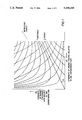
- FIG. 1 is a graph showing contours of equal thrust and equal stability in the B 1 -B 2 plane, for a system comprising a first magnet, a second magnet, and a superconductor, in which the first magnet has a magnetic field B 1 and the second magnet has a magnetic field B 2 , the superconductor is a type II superconductor is in motion relative to magnet 1 but stationary with respect to magnet 2.
- the solid contours represent constant stability (or instability) lines, and the dotted contours represent constant thrust lines.
- FIG. 2 is a cross-sectional view of a rotating shaft having a superconductor magnet hydrid thrust and journal bearing.
- FIG. 3 is a cross-sectional view of a thrust supporting element.
- FIG. 4 is a cross-sectional view of a stabilizing element.
- FIG. 5 is a cross-sectional view of an integrated thrust supporting and stabilizing element.
- FIG. 6 is a cross-sectional view of a multi-stage bearing utilizing thrust supporting and stabilizing elements as shown in FIG. 3 and FIG. 4.
- FIG. 7 is a cross-sectional view of a rotating shaft having a superconductor magnet hydrid thrust and journal bearing.
- the present invention is of a novel magnet-superconductor system. Specifically, this invention takes advantage of the interaction between a type II high temperature superconductor that moves relative to the magnetic field of one magnet and is stationary with respect to another magnet.
- the magnet-superconductor systems of the present invention comprise a first magnet having a magnetic field B 1 and a second magnet moving relative to the first having a magnetic field B 2 , and a type II superconductor moving relative the first magnet but not with respect to the second magnet.
- the superconductor is interposed between the repulsing magnets.
- the superconductor is placed alongside one of the magnets.
- HTS high temperature superconducting
- Superconducting materials suitable for use in the present invention are the high temperature superconductors, of Type II.
- high temperature superconductors are generally perovskite materials, for example of the barium-yttrium copper oxide class.
- a preferred material is YBa 2 Cu 3 O x .
- Thallium, bismuth or other ceramic-based compounds which exhibit Type II superconducting properties are also acceptable.
- Type II superconductors are characterized by first and second values of critical field, H c ,1 and H c ,2, where field penetration first occurs above H c ,1.
- the stability and the thrust pressure are no longer directly related to each other, but can be independently varied.
- FIG. 1 is a graph showing contours of equal thrust and equal stability in the B 1 -B 2 plane, for a system which comprises a first magnet M 1 having a magnetic field B 1 and a second magnet M 2 moving relative to the first having a magnetic field B 2 , and a type II superconductor moving relative to magnet 1 but stationary with respect to magnet 2.
- FIG. 1 shows that increasing the magnetic field strength of the magnet stationary with respect to the superconductor will increase the thrust but will decrease the stability.
- increasing the magnetic field strength of the magnet moving relative to the superconductor will increase both the thrust and the stability.
- the magnetic field existing in the superconductor before it is cooled to below the superconducting transition temperature remains generally the same after the superconductor is cooled sufficiently to turn superconducting.
- the induced currents would change from being non-existent to a small value. Under such conditions, the superconductor cannot support any voltage, and hence the magnetic flux threading through its interior must stay constant.
- the response of the field cooled (the magnets and the superconductors are assembled into the bearing first, and then cooled to below the superconducting transition temperature) superconductor to an initial small disturbance in an external magnetic field is to completely shield its interior from any changes of the existing magnetic field.
- This response is generally reversible and not dissipative.
- ⁇ is a vector that depends only on the geometry of the two magnets.
- ⁇ -grad ⁇
- ⁇ is a tensor that embodies the dependence on the geometry of magnet M1 and the superconductor.
- the first term represents the change of the force on magnet M1, due to a small displacement of magnet M2.
- ⁇ has non-negative trace.
- the second term arises from the force between magnet M1 and the induced currents on the superconductor, when the superconductor is also given the same displacement. This force is proportional to the magnetization of magnet M1 and the induced current on the superconductor, which is, in turn, proportional to the magnetization of magnet M1 also. Since there is no relative displacement of magnet M2 and the superconductor, there is no induced current on the superconductor that is attributable to magnet M2.
- FIG. 1 are mapped out the contours of equal thrust and equal stability in the B 1 -B 2 plane. From these, it can been seen that changing the magnetization of magnet M2, which is constrained to move with the superconductor as a whole, results in trading the stability for, or against the thrust that can be sustained; whereas, changing the magnetization of magnet M1, either enhances or decreases both the stability and the force.
- FIG. 1 The above principles of FIG. 1 can be applied to magnetic bearings.
- the strongest magnets which are either superconducting or electromagnets, are not very convenient for rotating at high speeds.
- magnet M1 The rotating shaft of the bearing could then be a rigid combination of a superconductor and a permanent magnet, which need not be as strongly magnetized.
- the sustainable force and the stability are decoupled from each other.
- the sustainable force comes largely from the interaction between the magnets, while the interaction between the magnets and the superconductor provides the overall stability, but the distribution of this stability into the axial and radial components is strongly affected by the interaction between the magnets.
- FIG. 2 illustrates one embodiment of the present invention.
- FIG. 2 shows a superconductor-magnet hydrid bearing with electromagnet stators having a journal bearing 100 and thrust bearing 200.
- the journal bearing 100 includes a rotating member 106, typically an elongated cylindrical shaft, which is to be centered at a particular desired location.
- Shaft 106 is typically rotating and is connected to some device, such as a motor, a generator, and the like. It is desirable to keep the rotating shaft 106 at a particular location and, in particular, to avoid any translation of any portion of shaft 106 in a direction extending radially outward from shaft 106 or along its axis.
- journal bearing shaft magnet 105 Affixed to and moving with rotating shaft 106 is journal bearing shaft magnet 105.
- Journal bearing shaft magnet 105 is generally a permanent magnet because it is generally not very convenient to have superconducting or electromagnets rotating at high speeds.
- journal magnet 110 Located annularly around rotating shaft 106 at the location of journal bearing shaft magnet 105 is journal magnet 110.
- journal magnet 110 may be any type of magnet including permanent, electromagnet, superconducting electromagnet and superconducting replicas, it is shown in FIG. 2 as an electromagnet, with journal electromagnet coils 112.
- Superconducting electromagnets utilize superconducting material as the electrical coil. Superconducting replicas are made by trapping a magnetic field in a superconductor. The field remains trapped as long as the material remains superconducting.
- Journal magnet 110 may comprise one annularly shaped magnet, or a number of magnets placed annularly around rotating shaft 106 at the location of journal bearing shaft magnet 105. Located between magnet 105 and magnet 110 is journal superconducting material 120. Superconducting material 120 is positioned to move relative to the magnetic field of journal magnet 110 but not with respect to the magnetic field of journal shaft magnet 105. This is easily accomplished by affixing superconducting material 120 to the shaft along with journal shaft magnet 105 as shown. Since superconducting material 120 is moving with respect to the magnetic field of journal magnet 110, increasing the magnetic field of journal magnet 110 by increasing the current through coils 112 will increase both the thrust and the stability of the journal bearing.
- journal bearing 100 placed axially along shaft 106.
- thrust bearing 200 Located at the bottom end of shaft 106 is thrust bearing 200 comprising thrust bearing magnet 217, thrust bearing shaft magnet 208 and thrust superconductor 222. Affixed to and moving with rotating shaft 106 is thrust bearing shaft magnet 208. Thrust bearing shaft magnet 208 is generally a permanent magnet because it is generally not very convenient to have superconducting or electromagnets rotating at high speeds. Located below thrust bearing shaft magnet 208 is thrust bearing magnet 217. Although thrust bearing magnet may be any type of magnet including permanent, electromagnet, superconducting electromagnet and superconducting replicas, it is shown in FIG. 2 as an electromagnet, with thrust electromagnet coils 218.
- Superconducting material 222 is positioned to move relative to the magnetic field of thrust bearing magnet 217 but not with respect to the magnetic field of thrust bearing shaft magnet 208. This is easily accomplished by affixing superconducting material 222 to the shaft along with thrust bearing shaft magnet 208 as shown. Since superconducting material 222 is moving with respect to the magnetic field of thrust bearing magnet 217 increasing the magnetic field of thrust bearing magnet 217 by increasing the current through coils 218 will increase both the thrust and the stability of the thrust bearing.
- rotating shaft is supported and suspended by thrust bearing 200.
- One or more journal bearings 100 prevent any translation of shaft 106 radially from its desired position.
- the magnets of thrust bearing 100 and the one or more journal bearings 200 are such that the magnetic systems are in the stable region of FIG. 1.
- the repulsive force of the thrust bearing maintains the rotating shaft suspended above the thrust bearing.
- the repulsive forces of the one or more journal bearings serve to automatically center and stabilize the rotating member in the radial direction.
- FIG. 3 shows a thrust supporting element 300 of the present invention.
- the thrust supporting element 300 resists an axial force F A on rotating member 106, such as for example gas flow in a turbine.
- Thrust supporting element 300 is composed of a thrust magnet 320 that is affixed to and rotates with shaft 106.
- Thrust magnet 320 is generally a permanent magnet because it is generally not very convenient to have superconducting or electromagnets rotating at high speeds.
- Repulsion magnet 310 is positioned annularly around and axially down from force F A to both repulse shaft 106 back toward force F A , and to automatically center and stabilize the rotating member 106 in the radial direction.
- Repulsion magnet 310 may be any type of magnet including permanent, electromagnet, superconducting electromagnet and superconducting replicas.
- Repulsion magnet 310 may be an annularly shaped magnet or a number of magnets placed annularly around shaft 106.
- Attractive magnet 315 Situated annularly around and axially toward force F A to urge shaft 106 in the direction from which force F A is acting is attractive magnet 315. Attractive magnet 315 also serves to automatically center and stabilize the rotating member 106 in the radial direction. Attractive magnet 315 may be any type of magnet including permanent, electromagnet, superconducting electromagnet and superconducting replicas. Attractive magnet 315 may be an annularly shaped magnet or a number of magnets placed annularly around shaft 106.
- the repulsive magnet 310 and the attractive magnet 315 act to both resist the axial load, and automatically center and stabilize the rotating member 106 in the radial direction.
- FIG. 4 shows a stabilizing element 400 of the present invention.
- Stabilizing element 400 is composed of a stabilizing superconductor 420 that is affixed to and rotates with shaft 106.
- Magnet 410 is positioned annularly around and axially down from force F A to maintain shaft 106 at its central position, and automatically center and stabilize the rotating member 106 in the radial direction.
- Magnet 410 may be any type of magnet including permanent, electromagnet, superconducting electromagnet and superconducting replicas.
- Magnet 410 may be an annularly shaped magnet or a number of magnets placed annularly around shaft 106.
- Magnet 415 Situated annularly around and axially toward force F A to prevent shaft 106 from moving toward or away from force F A , and automatically center and stabilize the rotating member 106 in the radial direction is magnet 415.
- Magnet 415 may be any type of magnet including permanent or electromagnets.
- Magnet 415 may be an annularly shaped magnet or a number of magnets placed annularly around shaft 106.
- FIG. 5 shows an integrated thrust supporting and stabilizing element incorporating the systems as shown in FIG. 3 and FIG. 4 into one system.
- Magnets 510 and 515 are positioned axially on each side of integrated thrust supporting and stabilizing element 520.
- Magnets 510 and 515 may be any type of magnet including including permanent, electromagnet, superconducting electromagnet and superconducting replicas.
- Magnets 510 and 515 may be an annularly shaped magnet or a number of magnets placed annularly around shaft 106.
- Integrated thrust supporting and stabilizing element 520 comprises magnet 520b and superconductor 520a.
- Magnet 520b is generally a permanent magnet because it is generally not very convenient to have superconducting or electromagnets rotating at high speeds.
- Each stage in multi-stage bearing system can be comprised of either (a) thrust supporting element, with magnets placed annularly around and axially on the bearing shaft, exemplified in FIG. 3; or (b) a stabilizing element with magnets placed annularly around the bearing shaft and type II HTS material axially on the bearing shaft, exemplified in FIG. 4, or type II HTS material annularlyly around the bearing shaft and magnets axially o the bearing shaft; or (c) an integrated thrust and stabilizing element, combining the ideas embodied in (a) and (b) described above, and exemplified in FIG. 5.
- the multi-stage bearing can combine these stages in any proportion to acquire a desirable level of thrust to be supported with sufficient stability.
- the ultimate strength of the multi-stage bearing is the accumulative strength of the individual stages.
- FIG. 6 shows an example of a multi-stage bearing system comprising two each of the thrust supporting element 300 of FIG. 3 and the stabilizing element 400 of FIG. 4.
- a multiplicity of the integrated elements of FIG. 6 could also be incorporated in a multi-stage bearing system.
- Utilizing the accumulative strength of each stage in such a multi-stage bearing system helps to overcome any barriers to attaining high thrust with stability that are due to the limitations in the strength of the magnets and the amount of current that can be passed through electromagnets.
- FIG. 7 shows a cross-sectional view of a rotating shaft 106 having journal bearing 600 and thrust bearing 700, with each bearing utilizing attracting magnet systems.
- journal bearing shaft magnet 605 Affixed to and moving with rotating shaft 106 is journal bearing shaft magnet 605.
- Journal bearing shaft magnet 605 is generally a permanent magnet because it is generally not very convenient to have superconducting or electromagnets rotating at high speeds.
- journal magnet 610 Located around rotating shaft 106 at the location of journal bearing shaft magnet 605 is journal magnet 610.
- journal magnet may be any type of magnet including permanent, electromagnet, superconducting electromagnet and superconducting replicas, it is shown in FIG. 7 as a permanent magnet.
- Journal magnet 610 may comprise one annularly shaped magnet, or a number of magnets placed annularly around rotating shaft 106 at the location of journal bearing shaft magnet 605. Located above and below magnet 605 and magnet 610 is journal superconducting material 620. Superconducting material 620 is positioned to move relative to the journal magnet 610 but not with respect to journal shaft magnet 605. This is easily accomplished by affixing superconducting material 620 to the shaft along with journal shaft magnet 605 as shown. Since superconducting material 620 is moving with respect to the magnetic field of journal magnet 610 increasing the magnetic field of journal magnet 610 will increase both the thrust and the stability of the journal bearing.
- journal bearing 600 placed axially along shaft 606.
- thrust bearing 700 Located at the bottom end of shaft 106 is thrust bearing 700 comprising thrust bearing magnet 717, thrust bearing shaft magnet 708 and thrust superconductor 722. Affixed to and moving with rotating shaft 106 is thrust bearing shaft magnet 708. Thrust bearing shaft magnet 708 is generally a permanent magnet because it is generally not very convenient to have superconducting or electromagnets rotating at high speeds. Located below thrust bearing shaft magnet 708 is thrust bearing magnet 717. Although thrust bearing magnet may be any type of magnet including permanent, electromagnet, superconducting electromagnet and superconducting replicas, it is shown in FIG. 2 a permanent magnet. Superconducting material 722 is positioned to move relative to the magnetic field of thrust bearing magnet 717 but not with respect to the magnetic field of thrust bearing shaft magnet 708.
- rotating shaft resists axial load F A by the attractive force between magnets 708 and 717.
- One or more journal bearings 700 prevent any translation of shaft 106 radially from its desired position.
- the magnets of thrust bearing 700 and the one or more journal bearings 700 are such that the magnetic systems are in the stable region of FIG. 1.
- the attractive force of the thrust bearing resists axial load F A .
- the attractive forces of the one or more journal bearings serve to automatically center and stabilize the rotating member in the radial direction.
- electromagnets are utilized in any embodiment of the present invention that the electrical coils of the electromagnets to be produced from a high temperature superconducting material. Coils made from such materials and kept at temperatures below the critical temperature have the ability to sustain a current undiminished. Such an embodiment, involving HTS electromagnets, would thus be quite useful, for example, in outer space applications where low temperatures are easy to maintain and where it is important to use bearings which are as small as possible in order to minimize the payload of the launching rocket.
- the magnetic fields of permanent magnets utilized may be made more uniform.
- certain asymmetries are introduced which cause the produced magnet or core to generate a non-uniform magnetic field. Such asymmetry results in the dissipation of energy and is to be avoided or minimized.
- the present invention may also be utilized, not only to increase the stabiliy and thrust of a magnetic system, but may also be used as a control mechanism to vary the stability and thrust of the system between different states as desired.
- the magnetic field of the magnet in motion relative to the superconducter could be varied, wherein said magnet is an electromagnet, in response to a need for greater or lesser thrust to meet a given situation as may be determined by an automatic sensing device.
- twinning is meant the process of cutting a magnet, or simple dipole, in a direction perpendicular to its internal magnetic field lines into two or more sections. The sections of the dipole are then rotated relative to each until a relative position is found which tends to minimize the asymmetry in the magnetic field distribution. At this point the relative position of the sections of the dipole are fixed and the twinned dipole is installed in the bearing.
- the twin dipole is thus made up of two single dipoles, with facing opposite poles, and which are permanently attached to each other to form a single dipole with relatively uniform magnetic field distribution.
- the devices disclosed can be further improved by replacing the HTS material in each device with a laminated superconductor.
- Lamination of the superconductor can be achieved by stacking alternating layers of HTS and an insulator, typically a ferromagnetic or non-ferromagnetic material.
- a suitable material for use in the insulating layers of the laminated superconductor is mumetal, or permaloy.
- Layering the superconductor creates additional surface area.
- the insulator layers of the superconductor serve to concentrate the magnetic flux, through the Meissner effect. This effect produces higher magnetic forces than would be produced by flux pinning.
- use of laminated superconductor in a magnetic bearing increases the magnetic stiffness and provide better lifting force.
Landscapes
- Engineering & Computer Science (AREA)
- General Engineering & Computer Science (AREA)
- Mechanical Engineering (AREA)
- Power Engineering (AREA)
- Magnetic Bearings And Hydrostatic Bearings (AREA)
- Connection Of Motors, Electrical Generators, Mechanical Devices, And The Like (AREA)
Priority Applications (7)
| Application Number | Priority Date | Filing Date | Title |
|---|---|---|---|
| US07/701,206 US5159219A (en) | 1991-05-16 | 1991-05-16 | Opposed-magnet bearing with interposed superconductor |
| JP5500174A JP2968999B2 (ja) | 1991-05-16 | 1992-05-14 | 高スラスト及び高安定性の磁石−超伝導体システム |
| PCT/US1992/004020 WO1992021175A1 (fr) | 1991-05-16 | 1992-05-14 | Ensembles constitues par des aimants et un supraconducteur et possedant une poussee et une stabilite elevees |
| DE69225318T DE69225318T2 (de) | 1991-05-16 | 1992-05-14 | Magnetsupraleitersystem mit hohem schub und hoher stabilitaet |
| CA002103143A CA2103143C (fr) | 1991-05-16 | 1992-05-14 | Systemes d'aimants supraconducteurs a grande stabilite |
| EP92912068A EP0585351B1 (fr) | 1991-05-16 | 1992-05-14 | Ensembles constitues par des aimants et un supraconducteur et possedant une poussee et une stabilite elevees |
| AU19970/92A AU656499B2 (en) | 1991-05-16 | 1992-05-14 | Opposed-magnet bearing with interposed superconductor |
Applications Claiming Priority (1)
| Application Number | Priority Date | Filing Date | Title |
|---|---|---|---|
| US07/701,206 US5159219A (en) | 1991-05-16 | 1991-05-16 | Opposed-magnet bearing with interposed superconductor |
Publications (1)
| Publication Number | Publication Date |
|---|---|
| US5159219A true US5159219A (en) | 1992-10-27 |
Family
ID=24816453
Family Applications (1)
| Application Number | Title | Priority Date | Filing Date |
|---|---|---|---|
| US07/701,206 Expired - Lifetime US5159219A (en) | 1991-05-16 | 1991-05-16 | Opposed-magnet bearing with interposed superconductor |
Country Status (7)
| Country | Link |
|---|---|
| US (1) | US5159219A (fr) |
| EP (1) | EP0585351B1 (fr) |
| JP (1) | JP2968999B2 (fr) |
| AU (1) | AU656499B2 (fr) |
| CA (1) | CA2103143C (fr) |
| DE (1) | DE69225318T2 (fr) |
| WO (1) | WO1992021175A1 (fr) |
Cited By (41)
| Publication number | Priority date | Publication date | Assignee | Title |
|---|---|---|---|---|
| US5235454A (en) * | 1991-03-19 | 1993-08-10 | Brother Kogyo Kabushiki Kaisha | Light beam scanner |
| US5313130A (en) * | 1991-07-30 | 1994-05-17 | Kabushiki Kaisha Shikoku Sogo Kenkyusho | Superconduction bearing |
| US5341059A (en) * | 1991-09-30 | 1994-08-23 | International Superconductivity Technology Center | Superconducting bearing unit and operating method thereof |
| US5342825A (en) * | 1993-07-16 | 1994-08-30 | The United States Of America As Represented By The Secretary Of The Air Force | Passive superconducting bearing system |
| US5466885A (en) * | 1990-09-27 | 1995-11-14 | Furukawa Denki Kogyo Kabushiki Kaisha | Magnetically shielding structure |
| WO1995032541A1 (fr) * | 1994-05-23 | 1995-11-30 | University Of Chicago | Structure de palier pour systeme de stockage d'energie a volant utilisant des supraconducteurs a haute temperature |
| US5517071A (en) * | 1992-10-13 | 1996-05-14 | Cornell Research Foundation, Inc. | Superconducting levitating bearing |
| US5532532A (en) * | 1993-09-17 | 1996-07-02 | Martin Marietta Energy Systems, Inc. | Hermetically sealed superconducting magnet motor |
| US5541563A (en) * | 1995-01-11 | 1996-07-30 | The United States Of America As Represented By The Secretary Of The Army | Magnet iron structure |
| WO1997009664A1 (fr) * | 1995-09-05 | 1997-03-13 | University Of Chicago | Paliers supraconducteurs ameliores en materiau a permeabilite magnetique mixte |
| US5631617A (en) * | 1992-08-25 | 1997-05-20 | Kabushiki Kaisha Toshiba | System for levitating and guiding object by electromagnetic attractive force |
| US5747426A (en) * | 1995-06-07 | 1998-05-05 | Commonwealth Research Corporation | High performance magnetic bearing systems using high temperature superconductors |
| US5757098A (en) * | 1994-01-25 | 1998-05-26 | Kanagawa Academy Of Science And Technology | Non-contact magnetic suspension apparatus using distortion of pinned superconductor field |
| US5831362A (en) * | 1994-11-01 | 1998-11-03 | The University Of Houston | Magnet-superconductor flywheel and levitation systems |
| WO1999004477A3 (fr) * | 1997-07-21 | 1999-04-01 | Univ Chicago | Moto-generateur supraconducteur a dipole interne a champ piege |
| US6005460A (en) * | 1996-10-24 | 1999-12-21 | The Boeing Company | High temperature superconductor magnetic clamps |
| WO2000026084A1 (fr) | 1998-11-02 | 2000-05-11 | The University Of Houston System | Systeme de commande du moment angulaire d'un satellite utilisant des volants supportes par des paliers magnetiques supraconducteurs |
| US6182531B1 (en) | 1998-06-12 | 2001-02-06 | The Boeing Company | Containment ring for flywheel failure |
| US6211589B1 (en) | 1995-06-07 | 2001-04-03 | The Boeing Company | Magnetic systems for energy storage flywheels |
| US6220346B1 (en) * | 1999-05-29 | 2001-04-24 | Halliburton Energy Services, Inc. | Thermal insulation vessel |
| US6416215B1 (en) | 1999-12-14 | 2002-07-09 | University Of Kentucky Research Foundation | Pumping or mixing system using a levitating magnetic element |
| US6570285B2 (en) * | 1999-12-27 | 2003-05-27 | Ebara Corporation | Magnetic bearing apparatus having a protective non-magnetic can |
| US20030189383A1 (en) * | 2000-09-02 | 2003-10-09 | Fremerey Johan K | Magnetic bearing arrangement |
| US6758593B1 (en) | 2000-10-09 | 2004-07-06 | Levtech, Inc. | Pumping or mixing system using a levitating magnetic element, related system components, and related methods |
| US20040164470A1 (en) * | 2003-02-24 | 2004-08-26 | Canon Kabushiki Kaisha | Anti-vibration technique |
| US20050006971A1 (en) * | 2002-01-25 | 2005-01-13 | Lindberg Paul M. | Bearing surface layer for magnetic motor |
| US20050025615A1 (en) * | 2003-07-30 | 2005-02-03 | The Boeing Company | High energy containment device and turbine with same |
| US20060103249A1 (en) * | 2002-08-02 | 2006-05-18 | Koyo Seiko Co., Ltd | Superconducting magnetic bearing |
| US7086778B2 (en) | 2000-10-09 | 2006-08-08 | Levtech, Inc. | System using a levitating, rotating pumping or mixing element and related methods |
| US20070069597A1 (en) * | 2005-09-29 | 2007-03-29 | Jtekt Corporation | Fuel-cell compressed-air supplying device |
| KR100701550B1 (ko) | 2005-05-24 | 2007-03-30 | 한국과학기술연구원 | 베어링리스 스텝모터 |
| US20100013581A1 (en) * | 2005-05-23 | 2010-01-21 | Central Japan Railway Company | Superconductivity utilizing support mechanism, and permanent magnet utilizing support mechanism |
| US20100026121A1 (en) * | 2006-12-25 | 2010-02-04 | Central Japan Railway Company | Superconducting magnetic thrust bearing with integrated dynamotor |
| US20100283340A1 (en) * | 2009-05-08 | 2010-11-11 | Fradella Richard B | Low-Cost Minimal-Loss Flywheel Battery |
| US20130341137A1 (en) * | 2012-06-20 | 2013-12-26 | GM Global Technology Operations LLC | High energy density magnetic springs using spatially modulated magnetic fields technology |
| US9091271B2 (en) | 2010-08-20 | 2015-07-28 | Thoratec Corporation | Implantable blood pump |
| US9427510B2 (en) | 2012-08-31 | 2016-08-30 | Thoratec Corporation | Start-up algorithm for an implantable blood pump |
| US9492599B2 (en) | 2012-08-31 | 2016-11-15 | Thoratec Corporation | Hall sensor mounting in an implantable blood pump |
| US20180118392A1 (en) * | 2016-10-31 | 2018-05-03 | Zing-Pac, Inc. | Floating platen system |
| US10973967B2 (en) | 2018-01-10 | 2021-04-13 | Tc1 Llc | Bearingless implantable blood pump |
| US12521542B2 (en) | 2015-11-20 | 2026-01-13 | Tc1 Llc | Circulatory support system |
Families Citing this family (6)
| Publication number | Priority date | Publication date | Assignee | Title |
|---|---|---|---|---|
| US5256638A (en) * | 1991-11-14 | 1993-10-26 | United Technologies Corporation | Magnetically leviated superconducting bearing |
| DE10032913C2 (de) * | 2000-07-06 | 2002-11-07 | Draeger Medical Ag | Gasfördereinheit für ein Beatmungssystem |
| DE102008021587B3 (de) * | 2008-04-30 | 2009-12-10 | Siemens Aktiengesellschaft | Magnetlager mit Permanentmagneten in Halbach-Anordnung und supraleitenden Magneten und Maschine mit derartigen Magnetlagern |
| KR20120117592A (ko) * | 2011-04-16 | 2012-10-24 | 주식회사 엠.에스 | 자석의 척력을 이용한 자기력 극대화 방법. |
| CN105789961B (zh) * | 2014-09-23 | 2018-02-06 | 佛山市顺德区卡西尼电气有限公司 | 防触电插座 |
| DE202016003798U1 (de) | 2016-06-09 | 2016-07-20 | Jürgen Klasch | Magnetisches Ringlager |
Citations (26)
| Publication number | Priority date | Publication date | Assignee | Title |
|---|---|---|---|---|
| US357284A (en) * | 1887-02-08 | Brake-shoe | ||
| US3005117A (en) * | 1959-03-20 | 1961-10-17 | Gen Electric | Electro-mechanical device |
| US3026151A (en) * | 1958-01-15 | 1962-03-20 | Gen Electric | Bearing construction |
| US3261210A (en) * | 1960-12-02 | 1966-07-19 | Theodor A Buchhold | Superconductive accelerometer |
| US3378315A (en) * | 1965-06-17 | 1968-04-16 | James E. Webb | Hybrid lubrication system and bearing |
| US3422765A (en) * | 1967-03-24 | 1969-01-21 | Gen Electric | Superconducting liquid helium pump |
| US3612630A (en) * | 1970-01-23 | 1971-10-12 | Ferrofluidics Corp | Bearing arrangement with magnetic fluid defining bearing pads |
| US3779618A (en) * | 1971-02-26 | 1973-12-18 | Comitato Naz Per I Engergia Nu | Self-centering magnetic suspension |
| US3890019A (en) * | 1972-03-20 | 1975-06-17 | Padana Ag | Magnetic bearings |
| US4068746A (en) * | 1975-11-20 | 1978-01-17 | Nippon Air Brake Company Ltd. | Brake cylinder device including means for automatically compensating for brake pad wear |
| US4147396A (en) * | 1977-02-22 | 1979-04-03 | Cambridge Thermionic Corporation | High speed rotor system |
| SU875121A1 (ru) * | 1979-04-05 | 1981-10-23 | За витель А.Б. Мома tf(Uv 13 . / , I - / | Магнитный подвес |
| US4493275A (en) * | 1983-09-22 | 1985-01-15 | William Prym Werke Kg | Sewing-machine attachment |
| US4545209A (en) * | 1983-01-17 | 1985-10-08 | Helix Technology Corporation | Cryogenic refrigeration system with linear drive motors |
| US4563046A (en) * | 1983-06-30 | 1986-01-07 | Kabushiki Kaisha Toshiba | Flywheel apparatus |
| US4797386A (en) * | 1987-04-22 | 1989-01-10 | American Telephone And Telegraph Company, At&T Bell Labs | Superconductor-magnet induced separation |
| US4843504A (en) * | 1988-02-12 | 1989-06-27 | University Of Colorado Foundation, Inc. | Superconductor devices useful for disk drives and the like |
| US4879537A (en) * | 1988-07-25 | 1989-11-07 | Rockwell International Corporation | Magnetic suspension and magnetic field concentration using superconductors |
| US4886778A (en) * | 1988-08-01 | 1989-12-12 | Cornell Research Foundation Inc. | Superconducting rotating assembly |
| US4892862A (en) * | 1987-04-13 | 1990-01-09 | Hitachi, Ltd. | Process for producing superconducting material |
| US4908347A (en) * | 1985-11-20 | 1990-03-13 | Allied-Signal Inc. | Dynamoelectric machine with diamagnetic flux shield |
| US4926082A (en) * | 1988-02-12 | 1990-05-15 | University Of Colorado Foundation, Inc. | Superconductor devices for disk drives |
| US4939120A (en) * | 1988-08-01 | 1990-07-03 | Cornell Research Foundation, Inc. | Superconducting rotating assembly |
| US4987674A (en) * | 1988-07-07 | 1991-01-29 | Allied-Signal Inc. | Method of making a dynamoelectric machine with superconducting magnet rotor |
| US5023497A (en) * | 1987-12-07 | 1991-06-11 | Pereny Franklin C | Magnetic force generating system |
| US5061679A (en) * | 1989-03-17 | 1991-10-29 | The University Of Arkansas | Drive system employing frictionless bearings including superconducting matter |
Family Cites Families (4)
| Publication number | Priority date | Publication date | Assignee | Title |
|---|---|---|---|---|
| US3493275A (en) * | 1967-12-18 | 1970-02-03 | Little Inc A | Vertical suspension system |
| US4058746A (en) * | 1973-01-29 | 1977-11-15 | Westinghouse Electric Corporation | Dynamoelectric machinery utilizing superconductive windings |
| US4892863A (en) * | 1988-09-30 | 1990-01-09 | Eastman Kodak Company | Electric machinery employing a superconductor element |
| JP2992578B2 (ja) * | 1990-07-08 | 1999-12-20 | 小山 央二 | エネルギー貯蔵装置 |
-
1991
- 1991-05-16 US US07/701,206 patent/US5159219A/en not_active Expired - Lifetime
-
1992
- 1992-05-14 DE DE69225318T patent/DE69225318T2/de not_active Expired - Fee Related
- 1992-05-14 JP JP5500174A patent/JP2968999B2/ja not_active Expired - Lifetime
- 1992-05-14 CA CA002103143A patent/CA2103143C/fr not_active Expired - Fee Related
- 1992-05-14 AU AU19970/92A patent/AU656499B2/en not_active Ceased
- 1992-05-14 EP EP92912068A patent/EP0585351B1/fr not_active Expired - Lifetime
- 1992-05-14 WO PCT/US1992/004020 patent/WO1992021175A1/fr not_active Ceased
Patent Citations (26)
| Publication number | Priority date | Publication date | Assignee | Title |
|---|---|---|---|---|
| US357284A (en) * | 1887-02-08 | Brake-shoe | ||
| US3026151A (en) * | 1958-01-15 | 1962-03-20 | Gen Electric | Bearing construction |
| US3005117A (en) * | 1959-03-20 | 1961-10-17 | Gen Electric | Electro-mechanical device |
| US3261210A (en) * | 1960-12-02 | 1966-07-19 | Theodor A Buchhold | Superconductive accelerometer |
| US3378315A (en) * | 1965-06-17 | 1968-04-16 | James E. Webb | Hybrid lubrication system and bearing |
| US3422765A (en) * | 1967-03-24 | 1969-01-21 | Gen Electric | Superconducting liquid helium pump |
| US3612630A (en) * | 1970-01-23 | 1971-10-12 | Ferrofluidics Corp | Bearing arrangement with magnetic fluid defining bearing pads |
| US3779618A (en) * | 1971-02-26 | 1973-12-18 | Comitato Naz Per I Engergia Nu | Self-centering magnetic suspension |
| US3890019A (en) * | 1972-03-20 | 1975-06-17 | Padana Ag | Magnetic bearings |
| US4068746A (en) * | 1975-11-20 | 1978-01-17 | Nippon Air Brake Company Ltd. | Brake cylinder device including means for automatically compensating for brake pad wear |
| US4147396A (en) * | 1977-02-22 | 1979-04-03 | Cambridge Thermionic Corporation | High speed rotor system |
| SU875121A1 (ru) * | 1979-04-05 | 1981-10-23 | За витель А.Б. Мома tf(Uv 13 . / , I - / | Магнитный подвес |
| US4545209A (en) * | 1983-01-17 | 1985-10-08 | Helix Technology Corporation | Cryogenic refrigeration system with linear drive motors |
| US4563046A (en) * | 1983-06-30 | 1986-01-07 | Kabushiki Kaisha Toshiba | Flywheel apparatus |
| US4493275A (en) * | 1983-09-22 | 1985-01-15 | William Prym Werke Kg | Sewing-machine attachment |
| US4908347A (en) * | 1985-11-20 | 1990-03-13 | Allied-Signal Inc. | Dynamoelectric machine with diamagnetic flux shield |
| US4892862A (en) * | 1987-04-13 | 1990-01-09 | Hitachi, Ltd. | Process for producing superconducting material |
| US4797386A (en) * | 1987-04-22 | 1989-01-10 | American Telephone And Telegraph Company, At&T Bell Labs | Superconductor-magnet induced separation |
| US5023497A (en) * | 1987-12-07 | 1991-06-11 | Pereny Franklin C | Magnetic force generating system |
| US4843504A (en) * | 1988-02-12 | 1989-06-27 | University Of Colorado Foundation, Inc. | Superconductor devices useful for disk drives and the like |
| US4926082A (en) * | 1988-02-12 | 1990-05-15 | University Of Colorado Foundation, Inc. | Superconductor devices for disk drives |
| US4987674A (en) * | 1988-07-07 | 1991-01-29 | Allied-Signal Inc. | Method of making a dynamoelectric machine with superconducting magnet rotor |
| US4879537A (en) * | 1988-07-25 | 1989-11-07 | Rockwell International Corporation | Magnetic suspension and magnetic field concentration using superconductors |
| US4886778A (en) * | 1988-08-01 | 1989-12-12 | Cornell Research Foundation Inc. | Superconducting rotating assembly |
| US4939120A (en) * | 1988-08-01 | 1990-07-03 | Cornell Research Foundation, Inc. | Superconducting rotating assembly |
| US5061679A (en) * | 1989-03-17 | 1991-10-29 | The University Of Arkansas | Drive system employing frictionless bearings including superconducting matter |
Non-Patent Citations (4)
| Title |
|---|
| Marinescu et al., Passive Axial Stabilization of a Magnetic Radial Bearing by Superconductors, IEEE Transactions on Magnetics, vol. 25, No. 5 at pp. 3233 3235 (Sep. 1989). * |
| Marinescu et al., Passive Axial Stabilization of a Magnetic Radial Bearing by Superconductors, IEEE Transactions on Magnetics, vol. 25, No. 5 at pp. 3233-3235 (Sep. 1989). |
| Takamori et al., Magnetic Field Controlled Levitation and Suspension of a Magnet Above and Below Type II Superconductors, Appl. Phys. Lett. 55(14), pp. 1454 1456 (Oct. 1989). * |
| Takamori et al., Magnetic Field Controlled Levitation and Suspension of a Magnet Above and Below Type II Superconductors, Appl. Phys. Lett. 55(14), pp. 1454-1456 (Oct. 1989). |
Cited By (63)
| Publication number | Priority date | Publication date | Assignee | Title |
|---|---|---|---|---|
| US5466885A (en) * | 1990-09-27 | 1995-11-14 | Furukawa Denki Kogyo Kabushiki Kaisha | Magnetically shielding structure |
| US5235454A (en) * | 1991-03-19 | 1993-08-10 | Brother Kogyo Kabushiki Kaisha | Light beam scanner |
| US5313130A (en) * | 1991-07-30 | 1994-05-17 | Kabushiki Kaisha Shikoku Sogo Kenkyusho | Superconduction bearing |
| US5341059A (en) * | 1991-09-30 | 1994-08-23 | International Superconductivity Technology Center | Superconducting bearing unit and operating method thereof |
| US5631617A (en) * | 1992-08-25 | 1997-05-20 | Kabushiki Kaisha Toshiba | System for levitating and guiding object by electromagnetic attractive force |
| US5517071A (en) * | 1992-10-13 | 1996-05-14 | Cornell Research Foundation, Inc. | Superconducting levitating bearing |
| US5722303A (en) * | 1993-03-03 | 1998-03-03 | University Of Chicago | Mixed-mu superconducting bearings |
| US5342825A (en) * | 1993-07-16 | 1994-08-30 | The United States Of America As Represented By The Secretary Of The Air Force | Passive superconducting bearing system |
| US5532532A (en) * | 1993-09-17 | 1996-07-02 | Martin Marietta Energy Systems, Inc. | Hermetically sealed superconducting magnet motor |
| US5923109A (en) * | 1994-01-25 | 1999-07-13 | Kanagawa Academy Of Science And Technology | Non-contact magnetic suspension apparatus using distortion of pinned superconductor field |
| US5757098A (en) * | 1994-01-25 | 1998-05-26 | Kanagawa Academy Of Science And Technology | Non-contact magnetic suspension apparatus using distortion of pinned superconductor field |
| WO1995032541A1 (fr) * | 1994-05-23 | 1995-11-30 | University Of Chicago | Structure de palier pour systeme de stockage d'energie a volant utilisant des supraconducteurs a haute temperature |
| US6153958A (en) * | 1994-05-23 | 2000-11-28 | The University Of Chicago | Bearing design for flywheel energy storage using high-TC superconductors |
| US5831362A (en) * | 1994-11-01 | 1998-11-03 | The University Of Houston | Magnet-superconductor flywheel and levitation systems |
| US5541563A (en) * | 1995-01-11 | 1996-07-30 | The United States Of America As Represented By The Secretary Of The Army | Magnet iron structure |
| US5747426A (en) * | 1995-06-07 | 1998-05-05 | Commonwealth Research Corporation | High performance magnetic bearing systems using high temperature superconductors |
| US6211589B1 (en) | 1995-06-07 | 2001-04-03 | The Boeing Company | Magnetic systems for energy storage flywheels |
| WO1997009664A1 (fr) * | 1995-09-05 | 1997-03-13 | University Of Chicago | Paliers supraconducteurs ameliores en materiau a permeabilite magnetique mixte |
| US6005460A (en) * | 1996-10-24 | 1999-12-21 | The Boeing Company | High temperature superconductor magnetic clamps |
| WO1999004477A3 (fr) * | 1997-07-21 | 1999-04-01 | Univ Chicago | Moto-generateur supraconducteur a dipole interne a champ piege |
| US6182531B1 (en) | 1998-06-12 | 2001-02-06 | The Boeing Company | Containment ring for flywheel failure |
| WO2000026084A1 (fr) | 1998-11-02 | 2000-05-11 | The University Of Houston System | Systeme de commande du moment angulaire d'un satellite utilisant des volants supportes par des paliers magnetiques supraconducteurs |
| US6220346B1 (en) * | 1999-05-29 | 2001-04-24 | Halliburton Energy Services, Inc. | Thermal insulation vessel |
| US6416215B1 (en) | 1999-12-14 | 2002-07-09 | University Of Kentucky Research Foundation | Pumping or mixing system using a levitating magnetic element |
| US6570285B2 (en) * | 1999-12-27 | 2003-05-27 | Ebara Corporation | Magnetic bearing apparatus having a protective non-magnetic can |
| US20030189383A1 (en) * | 2000-09-02 | 2003-10-09 | Fremerey Johan K | Magnetic bearing arrangement |
| US7023117B2 (en) * | 2000-09-02 | 2006-04-04 | Forschungazentrum Julich Gmbh | Magnetic bearing arrangement |
| US6899454B2 (en) * | 2000-10-09 | 2005-05-31 | Levtech, Inc. | Set-up kit for a pumping or mixing system using a levitating magnetic element |
| US6758593B1 (en) | 2000-10-09 | 2004-07-06 | Levtech, Inc. | Pumping or mixing system using a levitating magnetic element, related system components, and related methods |
| US7086778B2 (en) | 2000-10-09 | 2006-08-08 | Levtech, Inc. | System using a levitating, rotating pumping or mixing element and related methods |
| US20050006971A1 (en) * | 2002-01-25 | 2005-01-13 | Lindberg Paul M. | Bearing surface layer for magnetic motor |
| US7417343B2 (en) * | 2002-01-25 | 2008-08-26 | California Linear Devices, Inc. | Bearing surface layer for magnetic motor |
| US7466051B2 (en) * | 2002-08-02 | 2008-12-16 | Kazuyuki Demachi | Superconducting magnetic bearing |
| US20060103249A1 (en) * | 2002-08-02 | 2006-05-18 | Koyo Seiko Co., Ltd | Superconducting magnetic bearing |
| US7383929B2 (en) * | 2003-02-24 | 2008-06-10 | Canon Kabushiki Kaisha | Anti-vibration technique |
| US20040164470A1 (en) * | 2003-02-24 | 2004-08-26 | Canon Kabushiki Kaisha | Anti-vibration technique |
| US20050025615A1 (en) * | 2003-07-30 | 2005-02-03 | The Boeing Company | High energy containment device and turbine with same |
| US7008173B2 (en) | 2003-07-30 | 2006-03-07 | The Boeing Company | High energy containment device and turbine with same |
| US20100013581A1 (en) * | 2005-05-23 | 2010-01-21 | Central Japan Railway Company | Superconductivity utilizing support mechanism, and permanent magnet utilizing support mechanism |
| US7969054B2 (en) * | 2005-05-23 | 2011-06-28 | Central Japan Railway Company | Superconductivity utilizing support mechanism, and permanent magnet utilizing support mechanism |
| KR100701550B1 (ko) | 2005-05-24 | 2007-03-30 | 한국과학기술연구원 | 베어링리스 스텝모터 |
| US7847453B2 (en) | 2005-05-24 | 2010-12-07 | Korea Institute Of Science And Technology | Bearingless step motor |
| US20070069597A1 (en) * | 2005-09-29 | 2007-03-29 | Jtekt Corporation | Fuel-cell compressed-air supplying device |
| US20100026121A1 (en) * | 2006-12-25 | 2010-02-04 | Central Japan Railway Company | Superconducting magnetic thrust bearing with integrated dynamotor |
| US7948131B2 (en) * | 2006-12-25 | 2011-05-24 | Central Japan Railway Company | Superconducting magnetic thrust bearing with integrated dynamotor |
| US20100283340A1 (en) * | 2009-05-08 | 2010-11-11 | Fradella Richard B | Low-Cost Minimal-Loss Flywheel Battery |
| US8242649B2 (en) | 2009-05-08 | 2012-08-14 | Fradella Richard B | Low-cost minimal-loss flywheel battery |
| US9091271B2 (en) | 2010-08-20 | 2015-07-28 | Thoratec Corporation | Implantable blood pump |
| US9675741B2 (en) | 2010-08-20 | 2017-06-13 | Tc1 Llc | Implantable blood pump |
| US10500321B2 (en) | 2010-08-20 | 2019-12-10 | Tc1 Llc | Implantable blood pump |
| US20130341137A1 (en) * | 2012-06-20 | 2013-12-26 | GM Global Technology Operations LLC | High energy density magnetic springs using spatially modulated magnetic fields technology |
| US9016446B2 (en) * | 2012-06-20 | 2015-04-28 | GM Global Technology Operations LLC | High energy density magnetic springs using spatially modulated magnetic fields technology |
| US9731058B2 (en) | 2012-08-31 | 2017-08-15 | Tc1 Llc | Start-up algorithm for an implantable blood pump |
| US9579436B2 (en) | 2012-08-31 | 2017-02-28 | Thoratec Corporation | Sensor mounting in an implantable blood pump |
| US9492599B2 (en) | 2012-08-31 | 2016-11-15 | Thoratec Corporation | Hall sensor mounting in an implantable blood pump |
| US10413650B2 (en) | 2012-08-31 | 2019-09-17 | Tc1 Llc | Hall sensor mounting in an implantable blood pump |
| US10485911B2 (en) | 2012-08-31 | 2019-11-26 | Tc1 Llc | Sensor mounting in an implantable blood pump |
| US9427510B2 (en) | 2012-08-31 | 2016-08-30 | Thoratec Corporation | Start-up algorithm for an implantable blood pump |
| US12521542B2 (en) | 2015-11-20 | 2026-01-13 | Tc1 Llc | Circulatory support system |
| US20180118392A1 (en) * | 2016-10-31 | 2018-05-03 | Zing-Pac, Inc. | Floating platen system |
| US11008127B2 (en) * | 2016-10-31 | 2021-05-18 | Zing-Pac, Inc. | Floating platen system |
| US10973967B2 (en) | 2018-01-10 | 2021-04-13 | Tc1 Llc | Bearingless implantable blood pump |
| US12383725B2 (en) | 2018-01-10 | 2025-08-12 | Tc1 Llc | Bearingless implantable blood pump |
Also Published As
| Publication number | Publication date |
|---|---|
| DE69225318D1 (de) | 1998-06-04 |
| EP0585351B1 (fr) | 1998-04-29 |
| WO1992021175A1 (fr) | 1992-11-26 |
| JPH06510165A (ja) | 1994-11-10 |
| CA2103143A1 (fr) | 1992-11-17 |
| CA2103143C (fr) | 2002-01-15 |
| JP2968999B2 (ja) | 1999-11-02 |
| EP0585351A4 (en) | 1996-02-07 |
| AU656499B2 (en) | 1995-02-02 |
| EP0585351A1 (fr) | 1994-03-09 |
| DE69225318T2 (de) | 1998-10-01 |
| AU1997092A (en) | 1992-12-30 |
Similar Documents
| Publication | Publication Date | Title |
|---|---|---|
| US5159219A (en) | Opposed-magnet bearing with interposed superconductor | |
| EP0559839B1 (fr) | Paliers magnetiques avec pouvoir supraconducteur a hautes temperatures | |
| US5256638A (en) | Magnetically leviated superconducting bearing | |
| US5831362A (en) | Magnet-superconductor flywheel and levitation systems | |
| US5789837A (en) | High-temperature superconducting magnetic bearing | |
| US5220232A (en) | Stacked magnet superconducting bearing | |
| US5196748A (en) | Laminated magnetic structure for superconducting bearings | |
| US5710469A (en) | Magnetic bearing element for a rotor shaft using high-TC superconducting materials | |
| JP2999607B2 (ja) | 超電導軸受装置とその操作方法 | |
| US6175175B1 (en) | Levitation pressure and friction losses in superconducting bearings | |
| WO2000026084A1 (fr) | Systeme de commande du moment angulaire d'un satellite utilisant des volants supportes par des paliers magnetiques supraconducteurs | |
| JPH11507710A (ja) | 高温超電導体を用いた高性能磁気軸受システム | |
| JP2023529739A (ja) | Hts軸受、フライホイールシステム及び方法 | |
| JP3554070B2 (ja) | 超電導磁気軸受装置 | |
| US5342825A (en) | Passive superconducting bearing system | |
| US5726512A (en) | Vibration-free levitated platform | |
| US5479059A (en) | Thin film superconductor magnetic bearings | |
| JP3665878B2 (ja) | 軸受装置およびその始動方法 | |
| Komori et al. | A hybrid-type superconducting magnetic bearing system with nonlinear control | |
| HOHER et al. | European patent specification | |
| Filatov et al. | A passive magnetic bearing | |
| JP3324319B2 (ja) | 磁気軸受装置 | |
| Keckler et al. | Magnetic Suspension Technology Workshop | |
| Swann | Magnetic bearings: Fifty years of progress | |
| Kirtley et al. | Performance of ceramic superconductors in magnetic bearings |
Legal Events
| Date | Code | Title | Description |
|---|---|---|---|
| AS | Assignment |
Owner name: UNIVERSITY OF HOUSTON-UNIVERSITY PARK Free format text: ASSIGNMENT OF ASSIGNORS INTEREST.;ASSIGNORS:CHU, WEI-KAN;MA, KI-BUI;MC MICHAEL, CHASE K.;REEL/FRAME:005792/0689 Effective date: 19910711 |
|
| STCF | Information on status: patent grant |
Free format text: PATENTED CASE |
|
| FPAY | Fee payment |
Year of fee payment: 4 |
|
| FEPP | Fee payment procedure |
Free format text: PAYER NUMBER DE-ASSIGNED (ORIGINAL EVENT CODE: RMPN); ENTITY STATUS OF PATENT OWNER: SMALL ENTITY Free format text: PAT HOLDER CLAIMS SMALL ENTITY STATUS - SMALL BUSINESS (ORIGINAL EVENT CODE: SM02); ENTITY STATUS OF PATENT OWNER: SMALL ENTITY |
|
| REFU | Refund |
Free format text: REFUND - PAYMENT OF MAINTENANCE FEE, 8TH YEAR, LARGE ENTITY (ORIGINAL EVENT CODE: R184); ENTITY STATUS OF PATENT OWNER: SMALL ENTITY |
|
| FEPP | Fee payment procedure |
Free format text: PAYOR NUMBER ASSIGNED (ORIGINAL EVENT CODE: ASPN); ENTITY STATUS OF PATENT OWNER: SMALL ENTITY |
|
| FPAY | Fee payment |
Year of fee payment: 8 |
|
| FPAY | Fee payment |
Year of fee payment: 12 |