US5201258A - Automated cutting station for wood blanks - Google Patents
Automated cutting station for wood blanks Download PDFInfo
- Publication number
- US5201258A US5201258A US07/837,930 US83793092A US5201258A US 5201258 A US5201258 A US 5201258A US 83793092 A US83793092 A US 83793092A US 5201258 A US5201258 A US 5201258A
- Authority
- US
- United States
- Prior art keywords
- cutter
- package
- station
- gripping
- positioning
- Prior art date
- Legal status (The legal status is an assumption and is not a legal conclusion. Google has not performed a legal analysis and makes no representation as to the accuracy of the status listed.)
- Expired - Fee Related
Links
Images


Classifications
-
- B—PERFORMING OPERATIONS; TRANSPORTING
- B23—MACHINE TOOLS; METAL-WORKING NOT OTHERWISE PROVIDED FOR
- B23D—PLANING; SLOTTING; SHEARING; BROACHING; SAWING; FILING; SCRAPING; LIKE OPERATIONS FOR WORKING METAL BY REMOVING MATERIAL, NOT OTHERWISE PROVIDED FOR
- B23D47/00—Sawing machines or sawing devices working with circular saw blades, characterised only by constructional features of particular parts
- B23D47/02—Sawing machines or sawing devices working with circular saw blades, characterised only by constructional features of particular parts of frames; of guiding arrangements for work-table or saw-carrier
- B23D47/025—Sawing machines or sawing devices working with circular saw blades, characterised only by constructional features of particular parts of frames; of guiding arrangements for work-table or saw-carrier of tables
-
- B—PERFORMING OPERATIONS; TRANSPORTING
- B26—HAND CUTTING TOOLS; CUTTING; SEVERING
- B26D—CUTTING; DETAILS COMMON TO MACHINES FOR PERFORATING, PUNCHING, CUTTING-OUT, STAMPING-OUT OR SEVERING
- B26D1/00—Cutting through work characterised by the nature or movement of the cutting member or particular materials not otherwise provided for; Apparatus or machines therefor; Cutting members therefor
- B26D1/01—Cutting through work characterised by the nature or movement of the cutting member or particular materials not otherwise provided for; Apparatus or machines therefor; Cutting members therefor involving a cutting member which does not travel with the work
- B26D1/04—Cutting through work characterised by the nature or movement of the cutting member or particular materials not otherwise provided for; Apparatus or machines therefor; Cutting members therefor involving a cutting member which does not travel with the work having a linearly-movable cutting member
- B26D1/06—Cutting through work characterised by the nature or movement of the cutting member or particular materials not otherwise provided for; Apparatus or machines therefor; Cutting members therefor involving a cutting member which does not travel with the work having a linearly-movable cutting member wherein the cutting member reciprocates
- B26D1/08—Cutting through work characterised by the nature or movement of the cutting member or particular materials not otherwise provided for; Apparatus or machines therefor; Cutting members therefor involving a cutting member which does not travel with the work having a linearly-movable cutting member wherein the cutting member reciprocates of the guillotine type
- B26D1/085—Cutting through work characterised by the nature or movement of the cutting member or particular materials not otherwise provided for; Apparatus or machines therefor; Cutting members therefor involving a cutting member which does not travel with the work having a linearly-movable cutting member wherein the cutting member reciprocates of the guillotine type for thin material, e.g. for sheets, strips or the like
-
- B—PERFORMING OPERATIONS; TRANSPORTING
- B26—HAND CUTTING TOOLS; CUTTING; SEVERING
- B26D—CUTTING; DETAILS COMMON TO MACHINES FOR PERFORATING, PUNCHING, CUTTING-OUT, STAMPING-OUT OR SEVERING
- B26D5/00—Arrangements for operating and controlling machines or devices for cutting, cutting-out, stamping-out, punching, perforating, or severing by means other than cutting
- B26D5/20—Arrangements for operating and controlling machines or devices for cutting, cutting-out, stamping-out, punching, perforating, or severing by means other than cutting with interrelated action between the cutting member and work feed
- B26D5/30—Arrangements for operating and controlling machines or devices for cutting, cutting-out, stamping-out, punching, perforating, or severing by means other than cutting with interrelated action between the cutting member and work feed having the cutting member controlled by scanning a record carrier
- B26D5/32—Arrangements for operating and controlling machines or devices for cutting, cutting-out, stamping-out, punching, perforating, or severing by means other than cutting with interrelated action between the cutting member and work feed having the cutting member controlled by scanning a record carrier with the record carrier formed by the work itself
-
- B—PERFORMING OPERATIONS; TRANSPORTING
- B26—HAND CUTTING TOOLS; CUTTING; SEVERING
- B26D—CUTTING; DETAILS COMMON TO MACHINES FOR PERFORATING, PUNCHING, CUTTING-OUT, STAMPING-OUT OR SEVERING
- B26D7/00—Details of apparatus for cutting, cutting-out, stamping-out, punching, perforating, or severing by means other than cutting
- B26D7/01—Means for holding or positioning work
- B26D7/015—Means for holding or positioning work for sheet material or piles of sheets
-
- B—PERFORMING OPERATIONS; TRANSPORTING
- B26—HAND CUTTING TOOLS; CUTTING; SEVERING
- B26D—CUTTING; DETAILS COMMON TO MACHINES FOR PERFORATING, PUNCHING, CUTTING-OUT, STAMPING-OUT OR SEVERING
- B26D7/00—Details of apparatus for cutting, cutting-out, stamping-out, punching, perforating, or severing by means other than cutting
- B26D7/18—Means for removing cut-out material or waste
-
- B—PERFORMING OPERATIONS; TRANSPORTING
- B27—WORKING OR PRESERVING WOOD OR SIMILAR MATERIAL; NAILING OR STAPLING MACHINES IN GENERAL
- B27B—SAWS FOR WOOD OR SIMILAR MATERIAL; COMPONENTS OR ACCESSORIES THEREFOR
- B27B1/00—Methods for subdividing trunks or logs essentially involving sawing
- B27B1/007—Methods for subdividing trunks or logs essentially involving sawing taking into account geometric properties of the trunks or logs to be sawn, e.g. curvature
-
- B—PERFORMING OPERATIONS; TRANSPORTING
- B27—WORKING OR PRESERVING WOOD OR SIMILAR MATERIAL; NAILING OR STAPLING MACHINES IN GENERAL
- B27G—ACCESSORY MACHINES OR APPARATUS FOR WORKING WOOD OR SIMILAR MATERIALS; TOOLS FOR WORKING WOOD OR SIMILAR MATERIALS; SAFETY DEVICES FOR WOOD WORKING MACHINES OR TOOLS
- B27G1/00—Machines or devices for removing knots or other irregularities or for filling-up holes
-
- B—PERFORMING OPERATIONS; TRANSPORTING
- B27—WORKING OR PRESERVING WOOD OR SIMILAR MATERIAL; NAILING OR STAPLING MACHINES IN GENERAL
- B27L—REMOVING BARK OR VESTIGES OF BRANCHES; SPLITTING WOOD; MANUFACTURE OF VENEER, WOODEN STICKS, WOOD SHAVINGS, WOOD FIBRES OR WOOD POWDER
- B27L5/00—Manufacture of veneer ; Preparatory processing therefor
- B27L5/08—Severing sheets or segments from veneer strips; Shearing devices therefor; Making veneer blanks, e.g. trimming to size
-
- Y—GENERAL TAGGING OF NEW TECHNOLOGICAL DEVELOPMENTS; GENERAL TAGGING OF CROSS-SECTIONAL TECHNOLOGIES SPANNING OVER SEVERAL SECTIONS OF THE IPC; TECHNICAL SUBJECTS COVERED BY FORMER USPC CROSS-REFERENCE ART COLLECTIONS [XRACs] AND DIGESTS
- Y10—TECHNICAL SUBJECTS COVERED BY FORMER USPC
- Y10T—TECHNICAL SUBJECTS COVERED BY FORMER US CLASSIFICATION
- Y10T83/00—Cutting
- Y10T83/141—With means to monitor and control operation [e.g., self-regulating means]
- Y10T83/148—Including means to correct the sensed operation
- Y10T83/155—Optimizing product from unique workpiece
-
- Y—GENERAL TAGGING OF NEW TECHNOLOGICAL DEVELOPMENTS; GENERAL TAGGING OF CROSS-SECTIONAL TECHNOLOGIES SPANNING OVER SEVERAL SECTIONS OF THE IPC; TECHNICAL SUBJECTS COVERED BY FORMER USPC CROSS-REFERENCE ART COLLECTIONS [XRACs] AND DIGESTS
- Y10—TECHNICAL SUBJECTS COVERED BY FORMER USPC
- Y10T—TECHNICAL SUBJECTS COVERED BY FORMER US CLASSIFICATION
- Y10T83/00—Cutting
- Y10T83/162—With control means responsive to replaceable or selectable information program
- Y10T83/173—Arithmetically determined program
- Y10T83/18—With operator input means
-
- Y—GENERAL TAGGING OF NEW TECHNOLOGICAL DEVELOPMENTS; GENERAL TAGGING OF CROSS-SECTIONAL TECHNOLOGIES SPANNING OVER SEVERAL SECTIONS OF THE IPC; TECHNICAL SUBJECTS COVERED BY FORMER USPC CROSS-REFERENCE ART COLLECTIONS [XRACs] AND DIGESTS
- Y10—TECHNICAL SUBJECTS COVERED BY FORMER USPC
- Y10T—TECHNICAL SUBJECTS COVERED BY FORMER US CLASSIFICATION
- Y10T83/00—Cutting
- Y10T83/202—With product handling means
- Y10T83/2092—Means to move, guide, or permit free fall or flight of product
- Y10T83/2192—Endless conveyor
-
- Y—GENERAL TAGGING OF NEW TECHNOLOGICAL DEVELOPMENTS; GENERAL TAGGING OF CROSS-SECTIONAL TECHNOLOGIES SPANNING OVER SEVERAL SECTIONS OF THE IPC; TECHNICAL SUBJECTS COVERED BY FORMER USPC CROSS-REFERENCE ART COLLECTIONS [XRACs] AND DIGESTS
- Y10—TECHNICAL SUBJECTS COVERED BY FORMER USPC
- Y10T—TECHNICAL SUBJECTS COVERED BY FORMER US CLASSIFICATION
- Y10T83/00—Cutting
- Y10T83/202—With product handling means
- Y10T83/2092—Means to move, guide, or permit free fall or flight of product
- Y10T83/2198—Tiltable or withdrawable support
-
- Y—GENERAL TAGGING OF NEW TECHNOLOGICAL DEVELOPMENTS; GENERAL TAGGING OF CROSS-SECTIONAL TECHNOLOGIES SPANNING OVER SEVERAL SECTIONS OF THE IPC; TECHNICAL SUBJECTS COVERED BY FORMER USPC CROSS-REFERENCE ART COLLECTIONS [XRACs] AND DIGESTS
- Y10—TECHNICAL SUBJECTS COVERED BY FORMER USPC
- Y10T—TECHNICAL SUBJECTS COVERED BY FORMER US CLASSIFICATION
- Y10T83/00—Cutting
- Y10T83/647—With means to convey work relative to tool station
- Y10T83/6476—Including means to move work from one tool station to another
Definitions
- the structure of a cutting line is generally made up of a first station comprising a first cutter operated by a first operator to make the necessary transverse cuts, a second station comprising a second cutter operated by another operator to make the necessary longitudinal cuts from one side of the blanks, a third station comprising a third cutter operated by a third operator to make the necessary longitudinal cuts on the opposite side of the blanks.
- a last cutter for cutting off the head of the blanks. Said cutter is usually operated by the same operator as the third cutter, who must thus alternate between the two stations.
- the general purpose of the present invention is to obviate the above mentioned shortcomings by providing a single cutting station for wood blanks which would perform rapidly and with minimal human assistance all the cutting operations required by packages of blanks while reducing space occupied, management costs and operator fatigue and increasing safety of use.
- a wood sheet cutting station in particular for packages of blanks, characterized in that it comprises in combination first means of positioning a package of sheets under a first cutter cutting along a first direction and operated to separate sequentially parts of the package, means of taking the cut part and sending it to a second cutter for sequential cutting of the part along a second direction substantially normal to the first to obtain another division in subparts sequentially and selectively conveyed outside the station, electronic control means being connected to the positioning means, the taking means and cutters to control their operation in positioning and performing cuts on the package in programed positions by setting a grid of cuts.
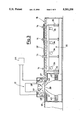
- FIG. 1 shows a schematic plan view of a cutting station provided in accordance with the present invention
- FIG. 2 shows a schematic cross section view along plane of cut II--II of FIG. 1,
- FIG. 3 shows a schematic cross section view along plane of cut III--III of FIG. 1,
- FIG. 4 shows a schematic partial cross section view along plane of cut IV--IV of FIG. 5 of a detail of the station of FIG. 1,
- FIG. 5 shows a schematic partial plan view of the detail of FIG. 4,
- FIG. 6 shows a schematic view of first cut programming means for the station of FIG. 1, and
- FIG. 7 shows a schematic view of second cut programming means for the station of FIG. 1.
- FIG. 1 shows schematically as a whole and indicated by reference number 10 a station in accordance with the present invention.
- Said station 10 comprises a supporting table 11 for a package, shown in broken lines and indicated by reference number 13, of blanks to be cut.
- table 11 run front clamps 12 and rear clamps 14 for movement of the package 13 under a first longitudinal cutter 15.
- a running conveyor 16 for example the roller type, conveys by means of the clamps 14 that which is deposited thereon to a transverse cutter 17 at the output of which a conveyor belt 18 conveys the cut blanks to unloading.
- Additional conveyors 19, 20 evacuate the scrap produced by the cutter 15 and the cutter 17 respectively.
- the longitudinal cutter 15 comprises mobile sorting fins 21 and 22 to turn aside through appropriate channels the scrap from the cutter to the conveyor 19 and initially composed of two conveyor belts 23 and 24 upstream and downstream of the cutter.
- the cutter has a pair of blades 26, 25 having opposed cutting edges for performance of a precision cut at the front and rear respectively of the package of blanks.
- the pair of blades 25, 26 is placed beneath the cutting table and the corresponding presser 27 is arranged above the blades and is movable vertically to press on the upper surfaces of the package to be cut.
- Such an original arrangement allows provision in the table 11 with ease slots 28, 29 for the clamp guides 12 and 14.
- the presser 27 can have bucking edges of metal or plastic such as ⁇ Vulcolan ⁇ . In the former case resistance to wear is greater while in the second case cuts are more accurate and this is useful when using sheets cut for splicing without rework.
- the clamps 12 and 14 are substantially moved together.
- the group of front clamps 12 and the group of rear clamps 14 are supported each by respective parallelogram frames 29, 30 moving by pistons 35, 36 from an operative position, shown in FIG. 2 for the frame 30, to a nonoperative position, shown in FIG. 2 for the frame 29.
- the frames 29, 30 comprise guides 31 and 32 each individually powered for horizontal running of a clamp by respective motors 33 and 34 as may be seen in FIG. 3 for the clamps 14.
- the transverse cutter 17 comprises two upper blades 37 and 38 always with opposed cutting edges for the precision cuts at the head and tail of the packages with the help of a presser with fixed counterblade 39.
- the cutter 17 comprises movable sorting fins 40 and 41 to turn aside with appropriate channels the scrap from the cutter to a conveyor 20 initially made up of two conveyor belts 42 and 43 upstream and downstream of the cutter.
- control device 44 e.g. with microprocessor, of the known art and therefore not further shown or described since it is readily immaginable by those skilled in the art especially in the light of the following description of its operation.
- control device 44 is connected also to photoelectric cell sensors 45 and 46 and to position encoders 47, 48 positioned upstream and downstream of the cutter 17 for purposes which are clarified below.
- FIGS. 4 and 5 show in greater detail a clamp, e.g. a gripping clamp 12, the clamp 14 being of the same design.
- the clamp comprises a slide 49 for running on the guide 31, by the above mentioned motor 33, and a head 50 comprising an element with cam sliding by means of a pin 52 in a slot 53 under the effect of a piston 54 to bring one gripping end, advantageously provided like a gripping roller generally in the form of a drum, from a nonoperative position, shown in unbroken lines in FIG. 4, to a gripping position on a package 13, shown in broken lines in FIG. 4, against a lower stop 57.
- the station 10 comprises in addition means 56 sending signals 58 to the device 44 to allow programming of the station along a particular series of cuts on a package.
- said means 56 can be part of a viewing or laser scanning system or the like for automatic, semiautomatic or manual programming of the position of the cutting sequence.
- a package of wood blanks to be cut is fed onto the table 11 manually or by conveyor belt of the known art and therefore not shown.
- the control system 44 then raises the clamps 12 by operation of the pistions 35 and advances them with the motors 33 until they are even with the edge of the package and then lowers their gripping end 55. In this manner the package is firmly held by the clamps which arrange it under the cut-setting means 56 while advancing.
- the clamps advance further to bring the package under the cutter 15 which is then commanded to perform in sequence all the preset longitudinal cuts. Between one cut and the next the clamps can advance independently of each other so as to perform also if necessary mutually oblique cuts.
- a first trimming cut is performed on the longitudinal edges of the package.
- the blade 26 is used and the scrap obtained is turned aside by movement of the fins 22 onto the belt 24 by which it is sent to the belt 19 to be evacuated from the station.
- the clamps 14 are raised and advanced to grip the sheared part emerging from the cutter 15.
- the clamps position the blank and the cutter is commanded to perform the cut.
- the piece cut downstream from the cutter 15 is then conveyed by the clamps 14 as shown by 13' in FIGS. 2 and 3 onto the roller conveyor 16 from which it is conveyed to the cutter 17.
- the photoelectric cell 45 detects the head of the package arriving at the cutter 17 and enables reading of the encoders 47, 48 to ascertain reaching of a predetermined transverse cutting position.
- the blade 38 is operated to trim the head of the blank and the corresponding scrap is evacuated by operation of the fins 40 and the belts 42 and 20.
- Advance of the blank 13' continues and the encoders and the photoelectric cells 45, 46 allow ascertaining of the position reached in each instant by the blank 13' so that the control device 44 continues to command operation of the cutter 17 to perform all the transverse cuts ascertained for the sheared piece 13'.
- the cut subparts emerge from the cutter 17 they are conveyed along the conveyor 18, for example to the storing, packing or similar means of the known art hence not shown. If in the cutting programme there are identified in the wood defects to be eliminated the cut piece containing a defect is evacuated by operation of the fin 41.
- the last transverse cut is performed by the blade 37 so as to trim the tail of the package of blanks 13' and the scrap is evacuated again by the fin 41.
- the longitudinal cutter 15 is operated to provide the next programmed cut so as to supply sequentially at the outlet another piece which will be conveyed to the cutter 17 after completion of the cutting of the preceding piece 13'. For this reason, during cutting of the piece 13' the clamps 14 are lowered to translate thereunder and return to the advanced position to grip the part of the package in simultaneous cut under the cutter 15.
- a new package can then be positioned on the table 11, from which the clamps 12 have withdrawn by operation of the pistons 35, and a new cutting program can be started. It is clear at this point that a station in accordance with the present invention can automatically cut the wood blanks both transversely and longitudinally and supply from the output of the tape 18 a sequence of accurately cut parts and from the belts 19, 20 wood scrap generated.
- the sequence of cuts to obtain cut parts as desired and to eliminate the parts containing defects can be set on the control device 44 by various procedures, each satisfying a certain type of requirement.
- FIG. 6 shows schematically a first possible embodiment, indicated by reference number 56', of the means 56 of FIG. 2.
- the embodiment 56' comprises a telecamera 59 sending the image of the package 13, placed on the table 11, to a processing unit 60 having a screen 61 reproducing the image.
- the operator can trace the lines 62 representing a cutting grid and adapted to the position of the defects and the shape of the package, for example with a keyboard 63 or another input device such as a mouse or a graphics pad.
- the operator can indicate which parts of the board are to be scrapped.
- FIG. 7 shows schematically a second alternate embodiment, indicated by 56", of the means 56 of FIG. 2.
- the embodiment 56" comprises means 65, 66 of controlled laser light emission to trace on the surface of the package to be cut longitudinal and transverse lines respectively.
- Said means can be for example provided by laser sources with cylindrical lens to project lines on the surface of the package and by powered operations for moving of the lines along the surface thereof.
- Said laser scanning devices are of the known art and accordingly are not described further since they are readily immaginable by those skilled in the art.
- Direction of the laser source is controlled by an electronic control device to which arrive setting signals emmited by manual controls 68 for the transverse lines and 69 for the longitudinal lines.
- the operator operates the controls 68 and 69 to position the lines even with the required cuts and send said data to the control device 44 for execution thereof.
- projection can be performed to obtain a single transverse line and a single longitudinal line at a time, representing two cuts during selection, or see the lines of the two cuts during selection and the lines corresponding to the cuts already selected.
- the operator can for example use a keyboard indicating device or the like or control the scrap in real time during cutting.
- the clamps 14 can also be provided running on fixed guides while giving up optimization of the processing times obtained by rapid return of the clamps 14 and the resulting performance of a new longitudinal cut while the transverse cuts on a piece 13' are being performed.
- the clamps 12 be retractable and disappearing in the table 11 so as to allow loading without obstacles of a package on the table 11, they too can be provided running on fixed guides.
- the cut presetting systems can be varied and even combined with each other compared with the above description as is readily immaginable to those skilled in the art.
- the telecamera 59 can be of the linear type and hence moving to scan the entire surface of the package, or with matrix. Viewing on the viewer can be total or divided in a sequence of partial images to save memory in the processing unit 60.
Landscapes
- Life Sciences & Earth Sciences (AREA)
- Engineering & Computer Science (AREA)
- Forests & Forestry (AREA)
- Mechanical Engineering (AREA)
- Wood Science & Technology (AREA)
- Manufacturing & Machinery (AREA)
- Chemical And Physical Treatments For Wood And The Like (AREA)
- Auxiliary Devices For And Details Of Packaging Control (AREA)
- Details Of Cutting Devices (AREA)
- Debarking, Splitting, And Disintegration Of Timber (AREA)
- Laser Beam Processing (AREA)
- Control Of Cutting Processes (AREA)
Applications Claiming Priority (2)
| Application Number | Priority Date | Filing Date | Title |
|---|---|---|---|
| ITMI910455A IT1249603B (it) | 1991-02-21 | 1991-02-21 | Stazione di taglio automatizzata per tranciati di legno |
| ITMI91A000455 | 1991-02-21 |
Publications (1)
| Publication Number | Publication Date |
|---|---|
| US5201258A true US5201258A (en) | 1993-04-13 |
Family
ID=11358688
Family Applications (1)
| Application Number | Title | Priority Date | Filing Date |
|---|---|---|---|
| US07/837,930 Expired - Fee Related US5201258A (en) | 1991-02-21 | 1992-02-20 | Automated cutting station for wood blanks |
Country Status (6)
| Country | Link |
|---|---|
| US (1) | US5201258A (fr) |
| EP (1) | EP0500181B1 (fr) |
| AT (1) | ATE138599T1 (fr) |
| DE (1) | DE69211029T2 (fr) |
| ES (1) | ES2088086T3 (fr) |
| IT (1) | IT1249603B (fr) |
Cited By (30)
| Publication number | Priority date | Publication date | Assignee | Title |
|---|---|---|---|---|
| US5251681A (en) * | 1992-06-05 | 1993-10-12 | Newman-Whitney | Method and apparatus for optimizing planer mill output |
| US5333526A (en) * | 1992-09-09 | 1994-08-02 | Heian Corporation | Running saw system |
| US5417265A (en) * | 1993-10-12 | 1995-05-23 | Newman Machine Company, Inc. | Infeed method and apparatus for a machining device |
| US6305259B1 (en) * | 1999-08-17 | 2001-10-23 | Flare International Sawmill Systems Ltd. | Log merchandiser |
| US6615100B1 (en) * | 1999-07-27 | 2003-09-02 | James Francis Urmson | Automated roof truss component saw |
| US6631006B2 (en) | 2001-05-17 | 2003-10-07 | Precision Automation, Inc. | System and method of marking materials for automated processing |
| US20050098004A1 (en) * | 2001-05-17 | 2005-05-12 | Precision Automation, Inc. | Systems and methods for automated material processing |
| US20060004478A1 (en) * | 2004-05-26 | 2006-01-05 | Dick Spencer B | Material handling systems |
| US20060000326A1 (en) * | 2004-05-26 | 2006-01-05 | Dick Spencer B | Material handling systems |
| US20060201582A1 (en) * | 2004-01-05 | 2006-09-14 | Edwards Jerry L | Lumber processing apparatus and method |
| US7171738B2 (en) | 2003-10-09 | 2007-02-06 | Precision Automation, Inc. | Systems for processing workpieces |
| US20070028730A1 (en) * | 2003-08-20 | 2007-02-08 | Sawyer Philip P | Apparatus and methods for double ended processing |
| US20070240547A1 (en) * | 2004-10-12 | 2007-10-18 | Dick Spencer B | Multi-step systems for processing workpieces |
| WO2007118932A1 (fr) * | 2006-04-18 | 2007-10-25 | Upm-Kymmene Wood Oy | Procede et equipement permettant de dimensionner et d'aligner une feuille de placage en bois |
| US20080009961A1 (en) * | 2006-02-24 | 2008-01-10 | Dick Spencer B | Gauge system |
| US7792602B2 (en) | 2006-08-22 | 2010-09-07 | Precision Automation, Inc. | Material processing system and a material processing method including a saw station and an interface with touch screen |
| US20110011497A1 (en) * | 2008-03-11 | 2011-01-20 | Padana Ag | Crossclipping and bundling system and method for veneer packets |
| US20110057384A1 (en) * | 2009-09-09 | 2011-03-10 | Raute Oyj | Method for the optimal alignment of veneer sheets at a lay-up station |
| US20130126489A1 (en) * | 2011-11-23 | 2013-05-23 | Highcon Systems Ltd | Cardboard-handling system and method |
| US8783140B2 (en) | 2009-06-09 | 2014-07-22 | Lean Tool Systems, Llc | Gauge system for workpiece processing |
| US20150153724A1 (en) * | 2013-12-02 | 2015-06-04 | George Platt | Method and system for consumer home projects ordering and fabrication |
| US9943975B2 (en) | 2012-02-01 | 2018-04-17 | Precision Automation, Inc. | Saw system for miter joints |
| US20180236681A1 (en) * | 2017-02-23 | 2018-08-23 | Boe Technology Group Co., Ltd. | Clearing device, operating method thereof, and cutting device |
| CN108501060A (zh) * | 2018-04-13 | 2018-09-07 | 盐城市协和机械有限公司 | 一种裁断机刀模与固定轴固定装置 |
| US20190054564A1 (en) * | 2016-03-09 | 2019-02-21 | Fit Things Nv | Cutting device and method |
| WO2019079728A1 (fr) * | 2017-10-20 | 2019-04-25 | Mitek Holdings, Inc. | Système automatisé de coupe et de distribution de bois de construction |
| US10739749B2 (en) | 2019-01-03 | 2020-08-11 | Kval, Inc. | System and method for manufacturing article dynamic measurement, tool selection and toolpath generation |
| US20200282585A1 (en) * | 2012-03-08 | 2020-09-10 | Marel Iceland Ehf | Cutting apparatus for cutting food items conveyed on a conveyor including at least one conveyor belt |
| CN111823331A (zh) * | 2020-07-07 | 2020-10-27 | 杨荣济 | 一种用于木材均匀切割分段的设备 |
| US11597045B2 (en) | 2019-08-12 | 2023-03-07 | Precision Automation, Inc. | Linear positioner |
Families Citing this family (7)
| Publication number | Priority date | Publication date | Assignee | Title |
|---|---|---|---|---|
| ES2067401B1 (es) * | 1993-03-17 | 1998-04-16 | Sanchez Bosque Jose Maria | Procedimiento, con su instalacion realizadora, para el corte optimizado de placas de marmol o piedra. |
| FR2779378B1 (fr) * | 1998-06-04 | 2000-08-04 | Roland Bigenwald | Procede de visualisation de defauts et de partage selectif d'une piece de bois et installation pour sa mise en oeuvre |
| EP1764414A1 (fr) | 2005-09-17 | 2007-03-21 | Icon Genetics AG | Particules virales de plantes comprenant une pluralité de protéines de fusion composées d'une protéine de capside d'un virus de plante, d'un peptide de liaison et d'une protéine recombinante et utilisation désdites particules virales pour la purification de protéines |
| FI119871B (fi) | 2006-02-15 | 2009-04-30 | Raute Oyj | Viiluleikkuri |
| DE102011009548A1 (de) * | 2011-01-19 | 2012-07-19 | Michael Weinig Ag | Maschine zum Bearbeiten von Werkstücken aus Holz, Kunststoff und dergleichen |
| DE202017104256U1 (de) * | 2017-07-18 | 2017-08-04 | Holz-Her Gmbh | Bearbeitungszentrum |
| CN112008804B (zh) * | 2020-09-24 | 2021-10-29 | 桃江县福丰木业有限公司 | 一种方便定位的细木工板锯边机 |
Citations (11)
| Publication number | Priority date | Publication date | Assignee | Title |
|---|---|---|---|---|
| US3780777A (en) * | 1971-10-06 | 1973-12-25 | Oliver Machinery Co | Defecting saw |
| US3931501A (en) * | 1973-08-30 | 1976-01-06 | National Association Of Furniture Manufacturers, Inc. | Apparatus and method for optimizing the yield of usable pieces from boards and the like |
| US4148344A (en) * | 1975-10-20 | 1979-04-10 | The Pack River Company | Portable sawmill |
| US4317397A (en) * | 1979-06-11 | 1982-03-02 | Schelling & Co. | System for the staggered division of planar workpieces |
| US4341135A (en) * | 1979-08-04 | 1982-07-27 | G. Siempelkamp Gmbh & Co. | Method of and apparatus for cutting a plate into small sections |
| US4381686A (en) * | 1980-05-21 | 1983-05-03 | Schelling & Co. | Apparatus for cutting and conveying planar workpieces |
| US4758960A (en) * | 1986-05-30 | 1988-07-19 | Krauss Und Reichert Gmbh & Co. Kg Spezialmaschinenfabrik | Method of cutting out faultless pattern pieces |
| US4794963A (en) * | 1987-10-05 | 1989-01-03 | Nemschoff Chairs, Inc. | Method and apparatus for optimizing the cutting of raw boards into product boards |
| US4947909A (en) * | 1989-02-14 | 1990-08-14 | Cae Machinery Ltd. | Process and apparatus for optimizing volume of boards cut from a log |
| US4977805A (en) * | 1986-04-10 | 1990-12-18 | Corley Manufacturing Company | Edging apparatus |
| US5042341A (en) * | 1988-03-11 | 1991-08-27 | Fagus-Grecon Greten Gmbh & Co. Kg | Marking station for timber |
Family Cites Families (8)
| Publication number | Priority date | Publication date | Assignee | Title |
|---|---|---|---|---|
| DE491788C (de) * | 1930-02-13 | August Fomm Fa | Papierschneidemaschinentisch | |
| DE832487C (de) * | 1950-06-04 | 1952-02-25 | Rosemarie Winkler Geb John | Verfahren und Vorrichtung zum paketweisen Beschneiden von Furnieren in Furnierbeschneidemaschinen |
| DE1207599B (de) * | 1965-01-07 | 1965-12-23 | Werner Pankoke Dipl Ing Dr | Furnierpaketschere |
| DE2037307A1 (de) * | 1970-07-28 | 1972-02-10 | Nebel D | Querschneider |
| JPS5326348B2 (fr) * | 1972-10-24 | 1978-08-01 | ||
| DK135030B (da) * | 1975-04-16 | 1977-02-28 | Viggo Larsen Maskinfabrik As | Apparat til skæring af stabler af finerer. |
| EP0151658A1 (fr) * | 1984-02-09 | 1985-08-21 | Carl Rückle Maschinenbau GmbH | Machine pour la coupe des côtés d'un paquet de placages et procédé exécuté par cette machine |
| DE8521276U1 (de) * | 1985-07-24 | 1985-11-07 | Carl Rückle Maschinenbau GmbH, 7302 Ostfildern | Schneidmaschine für aus Furnieren od. dgl. bestehende Pakete |
-
1991
- 1991-02-21 IT ITMI910455A patent/IT1249603B/it active IP Right Grant
-
1992
- 1992-02-18 ES ES92200449T patent/ES2088086T3/es not_active Expired - Lifetime
- 1992-02-18 EP EP92200449A patent/EP0500181B1/fr not_active Expired - Lifetime
- 1992-02-18 AT AT92200449T patent/ATE138599T1/de active
- 1992-02-18 DE DE69211029T patent/DE69211029T2/de not_active Expired - Fee Related
- 1992-02-20 US US07/837,930 patent/US5201258A/en not_active Expired - Fee Related
Patent Citations (11)
| Publication number | Priority date | Publication date | Assignee | Title |
|---|---|---|---|---|
| US3780777A (en) * | 1971-10-06 | 1973-12-25 | Oliver Machinery Co | Defecting saw |
| US3931501A (en) * | 1973-08-30 | 1976-01-06 | National Association Of Furniture Manufacturers, Inc. | Apparatus and method for optimizing the yield of usable pieces from boards and the like |
| US4148344A (en) * | 1975-10-20 | 1979-04-10 | The Pack River Company | Portable sawmill |
| US4317397A (en) * | 1979-06-11 | 1982-03-02 | Schelling & Co. | System for the staggered division of planar workpieces |
| US4341135A (en) * | 1979-08-04 | 1982-07-27 | G. Siempelkamp Gmbh & Co. | Method of and apparatus for cutting a plate into small sections |
| US4381686A (en) * | 1980-05-21 | 1983-05-03 | Schelling & Co. | Apparatus for cutting and conveying planar workpieces |
| US4977805A (en) * | 1986-04-10 | 1990-12-18 | Corley Manufacturing Company | Edging apparatus |
| US4758960A (en) * | 1986-05-30 | 1988-07-19 | Krauss Und Reichert Gmbh & Co. Kg Spezialmaschinenfabrik | Method of cutting out faultless pattern pieces |
| US4794963A (en) * | 1987-10-05 | 1989-01-03 | Nemschoff Chairs, Inc. | Method and apparatus for optimizing the cutting of raw boards into product boards |
| US5042341A (en) * | 1988-03-11 | 1991-08-27 | Fagus-Grecon Greten Gmbh & Co. Kg | Marking station for timber |
| US4947909A (en) * | 1989-02-14 | 1990-08-14 | Cae Machinery Ltd. | Process and apparatus for optimizing volume of boards cut from a log |
Cited By (57)
| Publication number | Priority date | Publication date | Assignee | Title |
|---|---|---|---|---|
| US5251681A (en) * | 1992-06-05 | 1993-10-12 | Newman-Whitney | Method and apparatus for optimizing planer mill output |
| US5333526A (en) * | 1992-09-09 | 1994-08-02 | Heian Corporation | Running saw system |
| US5417265A (en) * | 1993-10-12 | 1995-05-23 | Newman Machine Company, Inc. | Infeed method and apparatus for a machining device |
| US6615100B1 (en) * | 1999-07-27 | 2003-09-02 | James Francis Urmson | Automated roof truss component saw |
| US6305259B1 (en) * | 1999-08-17 | 2001-10-23 | Flare International Sawmill Systems Ltd. | Log merchandiser |
| US6631006B2 (en) | 2001-05-17 | 2003-10-07 | Precision Automation, Inc. | System and method of marking materials for automated processing |
| US20050098004A1 (en) * | 2001-05-17 | 2005-05-12 | Precision Automation, Inc. | Systems and methods for automated material processing |
| US20070028730A1 (en) * | 2003-08-20 | 2007-02-08 | Sawyer Philip P | Apparatus and methods for double ended processing |
| US7835808B2 (en) | 2003-08-20 | 2010-11-16 | Precision Automation, Inc. | Method and apparatus for processing material |
| US20090100974A1 (en) * | 2003-08-20 | 2009-04-23 | Sawyer Philip P | Method and apparatus for processing material |
| US7171738B2 (en) | 2003-10-09 | 2007-02-06 | Precision Automation, Inc. | Systems for processing workpieces |
| US20060201582A1 (en) * | 2004-01-05 | 2006-09-14 | Edwards Jerry L | Lumber processing apparatus and method |
| US7347232B2 (en) * | 2004-01-05 | 2008-03-25 | Edwards Jerry L | Lumber processing apparatus and method |
| US20060000326A1 (en) * | 2004-05-26 | 2006-01-05 | Dick Spencer B | Material handling systems |
| US7168353B2 (en) | 2004-05-26 | 2007-01-30 | Frecision Automation, Inc. | Material handling systems |
| US7245981B2 (en) | 2004-05-26 | 2007-07-17 | Precision Automation, Inc. | Material handling system with saw and wheel drag mechanism |
| US20060004478A1 (en) * | 2004-05-26 | 2006-01-05 | Dick Spencer B | Material handling systems |
| US20070240547A1 (en) * | 2004-10-12 | 2007-10-18 | Dick Spencer B | Multi-step systems for processing workpieces |
| US20090105871A1 (en) * | 2004-10-12 | 2009-04-23 | Precision Automation, Inc. | Multi-step systems for processing workpieces |
| US20090103977A1 (en) * | 2004-10-12 | 2009-04-23 | Precision Automation, Inc. | Multi-step systems for processing workpieces |
| US20090105872A1 (en) * | 2004-10-12 | 2009-04-23 | Precision Automation, Inc. | Multi-step system for processing workpieces |
| US20090105870A1 (en) * | 2004-10-12 | 2009-04-23 | Precision Automation, Inc. | Multi-step systems for processing workpieces |
| US8117732B2 (en) | 2004-10-12 | 2012-02-21 | Precision Automation, Inc. | Multi-step systems for processing workpieces |
| US7966714B2 (en) | 2004-10-12 | 2011-06-28 | Precision Automation, Inc. | Multi-step systems for processing workpieces |
| US7483765B2 (en) | 2006-02-24 | 2009-01-27 | Precision Automation, Inc. | Gauge system |
| US20080009961A1 (en) * | 2006-02-24 | 2008-01-10 | Dick Spencer B | Gauge system |
| WO2007118932A1 (fr) * | 2006-04-18 | 2007-10-25 | Upm-Kymmene Wood Oy | Procede et equipement permettant de dimensionner et d'aligner une feuille de placage en bois |
| RU2423228C2 (ru) * | 2006-04-18 | 2011-07-10 | Упм-Кюммене Вуд Ой | Способ определения размеров и обрезания краев натурального шпона и оборудование для реализации способа |
| US7792602B2 (en) | 2006-08-22 | 2010-09-07 | Precision Automation, Inc. | Material processing system and a material processing method including a saw station and an interface with touch screen |
| US20090299519A1 (en) * | 2007-02-26 | 2009-12-03 | Precision Automation, Inc. | Gauge system |
| US20110011497A1 (en) * | 2008-03-11 | 2011-01-20 | Padana Ag | Crossclipping and bundling system and method for veneer packets |
| US9993935B2 (en) | 2008-03-11 | 2018-06-12 | Danzer Services Schweiz Ag | Crossclipping and bundling system and method for veneer packets |
| US8783140B2 (en) | 2009-06-09 | 2014-07-22 | Lean Tool Systems, Llc | Gauge system for workpiece processing |
| US9996072B2 (en) | 2009-06-09 | 2018-06-12 | Lean Tool Systems, Llc | Gauge system for workpiece processing |
| US20110057384A1 (en) * | 2009-09-09 | 2011-03-10 | Raute Oyj | Method for the optimal alignment of veneer sheets at a lay-up station |
| US9790045B2 (en) * | 2009-09-09 | 2017-10-17 | Raute Oyj | Method for the optimal alignment of veneer sheets at a lay-up station |
| US10427248B2 (en) * | 2011-11-23 | 2019-10-01 | Highcon Systems Ltd. | Cardboard-handling system and method |
| US20130126489A1 (en) * | 2011-11-23 | 2013-05-23 | Highcon Systems Ltd | Cardboard-handling system and method |
| US9346129B2 (en) * | 2011-11-23 | 2016-05-24 | Highcon Systems Ltd. | Cardboard-handling system and method |
| US9943975B2 (en) | 2012-02-01 | 2018-04-17 | Precision Automation, Inc. | Saw system for miter joints |
| US11883975B2 (en) * | 2012-03-08 | 2024-01-30 | Marel Iceland Ehf | Cutting apparatus for cutting food items conveyed on a conveyor including at least one conveyor belt |
| US20200282585A1 (en) * | 2012-03-08 | 2020-09-10 | Marel Iceland Ehf | Cutting apparatus for cutting food items conveyed on a conveyor including at least one conveyor belt |
| US10768609B2 (en) | 2013-12-02 | 2020-09-08 | George Platt | Method and system for consumer home projects ordering and fabrication |
| US9720401B2 (en) * | 2013-12-02 | 2017-08-01 | George Platt | Method and system for consumer home projects ordering and fabrication |
| US20150153724A1 (en) * | 2013-12-02 | 2015-06-04 | George Platt | Method and system for consumer home projects ordering and fabrication |
| WO2015084672A3 (fr) * | 2013-12-02 | 2015-10-08 | George Platt | Procédé et système permettant la commande et la fabrication de projets domestiques de consommateurs |
| US20190054564A1 (en) * | 2016-03-09 | 2019-02-21 | Fit Things Nv | Cutting device and method |
| US11839932B2 (en) * | 2016-03-09 | 2023-12-12 | Fit Things Nv | Cutting device and method |
| US20180236681A1 (en) * | 2017-02-23 | 2018-08-23 | Boe Technology Group Co., Ltd. | Clearing device, operating method thereof, and cutting device |
| US10569440B2 (en) * | 2017-02-23 | 2020-02-25 | Boe Technology Group Co., Ltd. | Clearing device, operating method thereof, and cutting device |
| US11691310B2 (en) | 2017-10-20 | 2023-07-04 | Mitek Holdings, Inc. | Automated lumber cutting and delivery system |
| WO2019079728A1 (fr) * | 2017-10-20 | 2019-04-25 | Mitek Holdings, Inc. | Système automatisé de coupe et de distribution de bois de construction |
| US12594686B2 (en) | 2017-10-20 | 2026-04-07 | Mitek Holdings, Inc. | Automated lumber cutting and delivery system |
| CN108501060A (zh) * | 2018-04-13 | 2018-09-07 | 盐城市协和机械有限公司 | 一种裁断机刀模与固定轴固定装置 |
| US10739749B2 (en) | 2019-01-03 | 2020-08-11 | Kval, Inc. | System and method for manufacturing article dynamic measurement, tool selection and toolpath generation |
| US11597045B2 (en) | 2019-08-12 | 2023-03-07 | Precision Automation, Inc. | Linear positioner |
| CN111823331A (zh) * | 2020-07-07 | 2020-10-27 | 杨荣济 | 一种用于木材均匀切割分段的设备 |
Also Published As
| Publication number | Publication date |
|---|---|
| ATE138599T1 (de) | 1996-06-15 |
| ES2088086T3 (es) | 1996-08-01 |
| EP0500181B1 (fr) | 1996-05-29 |
| EP0500181A2 (fr) | 1992-08-26 |
| ITMI910455A1 (it) | 1992-08-21 |
| ITMI910455A0 (it) | 1991-02-21 |
| DE69211029D1 (de) | 1996-07-04 |
| EP0500181A3 (en) | 1993-02-03 |
| DE69211029T2 (de) | 1997-01-16 |
| IT1249603B (it) | 1995-03-09 |
Similar Documents
| Publication | Publication Date | Title |
|---|---|---|
| US5201258A (en) | Automated cutting station for wood blanks | |
| US7077042B2 (en) | Three-side trimmer | |
| EP1464470B1 (fr) | Plaqueuse de chant de panneaux en bois avec dispositif optique et système informatique pour l'acquisition des profils des pièces | |
| US4700758A (en) | Device for trimming the edges of veneer | |
| US4606387A (en) | Machine and method for trimming a stack of veneers | |
| US4945797A (en) | Automated multiple rip saw feeding apparatus | |
| US4836074A (en) | Machine for cutting stacks of paper sheets and the like | |
| US5777880A (en) | Method and apparatus for correctively guiding a cutting device on a predetermined path along a sheet material | |
| US20090266211A1 (en) | Linear saw with stab-cut bevel capability | |
| US6422111B1 (en) | Combined grading and trimming method for sawmill | |
| CA2218171C (fr) | Systeme d'alimentation automatique | |
| CN115488976B (zh) | 一种竹材定段破竹粗铣连续化生产装置 | |
| US20040069106A1 (en) | Linear feed cutting apparatus and method | |
| US3498167A (en) | Automatic precision numerical controlled punching and shearing machine | |
| JP2000198097A (ja) | 小さなシ―ト材料積み重ね体を形成しかつ後続処理する方法 | |
| US7681610B2 (en) | Optimized planermill system and method | |
| JP2000198098A (ja) | 積み重ねたシ―ト状材料を切断する平面切断機 | |
| EP0785052A1 (fr) | Procédé et dispositif pour travailler un tronc d'arbre par déchiquetage | |
| US4449558A (en) | Method and apparatus for trimming wooden boards | |
| CA2447412A1 (fr) | Systeme de manutention d'articles de sciage | |
| US3694294A (en) | Splicing apparatus for splicing strip material,as film or magnetic tape | |
| US20030213531A1 (en) | Article scanning method and apparatus for computer-controlled sawing machines | |
| CN117136113A (zh) | 用于准备分割至少两个工件的准备方法、计算机程序产品、计算机可读的存储介质,以及板材分割设备 | |
| CN214924769U (zh) | 一种人造草坪自动裁边切割设备 | |
| US20250010508A1 (en) | Positioning of a Position-Variable Stop Means of a Slicing Device for Slicing Food |
Legal Events
| Date | Code | Title | Description |
|---|---|---|---|
| AS | Assignment |
Owner name: ANGELO CREMONA & FIGLIO S.P.A., A CORP. OF ITALY, Free format text: ASSIGNMENT OF ASSIGNORS INTEREST.;ASSIGNOR:CREMONA, LORENZO;REEL/FRAME:006019/0290 Effective date: 19920129 |
|
| FEPP | Fee payment procedure |
Free format text: PAYOR NUMBER ASSIGNED (ORIGINAL EVENT CODE: ASPN); ENTITY STATUS OF PATENT OWNER: SMALL ENTITY |
|
| FPAY | Fee payment |
Year of fee payment: 4 |
|
| REMI | Maintenance fee reminder mailed | ||
| LAPS | Lapse for failure to pay maintenance fees | ||
| FP | Lapsed due to failure to pay maintenance fee |
Effective date: 20010413 |
|
| STCH | Information on status: patent discontinuation |
Free format text: PATENT EXPIRED DUE TO NONPAYMENT OF MAINTENANCE FEES UNDER 37 CFR 1.362 |