US5203024A - Antenna selection diversity reception system - Google Patents
Antenna selection diversity reception system Download PDFInfo
- Publication number
- US5203024A US5203024A US07/691,295 US69129591A US5203024A US 5203024 A US5203024 A US 5203024A US 69129591 A US69129591 A US 69129591A US 5203024 A US5203024 A US 5203024A
- Authority
- US
- United States
- Prior art keywords
- antenna
- receive
- time slot
- assigned time
- receive level
- Prior art date
- Legal status (The legal status is an assumption and is not a legal conclusion. Google has not performed a legal analysis and makes no representation as to the accuracy of the status listed.)
- Expired - Lifetime
Links
Images


Classifications
-
- H—ELECTRICITY
- H04—ELECTRIC COMMUNICATION TECHNIQUE
- H04L—TRANSMISSION OF DIGITAL INFORMATION, e.g. TELEGRAPHIC COMMUNICATION
- H04L1/00—Arrangements for detecting or preventing errors in the information received
- H04L1/02—Arrangements for detecting or preventing errors in the information received by diversity reception
-
- H—ELECTRICITY
- H04—ELECTRIC COMMUNICATION TECHNIQUE
- H04B—TRANSMISSION
- H04B7/00—Radio transmission systems, i.e. using radiation field
- H04B7/02—Diversity systems; Multi-antenna system, i.e. transmission or reception using multiple antennas
- H04B7/04—Diversity systems; Multi-antenna system, i.e. transmission or reception using multiple antennas using two or more spaced independent antennas
- H04B7/08—Diversity systems; Multi-antenna system, i.e. transmission or reception using multiple antennas using two or more spaced independent antennas at the receiving station
- H04B7/0802—Diversity systems; Multi-antenna system, i.e. transmission or reception using multiple antennas using two or more spaced independent antennas at the receiving station using antenna selection
- H04B7/0805—Diversity systems; Multi-antenna system, i.e. transmission or reception using multiple antennas using two or more spaced independent antennas at the receiving station using antenna selection with single receiver and antenna switching
- H04B7/0808—Diversity systems; Multi-antenna system, i.e. transmission or reception using multiple antennas using two or more spaced independent antennas at the receiving station using antenna selection with single receiver and antenna switching comparing all antennas before reception
Definitions
- the present invention relates to a diversity receiver system and, in particular, relates to an antenna selection diversity receiver system for overcoming fading in radio communication system.
- receive level is subject to change because of fading, and the decrease of receive level causes the deterioration of signal quality.
- a number of diversity techniques have been proposed.
- an antenna selection diversity reception system is considered to be promising for a mobile telephone system in which a miniaturized receiver set with low power consumption is essential.
- FIG. 10 shows a prior antenna selection diversity receiver for a 3 channel TDM system (time division multiplex). That kind of prior art is shown in IEEE Global Communication Conference 1988, entitled “Performance Of a Novel Selection Diversity Technique In an Experimental TDMA System For Digital Portable Radio Communications", pages 26.2.1-26.2.5.
- the numerals 1 and 2 are receive antennas
- 3 is a selection switch
- 4 is a receiver/demodulator
- 5 is a frame synchronization circuit
- 6 is an antenna selection circuit
- 6-1 is a timing circuit
- 6-2 is a switch control circuit
- 6-3 is a receive level measurement circuit
- 6-4 and 6-5 are sample-hold circuits
- 6-6 is a comparator.
- the signal A1 in the antenna 1 and the signal A2 in the antenna 2 are switched by the selection switch 3, and the selected signal A1 or A2 is applied to the receiver/demodulator 4, which demodulates the receive signal.
- the demodulated signal is applied to the frame synchronization circuit 5 for the frame synchronization.
- the antenna selection circuit 6 receives the frame timing signal from the frame synchronization circuit 5, and recognizes the receive timing of an assigned burst slot to its own receive station.
- the selection switch 3 is switched just before that beginning of the signal burst slot of its own station so that the receive levels on two antennas are compared.
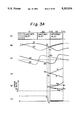
- FIG. 11 shows a switching process in the prior art, in which (a) shows a frame structure of a receive signal, which is a TDM signal with three channels in each frame.
- the third burst in each frame is the time slot assigned to the own station.
- the timing circuit 6-1 forwards to the receive level measurement circuit 6-3 a trigger signal at time t 1 which is just before the beginning of the assigned time slot so that the receive level R 1 at the antenna 1 is kept in the sample-hold circuit 6-4.
- the switch control circuit 6-2 switches the selection switch 3 to the other antenna 2 so that the receive level R 2 at the antenna 2 at time t 2 is kept in the sample-hold circuit 6-5.
- the comparator 6-6 compares R 1 with R 2 .
- the switch control circuit 6-2 selects the antenna which provides the higher receive level according to the result of the comparison, and keeps the switch 3 to receive the assigned time slot according to said comparison result.
- the switch control circuit 6-2 forwards the selection signal as shown in FIG. 11(c), in which the curve (1) indicates the selection of the antenna 1, and the curve (2) shows the selection of the antenna 2.
- R 1 is the level on the curve C1 just before the assigned time slot when the antenna 1 is selected
- R 2 is the receive level on the curve C2 just before the assigned time slot when the antenna 2 is selected.
- the receive level is compared before each assigned slot, and an antenna which provides the higher receive level is selected so that the receive level applied to the receiver/demodulator 4 is kept high to prevent data error.
- the prior art has the disadvantage that little diversity effect is obtained when fading rate is high, or the receive level changes rapidly.
- the receive level changes after the levels R 1 and R 2 are measured at time t 1 or t 2 the selected antenna does not provide the higher receive level.
- FIG. 11(d) and FIG. 11(e) show the above situation.
- the receive levels of the antennas 1 and 2 change as shown in the curves C1 and C2 in FIG. 11(d)
- the relations R 1 >R 2 are satisfied at time t 1 and t 2 , and therefore, the antenna 1 is selected for receiving the assigned burst signal.
- the receive levels are reversed, and the selected antenna provides the lower receive signal. In that case, an error rate is not improved by an antenna selection diversity system.
- the prior system is not useful when fading rate is high.
- an antenna selection diversity receiver system for TDM receive signal comprising; a plurality of antennas; a selection switch for selecting one of said antennas; a receiver/demodulator coupled with the selected antenna through said selection switch for providing demodulated receive signal and receive level; a frame synchronization circuit coupled with output of said receiver/demodulator for effecting frame synchronization of TDM signal; an antenna selection circuit coupled with output of said receiver/demodulator for receiving said receive level, and coupled with said selection switch for controlling said selection switch; wherein said antenna selection circuit comprises; a timing circuit coupled with said frame synchronization circuit for finding beginning of assigned time slot; first storage means for storing receive level of each antenna just before said assigned time slot; slope means for providing slope of said receive level of each antenna; second storage means for storing output of said slope means; prediction means for predicting receive signal quality of each antenna in said assigned time slot according to said receive level and said slope by using output of said first storage means and said second storage means; and a switch control circuit coupled with said timing circuit and said prediction means
- FIG. 1 is an operational flow chart of the first embodiment according to the present invention
- FIG. 2 is a block diagram of an antenna selection diversity receiver of the first embodiment according to the present invention.
- FIG. 3A shows the operation of the antenna selection in the first embodiment of the present invention
- FIG. 3B shows the modification of FIG. 3A
- FIG. 3C shows another modification of FIG. 3A
- FIG. 4 shows the transient response of a differentiation circuit
- FIG. 5 is an operational flow chart of the second embodiment according to the present invention.
- FIG. 6 is a block diagram of an antenna selection diversity receiver, of the second embodiment according to the present invention.
- FIG. 7A shows the operation of the antenna selection in the second embodiment of the present invention
- FIG. 7B is the modification of FIG. 7A
- FIG. 8 is a block diagram of an antenna selection diversity receiver of the third embodiment of the present invention.
- FIG. 9 shows the curves showing the effect of the present invention
- FIG. 10 is a block diagram of a prior diversity receiver
- FIG. 11 shows operation of the antenna selection in the prior art.
- FIG. 1 shows an operational flow chart of the first embodiment of the present invention
- FIG. 2 is a block diagram of the receiver according to the present invention.
- the same numerals in FIG. 2 as those in FIG. 10 show the same members.
- the numeral 7 in FIG. 2 is an antenna selection circuit
- 7-1 is a timing circuit
- 7-2 is a switch control circuit
- 7-3 is a receive level measurement circuit
- 7-4 is a receive level differentiation circuit
- 7-5, 7-6, 7-8 and 7-9 are sample hold circuits
- 7-7 is a differentiation circuit
- 7-10 is an error prediction circuit.
- the receive signal on the antenna 1 or 2 is applied to the receiver/demodulator 4 through the selection circuit 3.
- the demodulated signal in the receiver/demodulator 4 is applied to the frame synchronization circuit 5 for the frame synchronization.
- the antenna selection circuit 7 determines the assigned burst timing of the own station according to the frame timing signal from the frame synchronization circuit 5, and switches the selection switch 3 just before the beginning of the assigned slot so that the receive levels and the differentiating coeffecients of two antennas are measured.
- FIG. 3A shows the operation of the antenna selection.
- FIG. 3A(a) shows the frame structure of a receive signal, and is the same as FIG. 11(a).
- the symbol S1, S2 and S3 show slots in the frame, and it is assumed in the present embodiment that the slot S3 is the assigned slot, and S1 and S2 are other slots of other channels.
- the timing circuit 7-1 sends the receive level measurement circuit 7-3 a trigger signal at time t 1 which is just before the receive timing of the assigned time slot S3 so that the receive level R 1 by the selected antenna 1 at time t 1 is kept in the sample hold circuit 7-5. Simultaneously, the trigger signal is sent to the receive level differention circuit 7-4 so that the differentiating coefficient dR 1 which is obtained by differentiating the receive level of the antenna 1 by the differention circuit 7-7 is kept in the sample hold circuit 7-8 (102 in FIG. 1).
- the receive levels R 1 and R 2 just before the assigned burst slot concern the receive signal of the time slot S2, which differs from the assigned time slot S 3 .
- the receive level in another time slot S 2 is sufficient to predict the signal quality in the assigned time slot.
- the switch control circuit 7-2 switches the selection switch 3 to the other antenna 2 so that the receive level R 2 and the differentiating coefficient dR 2 at time t 2 are kept in the sample hold circuits 7-6 and 7-9, respectively (104 in FIG. 1).
- the measured four values R 1 , R 2 , dR 1 and dR 2 are applied to the error rate prediction circuit 7-10, which predicts the receive level and the error rate in the assigned time slot S3. For instance, when the receive level of the antennas 1 and 2 change as shown in the curves C1 and C2 in FIG. 3A(b), the differentiating coefficients of the receive levels C1 and C2 are shown by the curves D1 and D2 in FIG. 3A(c).
- the predicted receive levels r 1 and r 2 of each of the antennas, and the average error rates E 1 and E 2 of each of the antennas in the assigned time slot S3 which follows the measure time t 1 and t 2 are predicted as follows by using the values R 1 , R 2 , dR 1 and dR 2 (106 in FIG. 1).
- the theoretical error rate is; ##EQU2## where r 0 is the receive level which provides the normarized signal to noise ratio (E b /N 0 ) to be equal to 1 at an input of a detector, where E b is receive power for each signal bit, and N 0 is noise power density.
- the values r 1 , r 2 , E 1 and E 2 are predicted according to the above equations, and in the present embodiment, E 1 >E 2 is obtained as shown in FIG. A.3(d) and FIG. A.3(e) (108 in FIG. 1).
- the predicted error rate is applied to the switch control circuit 7-2, which selects the antenna 2 which provides the lower error rate, as shown in FIG. 3A(f) (112 in FIG. 1).
- the error rate when the assigned burst signal is received is kept low.
- the antenna 1 would be selected when E 1 ⁇ E 2 is satisfied.
- the measurement is carried out during the slot S2 which is just before the assigned time slot.
- the measurement is of course carried out during the slot S1 which is just before the assigned time slot.
- the curve of the receive level in FIG. 3A(b) is the same as that of FIG. 11(d).
- the antenna 1 is selected, and therefore, the error rate in the assigned burst timing is high.
- the present invention selects the antenna 2, the low error rate is obtained.
- the antenna is selected according to the predicted average error rate of each of the antennas calculated by using the receive level and the differentiating coefficient of the receive level of each of the antennas. Therefore, the antenna which provides the lower error rate in the assigned burst timing is selected even when the receive levels are reversed after the receive levels (R 1 , R 2 ) are measured. Thus, the effect of the diversity reception is improved.
- FIG. 3B shows the modification of the embodiment of FIG. 3A, and the same numerals in FIG. 3B show the same members as those in FIG. 3A.
- the feature of FIG. 3B is that the antenna is selected so that the receive level at the center of the assigned time slot or the average receive level during the slot is higher than that of the other antenna.
- the receive level (M 1 , M 2 ) at the center of the assigned time slot by each antenna is as follows.
- M i also presents the average receive level during the assigned time slot.
- the above equation (2A) is used for the selection of the antenna, instead of the equation (2). It should be noted in FIG. 3B that the receive levels M 1 and M 2 are predicted on the assumption that the receive level changes linearly.
- FIG. 3C shows another modification of the embodiment of FIG. 3A, and the same numerals in FIG. 3C show the same members as those in FIG. 3A.
- the feature of the FIG. 3C is that the antenna is selected depending upon the minimum receive level during the assigned time slot S3 so that the minumum receive level of the selected antenna is higher than the minumum receive level of the other antenna.
- the minimum receive level L 1 for the antenna 1, and the minimum receive level L 2 for the second antenna 2 are predicted as follows. ##EQU3##
- the antenna 2 is selected in the assigned time slot S3.
- FIGS. 4(a) and 4(b) show the same signal levels as those of FIGS. 3A(a) and 3A(b).
- the thick lines in FIG. 4(a) and FIG. 4(b) show the receive level provided at the output of the receiver/demodulator 4 in FIG. 2, and the differentiated value provided at the output of the differentiating circuit 7-7, respectively.
- the receive level at the output of the selection switch 3 has the uncontinuous step by the level (R 2 -R 1 ) Because of that step of the receive level, the differentiating waveform of the receive level has the transient response I in the form of negative impulse as shown in FIG. 4(b).
- the differentiating coefficient dR 2 ' measured just after the switching must include not only the desired differentiating coefficient dR 2 but also said transient response.
- the measured values of r 2 and E.sub. 2 in the equations (1) and (2) must also have the large error, and the correct antenna selection is impossible.
- the error rate E 1 which is predicted by using dR 1 at time t 1 would have large error since the value dR 1 itself would change until the assigned burst slot time due to rapid fading.
- FIGS. 5 and 6 show the second embodiment of the present invention for overcoming the above problem.
- FIG. 5 shows the operational flow diagram
- FIG. 6 shows a block diagram of a receiver.
- the numerals 7-2, 7-3, 7-5 and 7-6 are the same as those in FIG. 2, and 7-11 is a timing circuit, and 7-12 is a receive level difference measurement circuit.
- the numerals 7-13 and 7-14 are sample hold circuits, 7-15 and 7-16 are subtractors, and 7-17 is an error prediction circuit.
- the feature of the embodiment of FIG. 6 is to measure the receive level twice for each antenna, instead of the use of a differentiating circuit. The difference of two measured receive levels is used instead of the differenting coefficient.
- FIG. 7A shows the operation of the antenna selection in the second embodiment.
- FIG. 7A(a) shows the frame structure, which is the same as that of FIG. 3A(a).
- the timing circuit 7-11 forwards the receive level difference measurement circuit 7-12 a trigger signal at time t 3 which is a little before the beginning of the assigned burst signal so that the receive level R 3 at time t 3 in the antenna 1 is kept in the sample hold circuit 7-13.
- the switch control circuit 7-2 switches the selection switch 3 to the other antenna 2 at time t 4 which is immediate after the time t 3 so that the receive level R 4 in the antenna 2 is kept in the sample hold circuit 7-14.
- the antenna 1 is connected again, and the receive level R 1 in the antenna 1 at time t 1 is kept in the sample hold circuit 7-5. Finally, the antenna is again switched to the antenna 2, and the receive level R 2 in the antenna 2 at time t 2 is kept in the sample hold circuit 7-6. Thus, four receive levels R 1 through R 4 are obtained as shown in FIG. 7A(b) (152 in FIG. 5).
- the error prediction circuit 7-17 predicts the receive levels r 1 and r 2 for each of the antennas in the assigned time slot by using above values R 1 , R 2 , ⁇ R 1 and ⁇ R 2 as follows. ##EQU4##
- the values r 1 and r 2 thus obtained are shown in FIG. 7A(c), and those values are used for providing the error rates E 1 and E 2 in the equation (2), and the results are shown in FIG. 7A(d) (156 in FIG. 5).
- the switch control circuit 7-2 selects the antenna 2 as shown in FIG. 7A(e) (162 in FIG. 5). If E 1 ⁇ E 2 is satisfied, the antenna 1 is selected (160 in FIG. 5). Thus, the average error rate at the assigned time slot is kept low.
- FIG. 7A which uses a subtractor instead of a differentiation circuit may be combined with the concept of FIG. 3B which uses the receive level of each antenna at center of an assigned slot, and/or the concept of FIG. 3C which uses the minimum receive level of each antenna as criteria of the selection of antennas.
- FIG. 7A shows the concept of FIG. 7A, and the feature of the modification of FIG. 7B is to measure the receive level more than three times for each antenna, and the prediction of the receive level in an assigned slot is carried out non-linearly, while the embodiment of FIG. 7A predicts the receive level in the assigned time slot linearly.
- the measurement of receive level is carried out three times for each antenna, and the receive levels R 3 , R 5 and R 1 are obtained for the antenna 1, and the receive levels R 4 , R 6 and R 2 are obtained for the antenna 2.
- the receive level r 1 for the antenna 1 in an assigned slot, and the receive level r 2 for the antenna 2 in an assigned slot are predicted by using those measured receive levels. In case of three measured values, the predicted curve is quadratic.
- the average error rate is then calculated by using the equation (2), and the antenna selection is carried out so that the antenna which provides the lower average error rate is selected.
- the criteria of the selection of the antennas may be the receive level at the center of the assigned time slot of each antenna predicted by using more than three measured receive levels, and/or the minimum recieve level in the assigned burst slot predicted by using more than three measured receive levels.
- FIG. 8 is a block diagram of the third embodiment of the present invention.
- the feature of FIG. 8 is that the main portion of the embodiment of FIG. 6 is implemented by digital circuits.
- the receive levels R 1 through R 4 are kept in four sample hold circuits, on the other hand, in FIG. 8 embodiment, a single A/D converter 7-19 measures the receive levels at times t 1 through t 4 four times, and the measured values are stored in four registers 7-20 through 7-23.
- the registers 7-20 and 7-21 provide the receive levels R 1 and R 2 , respectively, and the digital subtractors 7-24 and 7-25 calculate the receive level differences ⁇ R 1 and ⁇ R 2 . Therefore, the receive level measurement circuit 7-18 in FIG. 8 is equivalent to the receive level measurement circuit 7-3 and receive level difference measurement circuit 7-12 in FIG. 6.
- the circuit 7-18 in FIG. 8 provide the values R 1 , R 2 , ⁇ R 1 , and ⁇ R 2 in digital form.
- the average error rates E 1 and E 2 are predicted as is the case of FIG. 6, and the antenna which provides the lower error rate is selected.
- the error rate prediction circuit 7-17 receives R 1 , R 2 , ⁇ R 1 and ⁇ R 2 in quantized digital form each having n bits.
- the error rate prediction circuit 7-17 can be implemented by a ROM (read only memory), which has address input terminals with 4n bits, and each address of the ROM stores the result of the comparison of E 1 and E 2 .
- the embodiment of FIG. 8 implements the process of R 1 through R 4 , E 1 and E 4 in digital form, and therefore, the circuit is implemented easily by using an IC.
- the digital subtractors 7-24 and 7-25 may be removed if the error rate prediction circuit 7-17 carries out the function of those subtractors. In that case, the error rate prediction circuit 7-17 receives R 1 through R 4 in quantized digital form. For instance, when R 1 through R 4 are applied to 4n bits of address terminals of a ROM, which stores the result of the comparison of E 1 and E 2 corresponding to each input values, the error rate prediction circuit 7-17, and the subtractors 7-24 and 7-25 are implemented by a single ROM.
- the present invention is applicable to a diversity receiver which has more than three antennas, although the above embodiments have two antennas.
- the calculation of the equations (1) and (2) is carried out for each antenna, and the antenna which provides the lowest error rate is selected.
- the receive level for each antenna is measured twice, and the calculation of the equation (4) is carried out for each antenna, and the result is inserted into the equation (2) so that the antenna which provides the lowest average error rate is selected.
- FIG. 9 shows the simulated performance curve which shows the effect of the present invention.
- the horizontal axis shows the fading frequency in Hz
- the vertical axis shows the diversity gain in dB, which is defined to be the input level difference between a diversity receiver and an ordinary (not diversity) receiver for providing an error rate of 1%.
- the solid line in FIG. 9 shows the curve of the present invention
- the dotted curve shows that of the prior art of FIG. 10.
- the diversity gain of the present invention is always higher than that of the prior art in any fading frequency.
- an antenna diversity receiver which provides an excellent diversity effect in high fading rate is obtained. Therefore, when a receiver is mounted on a moving mobile, an excellent diversity effect is obtained, and therefore, the present invention may be used in many mobile communication systems. The reception capability of a receiver is improved considerably by using the present invention.
- the present invention may replace a conventional diversity receiver which has two receivers selected at the output of detectors, and in that case, a receiver may be improved in size, and power consumption, since the present invention uses only one receiver.
Landscapes
- Engineering & Computer Science (AREA)
- Computer Networks & Wireless Communication (AREA)
- Signal Processing (AREA)
- Radio Transmission System (AREA)
- Time-Division Multiplex Systems (AREA)
Applications Claiming Priority (6)
| Application Number | Priority Date | Filing Date | Title |
|---|---|---|---|
| JP2114244A JPH0411415A (ja) | 1990-04-27 | 1990-04-27 | アンテナ選択ダイバーシチ受信方式 |
| JP2-114244 | 1990-04-27 | ||
| JP2-110517 | 1990-04-27 | ||
| JP2110517A JPH0410724A (ja) | 1990-04-27 | 1990-04-27 | アンテナ選択ダイバーシチ受信方法及びその方法による受信機 |
| JP2114245A JPH0411416A (ja) | 1990-04-27 | 1990-04-27 | アンテナ選択ダイバーシチ受信方式 |
| JP2-114245 | 1990-04-27 |
Publications (1)
| Publication Number | Publication Date |
|---|---|
| US5203024A true US5203024A (en) | 1993-04-13 |
Family
ID=27311755
Family Applications (1)
| Application Number | Title | Priority Date | Filing Date |
|---|---|---|---|
| US07/691,295 Expired - Lifetime US5203024A (en) | 1990-04-27 | 1991-04-25 | Antenna selection diversity reception system |
Country Status (5)
| Country | Link |
|---|---|
| US (1) | US5203024A (de) |
| EP (1) | EP0454585B1 (de) |
| JP (1) | JPH06103845B2 (de) |
| CA (1) | CA2041283C (de) |
| DE (1) | DE69103196T2 (de) |
Cited By (33)
| Publication number | Priority date | Publication date | Assignee | Title |
|---|---|---|---|---|
| US5369801A (en) * | 1992-09-25 | 1994-11-29 | Northern Telecom Limited | Antenna diversity reception in wireless personal communications |
| WO1995033312A1 (en) * | 1994-06-01 | 1995-12-07 | Motorola Inc. | A method for selecting two antennas |
| US5499397A (en) * | 1994-05-02 | 1996-03-12 | Motorola, Inc. | Switched antenna diversity algorithm employing received signal strength, phase errors and recovered clock |
| US5530925A (en) * | 1993-08-02 | 1996-06-25 | Harris Corporation | Intermediate frequency combiner for a radio communication system |
| US5530926A (en) * | 1993-10-04 | 1996-06-25 | Motorola, Inc. | Method for operating a switched diversity RF receiver |
| US5533027A (en) * | 1993-02-16 | 1996-07-02 | Telefonaktiebolaget Lm Ericsson | Digital fixed radio access system providing local mobility |
| US5557609A (en) * | 1993-12-01 | 1996-09-17 | Kabushiki Kaisha Toshiba | Switching apparatus for ATM |
| US5561673A (en) * | 1993-04-16 | 1996-10-01 | Matsushita Electric Industrial Co., Ltd. | Antenna switched diversity reciever |
| US5574750A (en) * | 1993-09-14 | 1996-11-12 | Pacific Communication Sciences, Inc. | Methods and apparatus for detecting a cellular digital packet data (CDPD) carrier |
| WO1997013378A3 (en) * | 1995-10-01 | 1997-06-05 | Geotek Communications Inc | Apparatus and method for determining and using channel state information |
| US5648992A (en) * | 1993-09-30 | 1997-07-15 | Rockwell Semiconductor Systems, Inc. | Multiple antenna home base for digital cordless telephones |
| US5842118A (en) * | 1996-12-18 | 1998-11-24 | Micron Communications, Inc. | Communication system including diversity antenna queuing |
| US5854808A (en) * | 1993-09-14 | 1998-12-29 | Pacific Communication Sciences | Methods and apparatus for detecting the presence of a prescribed signal in a channel of a communications system |
| US5960046A (en) * | 1996-12-03 | 1999-09-28 | Northern Telecom Limited | Preamble based selection diversity in a time division multiple access radio system |
| US6002672A (en) * | 1996-10-25 | 1999-12-14 | Nortel Networks Corporation | Diversity antenna selection |
| US6032033A (en) * | 1996-12-03 | 2000-02-29 | Nortel Networks Corporation | Preamble based selection diversity in a time division multiple access radio system using digital demodulation |
| US6115367A (en) * | 1997-08-05 | 2000-09-05 | Vlsi Technology, Inc. | Methods of analyzing a radio signal and methods of analyzing a personal handy-phone system radio signal |
| US6172970B1 (en) * | 1997-05-05 | 2001-01-09 | The Hong Kong University Of Science And Technology | Low-complexity antenna diversity receiver |
| US6289209B1 (en) | 1996-12-18 | 2001-09-11 | Micron Technology, Inc. | Wireless communication system, radio frequency communications system, wireless communications method, radio frequency communications method |
| US20010055959A1 (en) * | 1997-12-30 | 2001-12-27 | Qun Shen | Unified antenna diversity switching system for TDMA-based telephones |
| US6360088B1 (en) * | 1998-09-23 | 2002-03-19 | Ericsson Inc. | Antenna diversity switching system and method for selecting an antenna through a programmed evaluation |
| US6574461B1 (en) * | 1997-06-19 | 2003-06-03 | Telefonaktiebolaget Lm Ericsson (Publ) | Balanced diversity |
| US20030198302A1 (en) * | 2002-04-17 | 2003-10-23 | Wireless Interface Technologies, Inc. | DC-tolerant bit slicer and method |
| US20040106388A1 (en) * | 2002-12-03 | 2004-06-03 | Kyu Sang Ro | Method for processing radio waves, and audio system utilizing the method |
| US20050148306A1 (en) * | 2004-01-05 | 2005-07-07 | Hiddink Gerrit W. | Predictive method and apparatus for antenna selection in a wireless communication system |
| US20050153673A1 (en) * | 2004-01-14 | 2005-07-14 | Nec Corporation | Antenna-switching diversity receiver capable of switching antennas without deterioration of reception characteristic even when applied to the CDMA communication method |
| US20080085739A1 (en) * | 2002-09-20 | 2008-04-10 | Sanyo Electric Co., Ltd. | Adaptive array wireless communication apparatus, reception level display method, reception level adjusting method, reception level display program and reception level adjusting program |
| US20080240280A1 (en) * | 2007-04-02 | 2008-10-02 | Apacewave Technologies Corporation | Intelligent Iterative Switch Diversity |
| US20130017797A1 (en) * | 2011-07-13 | 2013-01-17 | Apple Inc. | Selective receive diversity in a mobile wireless device |
| US20140119344A1 (en) * | 2012-10-31 | 2014-05-01 | Qualcomm Incorporated | Adaptive allocation of idle slots based on error rate |
| US9271170B1 (en) | 2012-05-01 | 2016-02-23 | KCF Technologies Incorporated | Channel adaptation in sensor networks |
| US10291310B1 (en) * | 2018-04-09 | 2019-05-14 | Qualcomm Incorporated | Gap-based antenna measurement for antenna switch diversity |
| US10362636B2 (en) * | 2011-07-24 | 2019-07-23 | Ethertronics, Inc. | Antennas configured for self-learning algorithms and related methods |
Families Citing this family (24)
| Publication number | Priority date | Publication date | Assignee | Title |
|---|---|---|---|---|
| FI934052A7 (fi) * | 1993-09-15 | 1995-03-16 | Nokia Telecommunications Oy | Menetelmä radiovastaanotinyksikön toiminnan valvomiseksi sekä vastaanotinyksikkö |
| SE9402493L (sv) * | 1994-07-15 | 1996-01-16 | Ericsson Telefon Ab L M | Metod i en diversitetsmottagare |
| WO1996008089A1 (en) * | 1994-09-02 | 1996-03-14 | Nokia Telecommunications Oy | A method for improving connection quality in a cellular radio system and a receiver unit |
| US5628052A (en) * | 1994-09-12 | 1997-05-06 | Lucent Technologies Inc. | Wireless communication system using distributed switched antennas |
| WO1996012355A2 (en) * | 1994-10-17 | 1996-04-25 | Philips Electronics N.V. | A wireless digital communication system, a radio apparatus, a digital speaker, and a digital speaker controlling apparatus |
| GB2299734B (en) * | 1995-04-03 | 1999-10-27 | Motorola As | Method of switching in signal selecting system |
| EP0741466A3 (de) * | 1995-05-03 | 1996-12-18 | Hughes Aircraft Co | Verfahren und Vorrichtung zur adaptiven Antennenauswahl in einem mobilen Funkkommunikationssystem |
| EP0755131A3 (de) * | 1995-07-17 | 1999-05-06 | Hagenuk Gmbh | Vorrichtung zur Steuerung von Antennen |
| DE19530021C2 (de) * | 1995-07-17 | 1999-07-29 | Hagenuk Telecom Gmbh | Verfahren und Vorrichtung zur Steuerung von Antennen |
| JPH0964639A (ja) * | 1995-08-25 | 1997-03-07 | Uniden Corp | ダイバーシチ・アンテナ回路 |
| GB2308530B (en) * | 1995-12-21 | 2000-03-22 | Nokia Mobile Phones Ltd | Antenna selection control circuitry |
| GB2311693B (en) | 1996-03-29 | 2000-06-21 | Nokia Mobile Phones Ltd | Antenna selection control circuitry |
| US5903596A (en) * | 1996-05-16 | 1999-05-11 | Nakano; Takayuki | Spread spectrum demodulation unit |
| JP3380481B2 (ja) * | 1998-12-17 | 2003-02-24 | 松下電器産業株式会社 | 基地局装置 |
| US7024168B1 (en) | 1999-07-07 | 2006-04-04 | Telefonaktiebolaget L M Ericsson (Publ) | Controlled antenna diversity |
| GB0105019D0 (en) * | 2001-03-01 | 2001-04-18 | Koninkl Philips Electronics Nv | Antenna diversity in a wireless local area network |
| DE102006006266A1 (de) * | 2005-02-13 | 2006-08-24 | Lindenmeier, Heinz, Prof. Dr. Ing. | Anlage zum Empfang von digital modulierten Funksignalen zu einem Fahrzeug unter Verwendung von Antennendiversity |
| CN100362420C (zh) * | 2005-07-27 | 2008-01-16 | 大连理工大学 | 一种利用激光退火提高掺稀土氧化铝薄膜光学特性的方法 |
| GB0519582D0 (en) * | 2005-09-26 | 2005-11-02 | Cambridge Silicon Radio Ltd | Antenna diversity |
| EP2243225A4 (de) * | 2008-02-01 | 2014-08-20 | Apple Inc | System und verfahren für mehrantennen-broadcast/multicast-übertragung auf der basis des räumlichen multiplexens |
| US7933363B2 (en) | 2008-04-18 | 2011-04-26 | Cambridge Silicon Radio Limited | Polarization diversity |
| JP4820387B2 (ja) * | 2008-06-05 | 2011-11-24 | 日本放送協会 | ダイバーシティ受信装置 |
| CN102468888B (zh) * | 2010-11-08 | 2016-04-20 | 中兴通讯股份有限公司 | 接收天线分集故障检测的方法及装置 |
| FR3016260B1 (fr) * | 2014-01-06 | 2016-02-05 | Commissariat Energie Atomique | Recepteur multi-antennes a synchronisation temporelle commune aux differentes chaines de reception |
Citations (4)
| Publication number | Priority date | Publication date | Assignee | Title |
|---|---|---|---|---|
| US4613975A (en) * | 1983-08-26 | 1986-09-23 | Nec Corporation | Selective fading protection system |
| US4719649A (en) * | 1985-11-22 | 1988-01-12 | Sanders Associates, Inc. | Autoregressive peek-through comjammer and method |
| US4742567A (en) * | 1985-02-01 | 1988-05-03 | Toyota Jidosha Kabushiki Kaisha | Automobile antenna system |
| US4977616A (en) * | 1987-11-30 | 1990-12-11 | Motorola, Inc. | Antenna selection control circuit |
Family Cites Families (3)
| Publication number | Priority date | Publication date | Assignee | Title |
|---|---|---|---|---|
| JPS5732535B2 (de) * | 1975-02-17 | 1982-07-12 | ||
| US4513412A (en) * | 1983-04-25 | 1985-04-23 | At&T Bell Laboratories | Time division adaptive retransmission technique for portable radio telephones |
| CA1292584C (en) * | 1987-11-30 | 1991-11-26 | Henry Ludwig Kazecki | Antenna selection control circuit |
-
1991
- 1991-04-25 EP EP91401102A patent/EP0454585B1/de not_active Expired - Lifetime
- 1991-04-25 DE DE69103196T patent/DE69103196T2/de not_active Expired - Lifetime
- 1991-04-25 US US07/691,295 patent/US5203024A/en not_active Expired - Lifetime
- 1991-04-26 JP JP12296791A patent/JPH06103845B2/ja not_active Expired - Lifetime
- 1991-04-26 CA CA002041283A patent/CA2041283C/en not_active Expired - Lifetime
Patent Citations (4)
| Publication number | Priority date | Publication date | Assignee | Title |
|---|---|---|---|---|
| US4613975A (en) * | 1983-08-26 | 1986-09-23 | Nec Corporation | Selective fading protection system |
| US4742567A (en) * | 1985-02-01 | 1988-05-03 | Toyota Jidosha Kabushiki Kaisha | Automobile antenna system |
| US4719649A (en) * | 1985-11-22 | 1988-01-12 | Sanders Associates, Inc. | Autoregressive peek-through comjammer and method |
| US4977616A (en) * | 1987-11-30 | 1990-12-11 | Motorola, Inc. | Antenna selection control circuit |
Non-Patent Citations (4)
| Title |
|---|
| Afrashteh et al., "Performance of a Novel Selection Diversity Technique in an Experimental TDMA System for Digital Portable Radio Communications", IEEE Global Communication Conference 1988, pp. 26.2.1-26.2.5. |
| Afrashteh et al., Performance of a Novel Selection Diversity Technique in an Experimental TDMA System for Digital Portable Radio Communications , IEEE Global Communication Conference 1988, pp. 26.2.1 26.2.5. * |
| Yamao et al., "Predictive Antenna Selection Diversity (PASD) for TDMA Mobile Radio", Yasushi Yamao and Yoshinori Nagao, NTT Radio Communication Systems Laboratories, Mar. 1991, pp. 46.4.1-46.4.5. |
| Yamao et al., Predictive Antenna Selection Diversity (PASD) for TDMA Mobile Radio , Yasushi Yamao and Yoshinori Nagao, NTT Radio Communication Systems Laboratories, Mar. 1991, pp. 46.4.1 46.4.5. * |
Cited By (45)
| Publication number | Priority date | Publication date | Assignee | Title |
|---|---|---|---|---|
| US5369801A (en) * | 1992-09-25 | 1994-11-29 | Northern Telecom Limited | Antenna diversity reception in wireless personal communications |
| US5533027A (en) * | 1993-02-16 | 1996-07-02 | Telefonaktiebolaget Lm Ericsson | Digital fixed radio access system providing local mobility |
| US5561673A (en) * | 1993-04-16 | 1996-10-01 | Matsushita Electric Industrial Co., Ltd. | Antenna switched diversity reciever |
| US5530925A (en) * | 1993-08-02 | 1996-06-25 | Harris Corporation | Intermediate frequency combiner for a radio communication system |
| US5574750A (en) * | 1993-09-14 | 1996-11-12 | Pacific Communication Sciences, Inc. | Methods and apparatus for detecting a cellular digital packet data (CDPD) carrier |
| US5854808A (en) * | 1993-09-14 | 1998-12-29 | Pacific Communication Sciences | Methods and apparatus for detecting the presence of a prescribed signal in a channel of a communications system |
| US5719902A (en) * | 1993-09-14 | 1998-02-17 | Pacific Communication Sciences, Inc. | Methods and apparatus for detecting cellular digital packet data (CDPD) |
| US5648992A (en) * | 1993-09-30 | 1997-07-15 | Rockwell Semiconductor Systems, Inc. | Multiple antenna home base for digital cordless telephones |
| US5530926A (en) * | 1993-10-04 | 1996-06-25 | Motorola, Inc. | Method for operating a switched diversity RF receiver |
| US5557609A (en) * | 1993-12-01 | 1996-09-17 | Kabushiki Kaisha Toshiba | Switching apparatus for ATM |
| US5499397A (en) * | 1994-05-02 | 1996-03-12 | Motorola, Inc. | Switched antenna diversity algorithm employing received signal strength, phase errors and recovered clock |
| US5740526A (en) * | 1994-06-01 | 1998-04-14 | Bonta; Jeffrey D. | Method and apparatus for selecting two antennas from which to receive a communication signal |
| WO1995033312A1 (en) * | 1994-06-01 | 1995-12-07 | Motorola Inc. | A method for selecting two antennas |
| WO1997013378A3 (en) * | 1995-10-01 | 1997-06-05 | Geotek Communications Inc | Apparatus and method for determining and using channel state information |
| US6002672A (en) * | 1996-10-25 | 1999-12-14 | Nortel Networks Corporation | Diversity antenna selection |
| US6118773A (en) * | 1996-10-25 | 2000-09-12 | Nortel Networks Corporation | Impairment determination for a diversity antenna selection process |
| US6032033A (en) * | 1996-12-03 | 2000-02-29 | Nortel Networks Corporation | Preamble based selection diversity in a time division multiple access radio system using digital demodulation |
| US5960046A (en) * | 1996-12-03 | 1999-09-28 | Northern Telecom Limited | Preamble based selection diversity in a time division multiple access radio system |
| US6289209B1 (en) | 1996-12-18 | 2001-09-11 | Micron Technology, Inc. | Wireless communication system, radio frequency communications system, wireless communications method, radio frequency communications method |
| US6023610A (en) * | 1996-12-18 | 2000-02-08 | Micron Technology, Inc. | Communication system including diversity antenna queuing |
| US5842118A (en) * | 1996-12-18 | 1998-11-24 | Micron Communications, Inc. | Communication system including diversity antenna queuing |
| US6351630B2 (en) | 1996-12-18 | 2002-02-26 | Micron Technology, Inc. | Wireless communication system, radio frequency communications system, wireless communications method, radio frequency communications method, and backscatter radio frequency communications system |
| US6466771B2 (en) | 1996-12-18 | 2002-10-15 | Micron Technology, Inc. | Wireless communication system, radio frequency communications system, wireless communications method, radio frequency communications method, and backscatter radio frequency communications system |
| US6172970B1 (en) * | 1997-05-05 | 2001-01-09 | The Hong Kong University Of Science And Technology | Low-complexity antenna diversity receiver |
| US6574461B1 (en) * | 1997-06-19 | 2003-06-03 | Telefonaktiebolaget Lm Ericsson (Publ) | Balanced diversity |
| US6115367A (en) * | 1997-08-05 | 2000-09-05 | Vlsi Technology, Inc. | Methods of analyzing a radio signal and methods of analyzing a personal handy-phone system radio signal |
| US6847810B2 (en) * | 1997-12-30 | 2005-01-25 | Ericsson Inc. | Unified antenna diversity switching system for TDMA-based telephones |
| US20010055959A1 (en) * | 1997-12-30 | 2001-12-27 | Qun Shen | Unified antenna diversity switching system for TDMA-based telephones |
| US6360088B1 (en) * | 1998-09-23 | 2002-03-19 | Ericsson Inc. | Antenna diversity switching system and method for selecting an antenna through a programmed evaluation |
| US20030198302A1 (en) * | 2002-04-17 | 2003-10-23 | Wireless Interface Technologies, Inc. | DC-tolerant bit slicer and method |
| US8024002B2 (en) * | 2002-09-20 | 2011-09-20 | Kyocera Corporation | Adaptive array wireless communication apparatus, reception level display method, reception level adjusting method, reception level display program and reception level adjusting program |
| US20080085739A1 (en) * | 2002-09-20 | 2008-04-10 | Sanyo Electric Co., Ltd. | Adaptive array wireless communication apparatus, reception level display method, reception level adjusting method, reception level display program and reception level adjusting program |
| US20040106388A1 (en) * | 2002-12-03 | 2004-06-03 | Kyu Sang Ro | Method for processing radio waves, and audio system utilizing the method |
| US7068986B2 (en) * | 2002-12-03 | 2006-06-27 | Hyundai Motor Company | Method for processing radio waves, and audio system utilizing the method |
| US20050148306A1 (en) * | 2004-01-05 | 2005-07-07 | Hiddink Gerrit W. | Predictive method and apparatus for antenna selection in a wireless communication system |
| US7315733B2 (en) * | 2004-01-14 | 2008-01-01 | Nec Corporation | Antenna-switching diversity receiver capable of switching antennas without deterioration of reception characteristic even when applied to the CDMA communication method |
| US20050153673A1 (en) * | 2004-01-14 | 2005-07-14 | Nec Corporation | Antenna-switching diversity receiver capable of switching antennas without deterioration of reception characteristic even when applied to the CDMA communication method |
| US20080240280A1 (en) * | 2007-04-02 | 2008-10-02 | Apacewave Technologies Corporation | Intelligent Iterative Switch Diversity |
| US20130017797A1 (en) * | 2011-07-13 | 2013-01-17 | Apple Inc. | Selective receive diversity in a mobile wireless device |
| US8761701B2 (en) * | 2011-07-13 | 2014-06-24 | Apple Inc. | Selective receive diversity in a mobile wireless device |
| TWI495287B (zh) * | 2011-07-13 | 2015-08-01 | 蘋果公司 | 在行動式無線裝置中的選擇性接收分集 |
| US10362636B2 (en) * | 2011-07-24 | 2019-07-23 | Ethertronics, Inc. | Antennas configured for self-learning algorithms and related methods |
| US9271170B1 (en) | 2012-05-01 | 2016-02-23 | KCF Technologies Incorporated | Channel adaptation in sensor networks |
| US20140119344A1 (en) * | 2012-10-31 | 2014-05-01 | Qualcomm Incorporated | Adaptive allocation of idle slots based on error rate |
| US10291310B1 (en) * | 2018-04-09 | 2019-05-14 | Qualcomm Incorporated | Gap-based antenna measurement for antenna switch diversity |
Also Published As
| Publication number | Publication date |
|---|---|
| JPH06103845B2 (ja) | 1994-12-14 |
| EP0454585B1 (de) | 1994-08-03 |
| CA2041283C (en) | 1994-05-03 |
| EP0454585A1 (de) | 1991-10-30 |
| CA2041283A1 (en) | 1991-10-28 |
| DE69103196T2 (de) | 1995-02-23 |
| DE69103196D1 (de) | 1994-09-08 |
| JPH0645970A (ja) | 1994-02-18 |
Similar Documents
| Publication | Publication Date | Title |
|---|---|---|
| US5203024A (en) | Antenna selection diversity reception system | |
| CA2035167C (en) | Antenna selection diversity reception apparatus | |
| US5561673A (en) | Antenna switched diversity reciever | |
| US6128355A (en) | Selective diversity combining | |
| US4953197A (en) | Combination spatial diversity system | |
| US5291519A (en) | Digital mobile communications terminal equipment and receiving method therefor | |
| US5774810A (en) | Mobile radio communication device | |
| JP3070239B2 (ja) | 電子制御アンテナシステム | |
| JP2991170B2 (ja) | Cdma受信装置および方法 | |
| EP1044516B1 (de) | Tstd-sender mit ausgleich der antennensendeleistung und steuerverfahren dafür für basisstation in einem mobilen kommunikationssystem | |
| HK18797A (en) | TDMA communications system with adaptive equalization | |
| US6212371B1 (en) | Mobile wireless terminal and power controlling method | |
| JPH1188030A (ja) | 遅延線アンテナ・アレイ・システムおよびその方法 | |
| WO1996009701A1 (en) | Receiver path selection based on burst-type in a time division multiple access receiver | |
| EP0741466A2 (de) | Verfahren und Vorrichtung zur adaptiven Antennenauswahl in einem mobilen Funkkommunikationssystem | |
| US7095711B1 (en) | Communication method and apparatus for a radio local area network system using macrodiversity | |
| JPS6052132A (ja) | 移動局におけるダイバ−シチ受信方式 | |
| JP2005278017A (ja) | 無線通信装置 | |
| JPH02200020A (ja) | アンテナ切替ダイバーシチ方式 | |
| JPH088809A (ja) | ダイバーシティ受信機 | |
| JPH08251090A (ja) | 送信ダイバーシティ装置 | |
| JPH05167482A (ja) | スペースダイバシティ制御装置 | |
| JP2005065001A (ja) | ダイバーシチ受信装置 | |
| MXPA99010615A (en) | Selective diversity combining | |
| JPH1168631A (ja) | 無線受信機 |
Legal Events
| Date | Code | Title | Description |
|---|---|---|---|
| AS | Assignment |
Owner name: NIPPON TELEGRAPH AND TELEPHONS CORPORATION, JAPAN Free format text: ASSIGNMENT OF ASSIGNORS INTEREST.;ASSIGNOR:YAMAO, YASUSHI;REEL/FRAME:005686/0507 Effective date: 19910410 |
|
| STCF | Information on status: patent grant |
Free format text: PATENTED CASE |
|
| AS | Assignment |
Owner name: NTT MOBILE COMMUNICATIONS NETWORK, INC., JAPAN Free format text: ASSIGNMENT OF ASSIGNORS INTEREST;ASSIGNOR:NIPPON TELEGRAPH AND TELEPHONE CORPORATION;REEL/FRAME:006794/0615 Effective date: 19931130 |
|
| AS | Assignment |
Owner name: NIPON TELEGRAPH AND TELEPHONE CORPORATION, JAPAN Free format text: CHANGE OF ADDRESS;ASSIGNOR:NIPPON TELEGRAPH AND TELEPHONE CORPORATION;REEL/FRAME:008133/0724 Effective date: 19951018 |
|
| FPAY | Fee payment |
Year of fee payment: 4 |
|
| FPAY | Fee payment |
Year of fee payment: 8 |
|
| FPAY | Fee payment |
Year of fee payment: 12 |