US5210461A - Arc discharge lamp containing mechanism for extinguishing arc at end-of-life - Google Patents
Arc discharge lamp containing mechanism for extinguishing arc at end-of-life Download PDFInfo
- Publication number
- US5210461A US5210461A US07/837,790 US83779092A US5210461A US 5210461 A US5210461 A US 5210461A US 83779092 A US83779092 A US 83779092A US 5210461 A US5210461 A US 5210461A
- Authority
- US
- United States
- Prior art keywords
- envelope
- lamp
- arc discharge
- main body
- electrode filament
- Prior art date
- Legal status (The legal status is an assumption and is not a legal conclusion. Google has not performed a legal analysis and makes no representation as to the accuracy of the status listed.)
- Expired - Fee Related
Links
- 238000010891 electric arc Methods 0.000 title claims abstract description 40
- 206010011906 Death Diseases 0.000 title abstract description 12
- 239000000463 material Substances 0.000 claims abstract description 15
- 239000011521 glass Substances 0.000 claims description 12
- OAICVXFJPJFONN-UHFFFAOYSA-N Phosphorus Chemical compound [P] OAICVXFJPJFONN-UHFFFAOYSA-N 0.000 claims description 7
- 230000004323 axial length Effects 0.000 claims description 5
- 239000011324 bead Substances 0.000 claims description 4
- 238000000926 separation method Methods 0.000 claims description 3
- 238000010438 heat treatment Methods 0.000 abstract description 7
- 239000003708 ampul Substances 0.000 description 7
- 239000011248 coating agent Substances 0.000 description 7
- 238000000576 coating method Methods 0.000 description 7
- 238000000034 method Methods 0.000 description 5
- 238000004519 manufacturing process Methods 0.000 description 4
- QSHDDOUJBYECFT-UHFFFAOYSA-N mercury Chemical compound [Hg] QSHDDOUJBYECFT-UHFFFAOYSA-N 0.000 description 4
- 229910052753 mercury Inorganic materials 0.000 description 4
- 239000007789 gas Substances 0.000 description 3
- XKRFYHLGVUSROY-UHFFFAOYSA-N Argon Chemical compound [Ar] XKRFYHLGVUSROY-UHFFFAOYSA-N 0.000 description 2
- 239000000155 melt Substances 0.000 description 2
- 229910052751 metal Inorganic materials 0.000 description 2
- 239000002184 metal Substances 0.000 description 2
- 230000005855 radiation Effects 0.000 description 2
- 229910000497 Amalgam Inorganic materials 0.000 description 1
- 229910052786 argon Inorganic materials 0.000 description 1
- 230000015572 biosynthetic process Effects 0.000 description 1
- 239000004568 cement Substances 0.000 description 1
- 239000004020 conductor Substances 0.000 description 1
- 239000000470 constituent Substances 0.000 description 1
- 238000010276 construction Methods 0.000 description 1
- 238000002788 crimping Methods 0.000 description 1
- 230000014759 maintenance of location Effects 0.000 description 1
- 229910044991 metal oxide Inorganic materials 0.000 description 1
- 150000004706 metal oxides Chemical class 0.000 description 1
- 238000012986 modification Methods 0.000 description 1
- 230000004048 modification Effects 0.000 description 1
- 230000000284 resting effect Effects 0.000 description 1
- 230000000717 retained effect Effects 0.000 description 1
- 238000007790 scraping Methods 0.000 description 1
- 239000005361 soda-lime glass Substances 0.000 description 1
- WFKWXMTUELFFGS-UHFFFAOYSA-N tungsten Chemical compound [W] WFKWXMTUELFFGS-UHFFFAOYSA-N 0.000 description 1
Images

Classifications
-
- H—ELECTRICITY
- H01—ELECTRIC ELEMENTS
- H01J—ELECTRIC DISCHARGE TUBES OR DISCHARGE LAMPS
- H01J61/00—Gas-discharge or vapour-discharge lamps
- H01J61/02—Details
- H01J61/04—Electrodes; Screens; Shields
- H01J61/06—Main electrodes
- H01J61/067—Main electrodes for low-pressure discharge lamps
- H01J61/0672—Main electrodes for low-pressure discharge lamps characterised by the construction of the electrode
-
- H—ELECTRICITY
- H01—ELECTRIC ELEMENTS
- H01J—ELECTRIC DISCHARGE TUBES OR DISCHARGE LAMPS
- H01J5/00—Details relating to vessels or to leading-in conductors common to two or more basic types of discharge tubes or lamps
- H01J5/50—Means forming part of the tube or lamps for the purpose of providing electrical connection to it
- H01J5/54—Means forming part of the tube or lamps for the purpose of providing electrical connection to it supported by a separate part, e.g. base
-
- H—ELECTRICITY
- H01—ELECTRIC ELEMENTS
- H01J—ELECTRIC DISCHARGE TUBES OR DISCHARGE LAMPS
- H01J5/00—Details relating to vessels or to leading-in conductors common to two or more basic types of discharge tubes or lamps
- H01J5/50—Means forming part of the tube or lamps for the purpose of providing electrical connection to it
- H01J5/54—Means forming part of the tube or lamps for the purpose of providing electrical connection to it supported by a separate part, e.g. base
- H01J5/58—Means for fastening the separate part to the vessel, e.g. by cement
- H01J5/60—Means for fastening the separate part to the vessel, e.g. by cement for fastening by mechanical means
-
- H—ELECTRICITY
- H01—ELECTRIC ELEMENTS
- H01J—ELECTRIC DISCHARGE TUBES OR DISCHARGE LAMPS
- H01J61/00—Gas-discharge or vapour-discharge lamps
- H01J61/02—Details
-
- H—ELECTRICITY
- H01—ELECTRIC ELEMENTS
- H01J—ELECTRIC DISCHARGE TUBES OR DISCHARGE LAMPS
- H01J61/00—Gas-discharge or vapour-discharge lamps
- H01J61/70—Lamps with low-pressure unconstricted discharge having a cold pressure < 400 Torr
Definitions
- This invention relates to the field of low-pressure arc discharge lamps. More particularly, the invention relates to low-pressure arc discharge lamps, such as subminiature fluorescent lamps, having a structure or device which renders the lamp inoperable at the end of its useful life.
- end-of-life and end of the useful life of a low-pressure arc discharge lamp are defined as that time when the electron-emissive material on one electrode filament has been depleted causing the arc discharge to destroy the filament and/or strike other parts of the electrode mount structure.
- Low-pressure arc discharge lamps such as fluorescent lamps, are well known in the art and typically include a pair of electrodes made of a coil of tungsten wire upon which is deposited a coating of an electron-emissive material consisting of alkaline metal oxides (BaO, CaO, SrO) to lower the work function of the cathode and thus improve lamp efficiency.
- an electron-emissive material consisting of alkaline metal oxides (BaO, CaO, SrO) to lower the work function of the cathode and thus improve lamp efficiency.
- the cathode fall voltage is typically about 13 volts.
- the cathode fall voltage rises by 100 volts or more.
- the lamp may continue to operate with the additional power being deposited at the lamp electrode region.
- a lamp which normally operates at 0.1 amp would deposit 0.65 watt at each electrode during normal operation.
- the depleted electrode may consume 7.5 watts due to the increase in cathode fall voltage. This extra power can lead to excessive local heating of the lamp and fixture.
- Low-pressure arc discharge lamps especially those designed for operation at high current (1.5 amp) loading, such as very high output (VHO) lamps, sometimes fail by causing the fracture of the glass envelope. It is believed the sequence of events leading to such failures is as follows. At the end of the useful life of the lamp, the electron-emissive material on one of the electrode filaments becomes depleted. When such depletion occurs, the arc discharge strikes other components of the electrode structure and, in particular, the arc strikes the electrical leads supporting the electrode structure. The electrical leads are heated by the arc to the point where the wires soften and bend. Subsequently, the electrical leads and the electrode structure sag and come in contact with the glass envelope. The severe heat generated by the arc and the heated electrode structure causes the glass envelope to fracture.
- VHO very high output
- U.S. Pat. No. 3,265,917 which issued to Ray on Aug. 9, 1966, discloses a structure comprising a wire or conductive coating electrically connected to the inside portion of the electrode structure and extending to a thin-walled portion of the glass stem press.
- the arc strikes and follows the conductive path reaching the thin-walled portion of the stem press.
- the heat generated by the arc and the heated conductor softens and melts the thin wall of the stem press to the point where the hermetic seal is lost.
- the introduction of the external atmosphere into the lamp extinguishes the arc discharge and renders the lamp inoperable.
- U.S. Pat. No. 4,105,910 which issued to Evans on Aug. 8, 1978, discloses a structure providing for an auxiliary source of amalgam and for end-of-life extinguishment of the arc.
- This structure comprises a coating of a suitable amalgamative metal on portions of the stem press and the inside lead-in wire about the point where the lead-in wire emerges from the stem press.
- U.S. Pat. No. 4,495,440 which issued to Schlitt et al, discloses an arc-extinguishing ampul mounted on each electrode structure.
- the ampul comprises a thin-walled glass body enclosing an arc-extinguishing gas, at least one electrically conductive support wire, and a heat-conductive coating covering the outer surface of the ampul and portions of the support wire.
- the arc discharge is attracted to the ampul by the support wire.
- the heat of the arc softens and melts the ampul to the point where the arc-extinguishing gas within the ampul escapes and renders the lamp inoperable without loss of the lamp's hermetic seal.
- an arc discharge lamp comprising a light-transmissive envelope having a tubular-shaped main body and a press seal disposed at each end of the main body.
- the main body of the envelope has an internal diameter and contains a fill material for supporting a low pressure discharge.
- a layer of phosphor is disposed on a surface within the main body of the envelope.
- An electrode filament including a pair of electrode filament ends is located in each end of the main body. Each electrode filament end is in a contiguous relationship with an inside surface of the envelope.
- the arc discharge lamp further includes a pair of electrical leads attached to each electrode filament and sealed within a respective press seal.
- each electrode filament has an axial length greater than the internal diameter of the envelope.
- the axial length of the electrode filament is equal to about 7 mm and the internal diameter of the envelope is equal to about 5 mm.
- each pair of electrical leads includes a glass bead formed thereon for maintaining separation of said said electrical leads.
- the arc discharge lamp further includes an insulative base member disposed at each end of the lamp.
- Each of the base members surrounds a respective press seal and a portion of the tubular-shaped main body of the envelope.
- the base member extends axially from the press seal and beyond the center of a respective electrode filament.
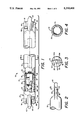
- FIG. 1 is a plan view, partially in cross section, of one embodiment of an arc discharge lamp in accordance with the present invention
- FIG. 2 is a partial view, partially in cross section, of the arc discharge lamp of FIG. 1 showing one of the press seals;
- FIG. 3 is an end view of the fluorescent lamp of FIG. 1;
- FIG. 4 is a cross-sectional view of the fluorescent lamp of FIG. 1 taken along the lines 4--4 of FIG. 1;
- FIG. 5 is a plan view of a mount structure for use in the arc discharge lamp of FIG. 1;
- FIG. 6 is a plan view, partially in cross section, of another embodiment of an arc discharge lamp in accordance with the present invention.
- FIG. 7 is an end view of the arc discharge lamp of FIG. 6;
- FIG. 8 is a partial view of the arc discharge lamp of FIG. 6 showing one of the lamp base members surrounding one of the press seals and a portion of the main body of the lamp;
- FIG. 9 is a cross-sectional view of the fluorescent lamp taken along the lines 9--9 in FIG. 8.
- Lamp 10 generally includes a tubular-shaped light-transmissive envelope 12 having a tubular-shaped main body.
- Envelope 12 is typically fabricated of soda lime glass and, by the way of example, can have an outside diameter on the order of about 0.18 inch to 0.27 inch and a length in the range of 4-20 inches.
- An electrode filament 14 is mounted in each end of envelope 12. Electrical leads 16 and 18 are connected to filament 14 and extend through a press seal 20. A glass bead 38 formed on electrical leads 16 and 18 insures that a predetermined separation between the electrical leads is maintained during formation of the press seal.
- the opposite end of the lamp 10 is constructed in the same manner and includes a press seal 22.
- a mercury dispenser 24 at one end of the lamp is attached to electrical lead 16.
- the lamp 10 contains a fill material including mercury supplied from dispenser 24 and a rare gas such as argon at a low pressure (e.g., 5 torr).
- Lamp 10 may include an aperture 34 which is formed in layer 30 to direct light from lamp 10 in a preferred direction. As best shown in FIG. 1, the aperture 34 extends axially along a major portion of length of envelope 12 and has a uniform width. The width of aperture 34 depends on the desired radiation pattern from lamp 10.
- layer 30 comprises a reflective layer and a phosphor layer. The reflective layer is first applied to the inside surface of envelope 12 and then the phosphor layer is applied over the reflective layer. The reflective layer has a reflective inside surface. The reflective layer insures that light emitted from the lamp 10 is directed through aperture 34. In an alternative configuration, the reflective layer is removed in aperture 34 but a phosphor layer is applied to the entire inner surface of envelope 12.
- aperture 34 and the reflective layer are omitted.
- the phosphor layer is uniformly applied to the inside surface of envelope 12, and the lamp provides a uniform cylindrical radiation pattern.
- the press seals 20 and 22 each include a tubulation 40 generally positioned on an axis 42 of envelope 12 and flattened regions 44 and 46 on opposite sides of tubulation 40.
- Electrical lead 16 extends through and is sealed into flattened region 44
- electrical lead 18 extends through and is sealed into flattened region 46.
- Flattened regions 44 and 46 include generally flat surfaces 44a and 46a (FIG. 3), respectively, which are used for orientation of aperture 34. In a preferred embodiment, the surfaces 44a and 46a are oriented at 90° with respect to a line drawn through the center of aperture 34 and the axis 42 of the envelope 12.
- Electrical leads 16 and 18 extend from the end of press seal 20 for connection of the electrode filament 14 to a source of electrical energy.
- electrical leads 16 and 18 are bent on opposite sides of press seal 20 and extend along the surfaces of flattened regions 44 and 46 respectively.
- the leads 16 and 18 extend from the end of lamp 10 parallel to axis 42 and can be connected to leads from the electrical source in any convenient manner, such as by crimping.
- the press seals 20 and 22 can be provided with means for positioning the baseless lamp 10 of FIG. 1 along axis 42.
- the positioning means can comprise one or more detents 50 formed in the press seals 20 and 22.
- the detents 50 comprise a depression or groove in flattened regions 44 and 46. The groove is oriented with its sides perpendicular to the axis 42 of envelope 12.
- one detent 50 is provided on each side of each press seal.
- a detent 50 is located on the front of flattened region 46 and a detent (not shown) is located on the back of flattened region 44.
- the detents 50 can be replaced with projections which engage corresponding detents in the mounting hardware.
- each electrode filament 14 located between electrical leads 16 and 18 is coated with a quantity of electron-emissive material in order to lower the work function of the cathode and thus improve lamp efficiency.
- the electron-emissive material on one of the electrode filaments becomes depleted causing the cathode fall voltage to rise by 100 volts or more. If the external circuitry fails to limit the open circuit voltage across the lamp, the lamp may continue to operate with the additional power being deposited at the lamp cathode region. This extra power can lead to excessive local heating of the lamp and fixture.
- each electrode filament 14 is provided with a pair of ends 26 and 28 (FIG. 1), which extend toward and are in a contiguous relationship with an inside surface of the main body of envelope 12. During normal operation, the heating of electrode filament 14 is confined to those regions of the electrode filament located between electrical leads 16 and 18. Accordingly, little heat is conducted to the glass wall and operation of lamp 10 is unaffected.
- FIG. 5 illustrates a mount 36 used in fabricating lamp 10.
- Mount 36 includes filament 14 supported by electrical leads 16 and 18 which are maintained separated by a conventionally-known glass bead 38.
- a mercury dispenser 24 is shown secured to electrical lead 16. It is understood that if a dispenser is employed as a means of introducing mercury into the lamp, only one dispenser is required per lamp.
- the axial length D1 (FIG. 5) of electrode filament 14 is slightly greater than the internal diameter of envelope 12.
- electrode filament 14 would typically have a length D1 equal to about 7 mm.
- Lamp 10' includes an electrically insulating (e.g., plastic) base member 60 secured to each end of the lamp.
- Base member 60 is of unitary construction and includes a first portion 62 having a tubular outer shape and a second portion 64 having a flattened shape and protruding from first portion 62. As shown in FIG. 7, a pair of apertures 66 are located within flattened portion 64, each of which extends through flattened portion 64 and is designed for having a respective exteriorly projecting portion of an electrical lead 16, 18 pass therethrough. As further illustrated in FIG. 7, a groove 76 is formed in the terminal end of flattened portion 64 for each electrical lead 16, 18. Grooves 76 provide positioning and allow the electrical leads to be flush with the end of the base member.
- first base member portion 62 located adjacent flattened portion 64 defines therein an opening 68 (FIG. 9) which is designed for having press seal 20 securedly positioned therein.
- the other end 86 of first portion 62 of the base member defines therein a circular opening 88.
- End 86 is designed to surround that portion of the lamp envelope adjacent electrode mount structure 36 and, preferably, to extend along the lamp axis and beyond the center of electrode filament 14 by a length D2 (FIG. 6). Typically, distance D2 is equal to about 3/16 inch (4.75 mm). Extending the first base member portion 62 provides support to the lamp envelope in the event that the envelope cracks in the area immediately adjacent the electrode filament ends 26 and 28.
- At least one protruding segment 82 projects from an internal wall of first base member portion 62.
- Preferably two such segments are utilized and positioned in a diagonally-opposing relationship as best illustrated in FIG. 9.
- Each of these protruding segments is designed for being aligned with and subsequently located within a corresponding detent 50 of press seal 20, 22.
- the first portion 62 of base member 60 further includes flexure means 70 therein as illustrated in FIGS. 8 and 9 to enable this part of the base member to expand a predetermined amount during said positioning.
- Flexure means 70 is preferably in the form of two elongated slots 72 formed within first portion 62 to thus enable the first portion to expand outwardly during positioning of the press seal within the base member. The press seal is thus firmly positioned within base member 60 without the need for cement or the like.
- base member 60 further includes a plurality of channels 74 (FIGS. 6-8), each located on first portion 62 of the base member adjacent flattened portion 64.
- Each channel 74 is designed to have one of the terminal ends of a respective electrical lead 16, 18 inserted therein.
- each channel 74 includes a tapered portion 80 which facilitates positioning of the substantially annular (round) electrical leads therein.
- each channel further includes a narrowed portion formed by a pair of opposing bumps 78 separated a distance which is slightly smaller than the diameter of the electrical lead.
- each of the terminal ends of the electrical leads is secured to the base member in a locking relationship to thus prevent subsequent removal thereof during the positioning of each lamp end within a corresponding socket member (not shown). Such retention also serves to assist in maintaining the press seal of lamp 10' firmly within base member 60.
- a total of two channels are provided on each base member, one for each of the mentioned electrical leads.
- the arc discharge lamp contains an end-of-life structure which does not require the lamp to have a stem press mount.
- the end-of-life structure is economical and does not add additional manufacturing steps to the lamp process.
Landscapes
- Vessels And Coating Films For Discharge Lamps (AREA)
Priority Applications (4)
| Application Number | Priority Date | Filing Date | Title |
|---|---|---|---|
| US07/837,790 US5210461A (en) | 1992-02-18 | 1992-02-18 | Arc discharge lamp containing mechanism for extinguishing arc at end-of-life |
| CA002089314A CA2089314A1 (fr) | 1992-02-18 | 1993-02-11 | Lampe a decharge en arc, contenant un mecanisme servant a eteindre l'arc a la fin de la duree de vie |
| EP93102478A EP0556800B1 (fr) | 1992-02-18 | 1993-02-17 | Lampe à décharge à arc contenant une mécanisme d'extinction d'arc en fin de vie utile |
| DE69318200T DE69318200T2 (de) | 1992-02-18 | 1993-02-17 | Gasentladungslampe mit Löschmechanismus am Ende der Lebensdauer |
Applications Claiming Priority (1)
| Application Number | Priority Date | Filing Date | Title |
|---|---|---|---|
| US07/837,790 US5210461A (en) | 1992-02-18 | 1992-02-18 | Arc discharge lamp containing mechanism for extinguishing arc at end-of-life |
Publications (1)
| Publication Number | Publication Date |
|---|---|
| US5210461A true US5210461A (en) | 1993-05-11 |
Family
ID=25275437
Family Applications (1)
| Application Number | Title | Priority Date | Filing Date |
|---|---|---|---|
| US07/837,790 Expired - Fee Related US5210461A (en) | 1992-02-18 | 1992-02-18 | Arc discharge lamp containing mechanism for extinguishing arc at end-of-life |
Country Status (4)
| Country | Link |
|---|---|
| US (1) | US5210461A (fr) |
| EP (1) | EP0556800B1 (fr) |
| CA (1) | CA2089314A1 (fr) |
| DE (1) | DE69318200T2 (fr) |
Cited By (12)
| Publication number | Priority date | Publication date | Assignee | Title |
|---|---|---|---|---|
| US5296780A (en) * | 1992-03-20 | 1994-03-22 | Gte Products Corporation | Arc discharge lamp having cementless right-angle base members |
| EP0656642A1 (fr) * | 1993-12-02 | 1995-06-07 | Heraeus Noblelight GmbH | Lampe radiante |
| US5606218A (en) * | 1995-03-24 | 1997-02-25 | Osram Sylvania Inc. | Cold cathode subminiature fluorescent lamp |
| US5705887A (en) * | 1995-02-17 | 1998-01-06 | Osram Sylvania Inc. | Fluorescent lamp with end of life arc quenching structure |
| EP0872869A1 (fr) * | 1997-04-18 | 1998-10-21 | Osram Sylvania Inc. | Boítier pour culot de lampe |
| US6400097B1 (en) * | 2001-10-18 | 2002-06-04 | General Electric Company | Low wattage fluorescent lamp |
| US6533633B2 (en) * | 2000-07-14 | 2003-03-18 | Nec Corporation | Methods of manufacturing aperture fluorescent lamp and surface illuminator |
| US6653781B2 (en) | 2001-06-15 | 2003-11-25 | General Electric Company | Low pressure discharge lamp with end-of-life structure |
| KR100400615B1 (ko) * | 1995-02-17 | 2003-12-18 | 오스람 실바니아 인코포레이티드 | 수명종료시에아크를소멸시키는수단을구비한형광램프 |
| US20030234614A1 (en) * | 2002-06-12 | 2003-12-25 | Kenji Itaya | Arc tube with shortened total length, manufacturing method for arc tube, and low-pressure mercury lamp |
| US20040095059A1 (en) * | 2002-06-14 | 2004-05-20 | Laudano Joseph D. | Discharge lamp having overlaid fluorescent coatings and methods of making the same |
| CN101740306A (zh) * | 2008-11-26 | 2010-06-16 | 奥斯兰姆有限公司 | 具有寿终保护的荧光灯管和自镇流荧光灯及其制造方法 |
Families Citing this family (3)
| Publication number | Priority date | Publication date | Assignee | Title |
|---|---|---|---|---|
| DE9305977U1 (de) * | 1993-04-20 | 1993-08-12 | Patent-Treuhand-Gesellschaft für elektrische Glühlampen mbH, 81543 München | Zweiseitig gesockelte Niederdruckentladungslampe |
| US6211618B1 (en) * | 1999-04-27 | 2001-04-03 | Philips Electronics North America Corp. | Arc discharge lamp with bimetal strip for fast passive lamp failure |
| WO2000075959A1 (fr) * | 1999-06-08 | 2000-12-14 | Matsushita Electric Industrial Co., Ltd. | Lampe à fluorescence |
Citations (11)
| Publication number | Priority date | Publication date | Assignee | Title |
|---|---|---|---|---|
| US2957995A (en) * | 1956-12-31 | 1960-10-25 | Gen Electric | Instant start discharge lamp |
| US3215892A (en) * | 1962-12-04 | 1965-11-02 | Sylvania Electric Prod | Fail-safe electrode assembly for fluorescent lamps |
| US3265917A (en) * | 1963-12-31 | 1966-08-09 | Sylvania Electric Prod | Fail-safe arc discharge lamp with integral arc extinguishing means |
| US3534216A (en) * | 1969-04-01 | 1970-10-13 | Sylvania Electric Prod | Lamp base for electric gaseous discharge devices |
| US3993386A (en) * | 1975-09-02 | 1976-11-23 | Rowe Lacy A | Lamp energy saving spacer |
| US4048537A (en) * | 1976-06-04 | 1977-09-13 | Gte Sylvania Incorporated | Protective ultraviolet-transmitting sleeve for fluorescent lamp |
| US4105910A (en) * | 1976-04-23 | 1978-08-08 | Westinghouse Electric Corp. | Fluorescent lamp with an integral fail-safe and auxiliary-amalgam component |
| US4221453A (en) * | 1978-07-12 | 1980-09-09 | Fritz Wagener Gmbh | Fluorescent tube with socket capping |
| US4495440A (en) * | 1982-08-23 | 1985-01-22 | Gte Products Corporation | Arc-extinguishing ampul and fluorescent lamp having such ampul mounted on each electrode structure |
| US4603278A (en) * | 1984-02-16 | 1986-07-29 | Gte Products Corporation | Electric lamp with insulating base |
| US4752710A (en) * | 1986-01-06 | 1988-06-21 | Gte Products Corporation | Electric lamp with insulating base providing improved wire retention |
Family Cites Families (2)
| Publication number | Priority date | Publication date | Assignee | Title |
|---|---|---|---|---|
| US2424457A (en) * | 1944-09-30 | 1947-07-22 | Gen Electric | Gaseous electric discharge lamp |
| US4942330A (en) * | 1988-09-30 | 1990-07-17 | Gte Products Corporation | Lamp assembly utilizing shield and ceramic fiber mesh for containment |
-
1992
- 1992-02-18 US US07/837,790 patent/US5210461A/en not_active Expired - Fee Related
-
1993
- 1993-02-11 CA CA002089314A patent/CA2089314A1/fr not_active Abandoned
- 1993-02-17 EP EP93102478A patent/EP0556800B1/fr not_active Expired - Lifetime
- 1993-02-17 DE DE69318200T patent/DE69318200T2/de not_active Expired - Fee Related
Patent Citations (11)
| Publication number | Priority date | Publication date | Assignee | Title |
|---|---|---|---|---|
| US2957995A (en) * | 1956-12-31 | 1960-10-25 | Gen Electric | Instant start discharge lamp |
| US3215892A (en) * | 1962-12-04 | 1965-11-02 | Sylvania Electric Prod | Fail-safe electrode assembly for fluorescent lamps |
| US3265917A (en) * | 1963-12-31 | 1966-08-09 | Sylvania Electric Prod | Fail-safe arc discharge lamp with integral arc extinguishing means |
| US3534216A (en) * | 1969-04-01 | 1970-10-13 | Sylvania Electric Prod | Lamp base for electric gaseous discharge devices |
| US3993386A (en) * | 1975-09-02 | 1976-11-23 | Rowe Lacy A | Lamp energy saving spacer |
| US4105910A (en) * | 1976-04-23 | 1978-08-08 | Westinghouse Electric Corp. | Fluorescent lamp with an integral fail-safe and auxiliary-amalgam component |
| US4048537A (en) * | 1976-06-04 | 1977-09-13 | Gte Sylvania Incorporated | Protective ultraviolet-transmitting sleeve for fluorescent lamp |
| US4221453A (en) * | 1978-07-12 | 1980-09-09 | Fritz Wagener Gmbh | Fluorescent tube with socket capping |
| US4495440A (en) * | 1982-08-23 | 1985-01-22 | Gte Products Corporation | Arc-extinguishing ampul and fluorescent lamp having such ampul mounted on each electrode structure |
| US4603278A (en) * | 1984-02-16 | 1986-07-29 | Gte Products Corporation | Electric lamp with insulating base |
| US4752710A (en) * | 1986-01-06 | 1988-06-21 | Gte Products Corporation | Electric lamp with insulating base providing improved wire retention |
Cited By (18)
| Publication number | Priority date | Publication date | Assignee | Title |
|---|---|---|---|---|
| US5296780A (en) * | 1992-03-20 | 1994-03-22 | Gte Products Corporation | Arc discharge lamp having cementless right-angle base members |
| EP0656642A1 (fr) * | 1993-12-02 | 1995-06-07 | Heraeus Noblelight GmbH | Lampe radiante |
| KR100400615B1 (ko) * | 1995-02-17 | 2003-12-18 | 오스람 실바니아 인코포레이티드 | 수명종료시에아크를소멸시키는수단을구비한형광램프 |
| US5705887A (en) * | 1995-02-17 | 1998-01-06 | Osram Sylvania Inc. | Fluorescent lamp with end of life arc quenching structure |
| US5606218A (en) * | 1995-03-24 | 1997-02-25 | Osram Sylvania Inc. | Cold cathode subminiature fluorescent lamp |
| EP0872869A1 (fr) * | 1997-04-18 | 1998-10-21 | Osram Sylvania Inc. | Boítier pour culot de lampe |
| US6533633B2 (en) * | 2000-07-14 | 2003-03-18 | Nec Corporation | Methods of manufacturing aperture fluorescent lamp and surface illuminator |
| US6830354B2 (en) | 2000-07-14 | 2004-12-14 | Nec Lcd Technologies, Ltd. | Aperture fluorescent lamp, surface illuminator, manufacturing methods thereof, liquid crystal display device, and electronic device |
| US6890087B2 (en) | 2000-07-14 | 2005-05-10 | Nec Lcd Technologies, Ltd. | Aperture fluorescent lamp, surface illuminator, manufacturing methods thereof, liquid crystal display device, and electronic device |
| US6653781B2 (en) | 2001-06-15 | 2003-11-25 | General Electric Company | Low pressure discharge lamp with end-of-life structure |
| US6400097B1 (en) * | 2001-10-18 | 2002-06-04 | General Electric Company | Low wattage fluorescent lamp |
| US20030234614A1 (en) * | 2002-06-12 | 2003-12-25 | Kenji Itaya | Arc tube with shortened total length, manufacturing method for arc tube, and low-pressure mercury lamp |
| US7196462B2 (en) * | 2002-06-12 | 2007-03-27 | Matsushita Electric Industrial Co., Ltd. | Arc tube with shortened total length, manufacturing method for arc tube, and low-pressure mercury lamp |
| US20070132362A1 (en) * | 2002-06-12 | 2007-06-14 | Kenji Itaya | Arc tube with shortened total length, manufacturing method for arc tube, and low-pressure mercury lamp |
| US7423370B2 (en) | 2002-06-12 | 2008-09-09 | Matsushita Electric Industrial Co., Ltd. | Arc tube with shortened total length, manufacturing method for arc tube, and low-pressure mercury lamp |
| US20040095059A1 (en) * | 2002-06-14 | 2004-05-20 | Laudano Joseph D. | Discharge lamp having overlaid fluorescent coatings and methods of making the same |
| US6919676B2 (en) * | 2002-06-14 | 2005-07-19 | Voltarc Technologies Inc. | Discharge lamp having overlaid fluorescent coatings and methods of making the same |
| CN101740306A (zh) * | 2008-11-26 | 2010-06-16 | 奥斯兰姆有限公司 | 具有寿终保护的荧光灯管和自镇流荧光灯及其制造方法 |
Also Published As
| Publication number | Publication date |
|---|---|
| EP0556800B1 (fr) | 1998-04-29 |
| DE69318200D1 (de) | 1998-06-04 |
| EP0556800A1 (fr) | 1993-08-25 |
| CA2089314A1 (fr) | 1993-08-19 |
| DE69318200T2 (de) | 1999-01-14 |
Similar Documents
| Publication | Publication Date | Title |
|---|---|---|
| US5210461A (en) | Arc discharge lamp containing mechanism for extinguishing arc at end-of-life | |
| US5493167A (en) | Lamp assembly with shroud employing insulator support stops | |
| EP0596735A1 (fr) | Tube à arc comprenant une source d'amorcage | |
| CA1212985A (fr) | Ampoule d'extinction d'arc et lampe fluorescente munie d'une telle ampoule a chaque electrode | |
| US6870317B2 (en) | Gas discharge tube | |
| US4415829A (en) | Direct current operable arc lamp | |
| US5276379A (en) | Arc discharge lamp having cementless base members | |
| US4904900A (en) | Glow discharge lamp | |
| US7057345B2 (en) | Short arc discharge lamp and light source device | |
| US5296780A (en) | Arc discharge lamp having cementless right-angle base members | |
| KR100327698B1 (ko) | 전자방출 전극구체, 방전램프 및 방전램프장치 | |
| JP3400489B2 (ja) | 複合放電ランプ | |
| US4935664A (en) | Diffuse discharge lamp | |
| JP2004519077A (ja) | ガス入りアーク放電灯およびその製造方法 | |
| US5049785A (en) | Two contact, AC-operated negative glow fluorescent lamp | |
| US5218269A (en) | Negative glow discharge lamp having wire anode | |
| GB2079044A (en) | Fluorescent lighting system | |
| US5006762A (en) | Negative glow fluorescent lamp having discharge barrier | |
| US5039908A (en) | Tri-model thermal switch and preheat lamp containing same | |
| JP3293591B2 (ja) | シールドビーム形放電ランプ | |
| JP3782169B2 (ja) | 無電極放電ランプ | |
| US20020190647A1 (en) | Low pressure dicharge lamp with end-of-life structure | |
| EP0577275A1 (fr) | Lampe fluorescente | |
| JP2002543561A (ja) | アーク放電ランプ | |
| US5126630A (en) | Tri-model thermal switch and preheat lamp containing same |
Legal Events
| Date | Code | Title | Description |
|---|---|---|---|
| AS | Assignment |
Owner name: GTE PRODUCTS CORPORATION Free format text: ASSIGNMENT OF ASSIGNORS INTEREST.;ASSIGNORS:PAI, ROBERT Y.;HARADEN, THOMAS;HOUGH, HAROLD L.;REEL/FRAME:006025/0998 Effective date: 19920212 |
|
| FEPP | Fee payment procedure |
Free format text: PAYOR NUMBER ASSIGNED (ORIGINAL EVENT CODE: ASPN); ENTITY STATUS OF PATENT OWNER: LARGE ENTITY |
|
| FPAY | Fee payment |
Year of fee payment: 4 |
|
| REMI | Maintenance fee reminder mailed | ||
| LAPS | Lapse for failure to pay maintenance fees | ||
| FP | Lapsed due to failure to pay maintenance fee |
Effective date: 20010511 |
|
| STCH | Information on status: patent discontinuation |
Free format text: PATENT EXPIRED DUE TO NONPAYMENT OF MAINTENANCE FEES UNDER 37 CFR 1.362 |