US5228280A - Round baler having anti-wrapping core starter - Google Patents
Round baler having anti-wrapping core starter Download PDFInfo
- Publication number
- US5228280A US5228280A US07/811,073 US81107391A US5228280A US 5228280 A US5228280 A US 5228280A US 81107391 A US81107391 A US 81107391A US 5228280 A US5228280 A US 5228280A
- Authority
- US
- United States
- Prior art keywords
- roller
- conveyor
- transverse
- belts
- round baler
- Prior art date
- Legal status (The legal status is an assumption and is not a legal conclusion. Google has not performed a legal analysis and makes no representation as to the accuracy of the status listed.)
- Expired - Fee Related
Links
- 239000007858 starting material Substances 0.000 title claims abstract description 39
- 239000000463 material Substances 0.000 claims abstract description 44
- 230000015572 biosynthetic process Effects 0.000 claims abstract description 9
- 230000007246 mechanism Effects 0.000 claims description 9
- 230000009471 action Effects 0.000 claims description 7
- 210000003141 lower extremity Anatomy 0.000 claims 1
- 210000001364 upper extremity Anatomy 0.000 claims 1
- 230000002401 inhibitory effect Effects 0.000 abstract 1
- 238000010276 construction Methods 0.000 description 3
- 230000008901 benefit Effects 0.000 description 2
- 239000010813 municipal solid waste Substances 0.000 description 2
- 238000009825 accumulation Methods 0.000 description 1
- 238000013459 approach Methods 0.000 description 1
- 238000004140 cleaning Methods 0.000 description 1
- 230000012447 hatching Effects 0.000 description 1
- 238000000034 method Methods 0.000 description 1
- 238000012986 modification Methods 0.000 description 1
- 230000004048 modification Effects 0.000 description 1
- 230000008569 process Effects 0.000 description 1
- 230000000717 retained effect Effects 0.000 description 1
- 238000005096 rolling process Methods 0.000 description 1
- 239000000126 substance Substances 0.000 description 1
Images


Classifications
-
- A—HUMAN NECESSITIES
- A01—AGRICULTURE; FORESTRY; ANIMAL HUSBANDRY; HUNTING; TRAPPING; FISHING
- A01F—PROCESSING OF HARVESTED PRODUCE; HAY OR STRAW PRESSES; DEVICES FOR STORING AGRICULTURAL OR HORTICULTURAL PRODUCE
- A01F15/00—Baling presses for straw, hay or the like
- A01F15/07—Rotobalers, i.e. machines for forming cylindrical bales by winding and pressing
-
- A—HUMAN NECESSITIES
- A01—AGRICULTURE; FORESTRY; ANIMAL HUSBANDRY; HUNTING; TRAPPING; FISHING
- A01F—PROCESSING OF HARVESTED PRODUCE; HAY OR STRAW PRESSES; DEVICES FOR STORING AGRICULTURAL OR HORTICULTURAL PRODUCE
- A01F15/00—Baling presses for straw, hay or the like
- A01F15/07—Rotobalers, i.e. machines for forming cylindrical bales by winding and pressing
- A01F2015/078—Pressing chamber formed exclusively by flexible elements, e.g. belts
-
- A—HUMAN NECESSITIES
- A01—AGRICULTURE; FORESTRY; ANIMAL HUSBANDRY; HUNTING; TRAPPING; FISHING
- A01F—PROCESSING OF HARVESTED PRODUCE; HAY OR STRAW PRESSES; DEVICES FOR STORING AGRICULTURAL OR HORTICULTURAL PRODUCE
- A01F15/00—Baling presses for straw, hay or the like
- A01F15/07—Rotobalers, i.e. machines for forming cylindrical bales by winding and pressing
- A01F2015/0795—Pressing chamber with variable volume
-
- A—HUMAN NECESSITIES
- A01—AGRICULTURE; FORESTRY; ANIMAL HUSBANDRY; HUNTING; TRAPPING; FISHING
- A01F—PROCESSING OF HARVESTED PRODUCE; HAY OR STRAW PRESSES; DEVICES FOR STORING AGRICULTURAL OR HORTICULTURAL PRODUCE
- A01F15/00—Baling presses for straw, hay or the like
- A01F15/08—Details
- A01F15/18—Endless belts, rolls or the like
- A01F2015/183—Constructional details of belts of the press chamber
Definitions
- This invention relates to round balers and, more particularly, to mechanism for achieving more reliable starting of a bale core during each baling cycle while minimizing the tendency of crop materials to plug the machine and wrap around rotating components.
- the baling operation can proceed relatively smoothly once the initial start up phase has passed and it is only necessary for the bale core to continue wrapping itself with additional layers of material as such materials are picked up and introduced into the baling chamber.
- the start up or core forming stage can be troublesome, depending upon crop conditions, including the nature of the crop being baled and its moisture content.
- the fresh crop material may not tumble properly within the empty chamber and may thus fail to form the coiled up core in the desired manner; in other instances, the crop material may plug up the infeed region of the baler and/or become wrapped around rotating parts so completely that the operation must be halted and the troublesome materials cleaned out of the machine.
- it is an important object of the present invention is to provide improvements in the infeed region of a rotary baler which retain the benefits of a bale starter roller without its drawbacks.
- it is an important object of the present invention to provide an improved baler having more reliable starting characteristics in a wider variety of crop conditions and types than has heretofore been possible.
- the present invention contemplates providing the starter roller with a moving, essentially flat surface at the top of the roller where contact is normally made with the bale core so that, instead of having a complete cylindrical surface around which the loose crop materials can wrap, the materials are instead confronted with a platform-like surface that simply presents no opportunity for wrapping.
- the starter roller comprises an end roller of a conveyor assembly in which the roller is covered by the moving top stretch of an endless belt wrapped around the roller, the opposite end of the belt being wrapped around another transverse roller that is spaced a substantial distance forwardly out of the infeed region toward the front of the baler.
- the starter roller can still function to transmit driving rotational force to the coiling materials within the baling chamber and to support some of the weight of the bale core and forming bale as the baling cycle progresses
- the belt surfaces beside and around the roller prevent access to the roller itself by the crop materials. Thus, they are not permitted to wrap the roller and instead are conveyed on into the baling chamber where they belong.
- the conveyor extends in a generally horizontal manner out from the infeed region and below an upper and forward guide roll under which some of the bale forming belts of the machine are looped. Consequently, loose material that tends to be drawn downwardly toward the starter roller by a downwardly moving stretch of the belts around the guide roll is also denied access to the starter roller and is instead deposited on the upper, inwardly moving stretch of the conveyor to be delivered into the baling chamber.
- Other loose materials which are continuously discharged from areas of entrapment within the front portion of the baler by powered cleanout devices are likewise deposited on the inwardly moving stretch of the conveyor and delivered to the baling chamber in the desired manner.
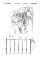
- FIG. 1 is a vertical cross-sectional view of a round baler constructed in accordance with the principles of the present invention, the near sidewall of the machine being removed to reveal internal details of construction;
- FIG. 2 is a fragmentary cross-sectional view similar to FIG. 1, but illustrating the manner in which a bale core is started in the machine;
- FIG. 3 is a fragmentary side elevational view of the lower left front portion of the baler illustrating components of the drive mechanism for rollers associated with the baling chamber;
- FIG. 4 is a horizontal cross-sectional view of the conveyor associated with the bale starter roller of the machine and taken substantially along line 4--4 of FIG. 3;
- FIG. 5 is a horizontal cross-sectional view similar to FIG. 4, but showing a second embodiment of a conveyor associated with the starter roller.
- the round baler 10 selected for illustration includes a wheeled chassis 12 having ground wheels 14 and a forwardly extending tongue 16 that is adapted for connection with a towing vehicle (not shown).
- the chassis 12 carries a pair of upright, laterally spaced sidewalls 17 and 19 which cooperate to define a space within which bale forming and bale wrapping operations may be carried out as the baler is advanced across a field.
- the variable chamber baler 10 includes a series of cooperating belts and rolls supported by the sidewalls 17, 19 for compacting and rolling the bale as it forms within the machine.
- the baler 10 is provided with a plurality of stationary rolls 18, 20, 22, 24, 26, 28, 30, and 32 which span the sidewalls 17, 19 in a general circular pattern viewing FIG. 1 for guiding a plurality of endless, side-by-side belts 36 as the belts 36 are driven linearly during bale formation and wrapping.
- a set of three movable slack takeup rolls 38, 39, and 40 are mounted near the upper portion of the baler on downwardly spring biased arm structure 42 to maintain tension on the belts 36, yet permit the paying out of stored slack as the bale increases in diameter during formation.
- the belts 36 are looped under the roll 18, over the takeup roll 38, and under the lower roll 32 to present a pair of opposed, front and rear runs 36a and 36b which are initially generally upright, as illustrated in phantom in FIG. 1 and in solid lines in FIG. 2, but which become bowed out in fore-and-aft directions, as illustrated in solid lines in FIG. 1, as the bale grows beyond its initial starting core dimensions.
- a pair of retaining rolls 44 and 46 are mounted on a second swingable arm structure 48 that is also spring-biased downwardly toward the phantom line position in FIG. 1, the retaining rolls 44, 46 receiving the belt runs 36a and 36b therebetween so as to form a baling chamber 50 between the runs 36a, 36b which is bounded at the sides by the sidewalls 17, 19.
- the chamber 50 assumes a generally upright, somewhat triangular configuration, as shown in phantom lines in FIG. 1 and solid lines in FIG. 2, with the retaining rollers 44, 46 at the apex of the chamber 50. Thereafter, the chamber 50 becomes distended and circular in transverse configuration as the growing bale pushes forwardly on the belt run 36a and rearwardly on the belt run 36b to cause additional slack to be paid out when the arm 48 rises as additional hay is progressively added to the bale.
- the chamber 50 is open at the bottom to present an infeed region 52 that is generally defined between the lower roll 32 and the upwardly and forwardly disposed roll 18.
- a pickup 54 supported generally below the infeed region 52 and forwardly adjacent the roll 32 is operable to lift crop material off the field as the baler 10 is advanced and to feed the material into the chamber 50 through the infeed region 52.
- additional infeed means in the form of ribbed rollers or other devices between pickup 54 and roll 32 could be provided to assist the pickup 54 in feeding materials into chamber 50.
- the roll 18 and the roll 22 are drive rolls for the belts 36 and are driven in clockwise directions viewing FIG. 1.
- the front run 36a is moving generally downwardly and forwardly while the rear run 36b is moving generally upwardly and slightly forwardly. Consequently, hay introduced into the chamber 50 via the infeed region 52 is acted upon by the upwardly moving rear run 36b and the downwardly moving front run 36a so as to tumble forwardly and coil into a core 56.
- Assisting in the formation of the core 56 is a transverse starter roller 58 in the infeed region 52 which forms part of a conveyor assembly 60 above the pickup 54 and below the roll 18.
- the starter roller 58 is in many respects similar to the bale positioning roller 134 shown in U.S. Pat. No. 4,182,101 assigned to the assignee of the present invention.
- the starter roller 134 of U.S. Pat. No. 4,182,101 is isolated and alone within the infeed region of the baler
- the starter roller 58 in the present invention has additional structure associated with it, i.e., the other components of the conveyor assembly 60, so as to keep the starter roller 58 from wrapping with crop material during operation.
- the starter roller 58 is positioned within the infeed region 52 approximately midway between the lower roll 32 and the upwardly and forwardly spaced roll 18. In this position, the starter roller 58 presents the inner or rear end of the conveyor assembly 60, while the opposite or front end of the conveyor assembly 60 is presented by a second transverse roller 62. Entraining the two rollers 58 and 62 is an endless web defined by three side-by-side, endless, flexible belts 64 as illustrated in FIG. 4, such belts 64 having an upper stretch 64a moving inwardly toward the infeed region 52 and a lower stretch 64b moving outwardly away from the infeed region 52, as illustrated in FIG. 2.
- each of the belts 64 has a plurality of transverse slats 66 thereon which are positioned at equally spaced intervals along the length of the belt 64.
- a pan 68 (FIGS. 1 and 2) which extends in a fore-and-aft direction substantially the entire distance between the starter roller 58 and the front roller 62 while spanning the entire transverse width of the baler 10 for the purpose of catching residue and other trash materials that might fall between the belts 64 of the conveyor 60.
- a plate-like shield 70 underneath the lower stretch 64b of the belts 64 extends the full transverse width of the baler and prevents infeeding hay on the pickup 54 from coming into contact with the outwardly moving lower belt stretch 64b.
- FIG. 3 illustrates the means by which drive roll 18, conveyor assembly 60, clean out discs 72 and starter roller 58 receive their driving power.
- input power to such mechanisms is provided by a jack shaft 74 situated at the rear of the tongue 16 which is connected through a drive line (not shown) to the power take off shaft of the towing vehicle.
- the jack shaft 74 carries a small sprocket 76 that is entrained by an endless, generally fore-and-aft extending chain 78.
- the chain 78 also wraps around a sprocket 80 on a shaft 82 of the clean out discs 72 and further entrains a large sprocket (not shown) carried by a stub shaft 84 of the drive roll 18.
- a second large sprocket (also not shown) on the stub shaft 84 is entrained by a second drive chain 86 that extends rearwardly from the stub shaft 84 to entrain a sprocket 88 on the outer end of a shaft 90 associated with the starter roller 58.
- a third large sprocket 92 which is entrained by a generally vertically extending endless drive chain 94 leading upwardly to the upper roll 22 for supplying driving power to the latter.
- FIG. 5 shows a second embodiment of the conveyor assembly, such second embodiment being noted by the numeral 160.
- the conveyor 160 is identical in all respects to the conveyor 60, except that the belts 164 of conveyor 160 do not have cross slats, as in the first embodiment, and the belts 164 are narrower and more numerous than the belts 64.
- the starter roller 158 of the conveyor assembly 160 is identical to the starter roller 58 of the first embodiment.
- the incoming crop materials are engaged by the upwardly moving belt stretch 36b and the downwardly moving front belt stretch 36a and are caused to coil and tumble within the baling chamber 50.
- the core 56 which results from this action tends to rest upon the inner end of the conveyor assembly 60, and because the starter roller 58 is rotating in a clockwise direction, the inner end of the conveyor 60 helps impart a coiling action to the core 56 at this time.
- the advantages of having a rotary core starter are retained in the present invention.
- the incoming crop materials flow more directly rearwardly into a nip formed at the bottom of the bale with the underlying bottom roll 32.
- a representation of a full size bale is denoted by cross hatching in FIG. 1 and is designated by the numeral 96. It will be seen that the incoming hay is thus no longer presented up into the area above the starter roller 58 where it has a tendency to attempt to wrap on the roller 58 during the early stages of bale formation.
- the conveyor 60 is of less importance in the latter stages of bale growth than in the initial core starting stage thereof.
- bale 96 may be tightly wrapped with either twine or a web-type wrapping material, such as a net material currently available from Exxon Chemical Company under the trade designation "Bale Lok” net wrap.
- a swingable twine dispensing tube 98 is also provided adjacent the front of the baler and projecting rearwardly into the space between the conveyor assembly 60 and the drive roll 18 for dispensing a supply of twine to the bale 96 in the event twine is desired as a wrapping material instead of the net wrap.
- the baler 10 may be provided with a suitable net wrap attachment (not shown).
- One such suitable net wrap attachment is disclosed in co-pending application Ser. No. 07/772,238, filed Oct.
- the rear section of the machine along a parting line 100 may be swung upwardly and rearwardly to open the bale chamber and discharge the finished bale.
- Ratzlaff et al., entitled “Round Baler Having Anti-Wrapping Idler Rolls”, relates to a round baler provided with idler rolls that cause slight speed differential between different belts on the same idler roll so as to provide a self-cleaning action.
- the inventions of these two above-identified applications form no part of the invention claimed in the present application and are identified solely for purposes of providing full disclosure of generally related subject matters.
Landscapes
- Life Sciences & Earth Sciences (AREA)
- Environmental Sciences (AREA)
- Storage Of Harvested Produce (AREA)
- Organic Low-Molecular-Weight Compounds And Preparation Thereof (AREA)
Priority Applications (4)
| Application Number | Priority Date | Filing Date | Title |
|---|---|---|---|
| US07/811,073 US5228280A (en) | 1991-12-20 | 1991-12-20 | Round baler having anti-wrapping core starter |
| AU25080/92A AU669485B2 (en) | 1991-12-20 | 1992-08-20 | Round baler having anti-wrapping core starter |
| PCT/US1992/006986 WO1993012643A1 (fr) | 1991-12-20 | 1992-08-20 | Presse a ballots ronds equipee d'un demarreur du c×ur du ballot anti-enroulement |
| EP92918974A EP0619700A4 (fr) | 1991-12-20 | 1992-08-20 | Presse a ballots ronds equipee d'un demarreur du c ur du ballot anti-enroulement. |
Applications Claiming Priority (1)
| Application Number | Priority Date | Filing Date | Title |
|---|---|---|---|
| US07/811,073 US5228280A (en) | 1991-12-20 | 1991-12-20 | Round baler having anti-wrapping core starter |
Publications (1)
| Publication Number | Publication Date |
|---|---|
| US5228280A true US5228280A (en) | 1993-07-20 |
Family
ID=25205475
Family Applications (1)
| Application Number | Title | Priority Date | Filing Date |
|---|---|---|---|
| US07/811,073 Expired - Fee Related US5228280A (en) | 1991-12-20 | 1991-12-20 | Round baler having anti-wrapping core starter |
Country Status (4)
| Country | Link |
|---|---|
| US (1) | US5228280A (fr) |
| EP (1) | EP0619700A4 (fr) |
| AU (1) | AU669485B2 (fr) |
| WO (1) | WO1993012643A1 (fr) |
Cited By (10)
| Publication number | Priority date | Publication date | Assignee | Title |
|---|---|---|---|---|
| US5417043A (en) * | 1994-09-08 | 1995-05-23 | Vermeer Manufacturing Company | Notched belts for a baler of large cylindrical bales |
| US5791854A (en) * | 1996-09-10 | 1998-08-11 | Cattaruzzi; Bruno | Rotating trailer for handling poultry cages |
| US6477824B2 (en) | 2001-01-24 | 2002-11-12 | Agco Corporation | Round baler having incoming crop deflectors |
| US20030029383A1 (en) * | 2001-08-13 | 2003-02-13 | Ward Nicholas A. | Dynamic control of wafer processing paths in semiconductor manufacturing processes |
| US20050198935A1 (en) * | 2004-03-12 | 2005-09-15 | Duratech Industries International, Inc. | Round baler leaf reclamation device |
| US20050198934A1 (en) * | 2004-03-12 | 2005-09-15 | Duratech Industries International, Inc. | Round baler reclamation belt |
| US20150307303A1 (en) * | 2012-11-28 | 2015-10-29 | Knauf Inuslation Gmbh | Packaging machine with variable-width belt system |
| CN114557199A (zh) * | 2022-03-09 | 2022-05-31 | 河南农业大学 | 圆捆机轴向变腔式卷捆机构 |
| US11419271B2 (en) * | 2020-01-13 | 2022-08-23 | Cnh Industrial America Llc | Agricultural baler with independent tensioning arms |
| EP4074162A1 (fr) * | 2021-04-16 | 2022-10-19 | Maschinenfabrik Bernard Krone GmbH & Co. KG | Presse à balles rondes pourvue de rouleau de démarrage et d'élément de déviation pouvant être dévié élastiquement |
Families Citing this family (4)
| Publication number | Priority date | Publication date | Assignee | Title |
|---|---|---|---|---|
| DE10243295B4 (de) * | 2002-09-18 | 2010-11-11 | Welger Maschinenfabrik Gmbh | Rundballenpresse |
| MX353590B (es) | 2012-11-14 | 2018-01-19 | Royal Duyvis Wiener Bv | Aparato para secar y/o tostar granos o virutas. |
| DE102014006179A1 (de) * | 2014-04-29 | 2015-10-29 | Alois Pöttinger Maschinenfabrik Gmbh | Erntemaschine |
| GB201820057D0 (en) | 2018-12-10 | 2019-01-23 | Agco Wolfenbuettel Gmbh | Improved bale wrapping apparatus |
Citations (4)
| Publication number | Priority date | Publication date | Assignee | Title |
|---|---|---|---|---|
| US3722197A (en) * | 1972-01-03 | 1973-03-27 | G Vermeer | Method and machine for forming a large round bale of a fibrous material |
| US4182101A (en) * | 1977-12-01 | 1980-01-08 | Hesston Corporation | Machine for coiling fibrous crop materials into large round bales |
| US4633659A (en) * | 1984-01-27 | 1987-01-06 | Deere & Company | Cylindrical bale-forming press |
| US4782652A (en) * | 1987-09-29 | 1988-11-08 | Hay And Forage Corporation | Round baler having anti-plugging means |
Family Cites Families (3)
| Publication number | Priority date | Publication date | Assignee | Title |
|---|---|---|---|---|
| DE3468616D1 (en) * | 1984-01-27 | 1988-02-18 | Deere John | Rotobaler with driven bale starter roll |
| GB2228227A (en) * | 1989-01-30 | 1990-08-22 | Deere & Co | Machine for forming cylindrical bales of crop |
| FR2666957B1 (fr) * | 1990-09-24 | 1994-04-15 | Institut Tech Agricole Lin | Procede de conditionnement pour des matieres fibreuses souples notamment du lin teille, et dispositif de mise en óoeuvre. |
-
1991
- 1991-12-20 US US07/811,073 patent/US5228280A/en not_active Expired - Fee Related
-
1992
- 1992-08-20 EP EP92918974A patent/EP0619700A4/fr not_active Ceased
- 1992-08-20 WO PCT/US1992/006986 patent/WO1993012643A1/fr not_active Ceased
- 1992-08-20 AU AU25080/92A patent/AU669485B2/en not_active Ceased
Patent Citations (4)
| Publication number | Priority date | Publication date | Assignee | Title |
|---|---|---|---|---|
| US3722197A (en) * | 1972-01-03 | 1973-03-27 | G Vermeer | Method and machine for forming a large round bale of a fibrous material |
| US4182101A (en) * | 1977-12-01 | 1980-01-08 | Hesston Corporation | Machine for coiling fibrous crop materials into large round bales |
| US4633659A (en) * | 1984-01-27 | 1987-01-06 | Deere & Company | Cylindrical bale-forming press |
| US4782652A (en) * | 1987-09-29 | 1988-11-08 | Hay And Forage Corporation | Round baler having anti-plugging means |
Cited By (14)
| Publication number | Priority date | Publication date | Assignee | Title |
|---|---|---|---|---|
| US5417043A (en) * | 1994-09-08 | 1995-05-23 | Vermeer Manufacturing Company | Notched belts for a baler of large cylindrical bales |
| US5791854A (en) * | 1996-09-10 | 1998-08-11 | Cattaruzzi; Bruno | Rotating trailer for handling poultry cages |
| US6477824B2 (en) | 2001-01-24 | 2002-11-12 | Agco Corporation | Round baler having incoming crop deflectors |
| US20030029383A1 (en) * | 2001-08-13 | 2003-02-13 | Ward Nicholas A. | Dynamic control of wafer processing paths in semiconductor manufacturing processes |
| US7337603B2 (en) | 2004-03-12 | 2008-03-04 | Duratech Industries International, Inc. | Round baler leaf reclamation device |
| US20050198934A1 (en) * | 2004-03-12 | 2005-09-15 | Duratech Industries International, Inc. | Round baler reclamation belt |
| US20050198935A1 (en) * | 2004-03-12 | 2005-09-15 | Duratech Industries International, Inc. | Round baler leaf reclamation device |
| US20150307303A1 (en) * | 2012-11-28 | 2015-10-29 | Knauf Inuslation Gmbh | Packaging machine with variable-width belt system |
| US9434566B2 (en) * | 2012-11-28 | 2016-09-06 | Knauf Insulation, Inc. | Packaging machine with variable-width belt system |
| US11419271B2 (en) * | 2020-01-13 | 2022-08-23 | Cnh Industrial America Llc | Agricultural baler with independent tensioning arms |
| EP4074162A1 (fr) * | 2021-04-16 | 2022-10-19 | Maschinenfabrik Bernard Krone GmbH & Co. KG | Presse à balles rondes pourvue de rouleau de démarrage et d'élément de déviation pouvant être dévié élastiquement |
| US12342762B2 (en) | 2021-04-16 | 2025-07-01 | Maschinenfabrik Bernard Krone GmbH & Co. KG | Round baler with starter roll and elastically deflectable deflector element |
| CN114557199A (zh) * | 2022-03-09 | 2022-05-31 | 河南农业大学 | 圆捆机轴向变腔式卷捆机构 |
| CN114557199B (zh) * | 2022-03-09 | 2023-10-24 | 河南农业大学 | 圆捆机轴向变腔式卷捆机构 |
Also Published As
| Publication number | Publication date |
|---|---|
| AU669485B2 (en) | 1996-06-13 |
| AU2508092A (en) | 1993-07-28 |
| EP0619700A4 (fr) | 1995-01-11 |
| WO1993012643A1 (fr) | 1993-07-08 |
| EP0619700A1 (fr) | 1994-10-19 |
Similar Documents
| Publication | Publication Date | Title |
|---|---|---|
| US5228280A (en) | Round baler having anti-wrapping core starter | |
| US4428282A (en) | Cylindrical baler with self-cleaning drive roller | |
| EP0252457B1 (fr) | Machine pour former des balles cylindriques de matières récoltées | |
| US6050052A (en) | Round baler having positive start wrapper dispensing mechanism | |
| US5595055A (en) | Pickup apparatus for a round baler | |
| US4078733A (en) | Apparatus for separating and distributing rolled bales of agricultural material | |
| US6029434A (en) | Down turning stub augers on wide pick-up for round balers | |
| CA1309293C (fr) | Instrument de mise en balles cylindriques muni d'un mecanisme anti-obturation | |
| US5729953A (en) | Round bale wrapper dispensing apparatus | |
| US9415888B2 (en) | Net wrapping system back wrap roll | |
| US4597254A (en) | Continuous roll baler | |
| US5479767A (en) | Trash baffle for round baler | |
| US5097760A (en) | Powered trash removal apparatus for round baler | |
| US5165333A (en) | Round baler having anti-wrapping idler rolls | |
| US9402347B2 (en) | Baler rear shield mechanism | |
| US4444098A (en) | Cylindrical baler with self-cleaning gate | |
| US5819515A (en) | Eased inlet tailgate roll arrangement for variable chamber round baler | |
| US20050091959A1 (en) | Baler | |
| US4319446A (en) | Infeed means for round baler | |
| US5193450A (en) | Residue reducing belt roller construction for round balers | |
| EP0235787B1 (fr) | Machine pour former des balles cylindriques | |
| US5299684A (en) | Hay baler | |
| EP0316506B1 (fr) | Machine pour former des balles rondes | |
| US5749289A (en) | Tall sleeves for round baler drive rolls | |
| US20010047640A1 (en) | Method and apparatus for forming and wrapping round bales |
Legal Events
| Date | Code | Title | Description |
|---|---|---|---|
| AS | Assignment |
Owner name: HAY & FORAGE INDUSTRIES, KANSAS Free format text: ASSIGNMENT OF ASSIGNORS INTEREST.;ASSIGNORS:RATZLAFF, HOWARD J.;FELL, FEROL S.;REEL/FRAME:005956/0799 Effective date: 19911219 |
|
| FPAY | Fee payment |
Year of fee payment: 4 |
|
| REMI | Maintenance fee reminder mailed | ||
| AS | Assignment |
Owner name: COOPERATIEVE CENTRALE RAIFFEISEN-BOERENLEENBANK, B Free format text: SECURITY AGREEMENT;ASSIGNOR:HAY & FORAGE INDUSTRIES;REEL/FRAME:011742/0152 Effective date: 20010417 |
|
| LAPS | Lapse for failure to pay maintenance fees | ||
| FP | Lapsed due to failure to pay maintenance fee |
Effective date: 20010720 |
|
| STCH | Information on status: patent discontinuation |
Free format text: PATENT EXPIRED DUE TO NONPAYMENT OF MAINTENANCE FEES UNDER 37 CFR 1.362 |