US5233644A - Cordless telephone with actuation of off-hook condition by operation of dial key - Google Patents
Cordless telephone with actuation of off-hook condition by operation of dial key Download PDFInfo
- Publication number
- US5233644A US5233644A US07/637,117 US63711791A US5233644A US 5233644 A US5233644 A US 5233644A US 63711791 A US63711791 A US 63711791A US 5233644 A US5233644 A US 5233644A
- Authority
- US
- United States
- Prior art keywords
- handset unit
- base unit
- unit
- handset
- command signal
- Prior art date
- Legal status (The legal status is an assumption and is not a legal conclusion. Google has not performed a legal analysis and makes no representation as to the accuracy of the status listed.)
- Expired - Fee Related
Links
Images


Classifications
-
- H—ELECTRICITY
- H04—ELECTRIC COMMUNICATION TECHNIQUE
- H04M—TELEPHONIC COMMUNICATION
- H04M1/00—Substation equipment, e.g. for use by subscribers
- H04M1/72—Mobile telephones; Cordless telephones, i.e. devices for establishing wireless links to base stations without route selection
- H04M1/725—Cordless telephones
- H04M1/72502—Cordless telephones with one base station connected to a single line
- H04M1/72505—Radio link set-up procedures
-
- H—ELECTRICITY
- H04—ELECTRIC COMMUNICATION TECHNIQUE
- H04M—TELEPHONIC COMMUNICATION
- H04M1/00—Substation equipment, e.g. for use by subscribers
- H04M1/72—Mobile telephones; Cordless telephones, i.e. devices for establishing wireless links to base stations without route selection
- H04M1/725—Cordless telephones
- H04M1/73—Battery saving arrangements
Definitions
- the present invention generally relates to cordless telephones and, more particularly, to a cordless telephone in which a battery incorporated therein can be prevented from being consumed uselessly and in which a telephone line network can be prevented from being captured meaninglessly.
- the user can dial a number for making an outgoing call or can receive an incoming call by only picking up a transmitter and receiver from the telephone body.
- a proposed cordless telephone has a special function which might be called a "quick talk" function. This type of cordless telephone having such quick talk function will be explained hereinafter.
- the handset unit of the cordless telephone system generally incorporates therein a rechargeable battery as an operation power source so that the base unit has a charging circuit therein or a special charging stand is provided for charging the battery of the handset unit.
- the handset unit When the handset unit is not in use, the handset unit is set in the base unit at its predetermined charging position or the handset unit is placed in the charging stand. Then, in this condition, a charging current flows to the battery incorporated within the handset unit so that the handset unit is placed in the standby mode on the basis of a detected output of the charging current, and so that the base unit also is placed in the standby mode.
- the user When the user wants to make an outgoing call or the user wants to receive an incoming call, the user picks up the handset unit from the base unit or from the charging stand. Then, the charging current is inhibited from flowing to the handset unit and a process corresponding to "depress a talk button" in the above-mentioned item (2) is performed in the handset unit on the basis of the detected output, so that a communication channel is opened between the handset unit and the base unit and the base unit is connected to the telephone line network.
- the cordless telephone system has such quick talk function, the cordless telephone can be utilized as the standard telephone set while the advantages of the cordless telephone are still maintained.
- the communication channel is unavoidably opened between the handset unit and the base unit and also the base unit is unavoidably connected to the telephone line network, so that the battery of the handset unit is consumed uselessly.
- the telephone line network is occupied meaninglessly (the telephone line network is captured uselessly), which causes trouble in the telephone office and which hinders the cordless telephone from receiving an incoming call.
- a cordless telephone having a base unit connected to a telephone line network and a handset unit connected to the base unit through a communication channel upon telephone conversation is comprised of a detecting circuit provided in the handset unit for detecting that the handset unit is picked up from a predetermined standby place position, and a circuit for inhibiting the base unit from making a connection request to the telephone line network on the basis of a detection output from the detecting circuit, wherein when the detection output of the detecting circuit indicates that the handset unit is picked up from the predetermined standby place position and when a dial key of the handset unit is operated, the base unit is connected to the telephone line network.
- a cordless telephone having a base unit connected to a telephone line network and a handset unit connected to the base unit through a communication channel upon telephone conversation is comprised of a detecting circuit provided in the handset unit for detecting that the handset unit is picked up from a predetermined standby place position, and a circuit for inhibiting the base unit from making a connection request to the telephone line network on the basis of a detection output from the detecting circuit, wherein when the detection output of the detecting circuit indicates that the handset unit is picked up from the predetermined standby place position and when a dial key of the handset unit is operated, the communication channel is opened between the handset unit and the base unit.
- a cordless telephone having a base unit connected to a telephone line network and a handset unit connected to the base unit through a communication channel upon telephone conversation is comprised of a detecting circuit provided in the handset unit for detecting that the handset unit is picked up from a predetermined standby place position, and a circuit for inhibiting the base unit from making a connection request to the telephone line network on the basis of a detection output from the detecting circuit, wherein when the detection output of the detecting circuit indicates that the handset unit is picked up from the predetermined standby place position, the communication channel is opened between the handset unit and the base unit and when a dial key of the handset unit is operated, the base unit is connected to the telephone line network and dial data of the dial key is transmitted to the telephone line network from the handset unit through the base unit to thereby make an outgoing call.
- FIG. 1 is a schematic block diagram showing an overall circuit arrangement of an embodiment of a cordless telephone system according to the present invention
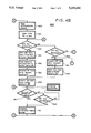
- FIG. 2 (formed of FIGS. 2A, 2B and 2C provided on three sheets of drawings so as to permit the use of a suitably large scale) is a flowchart to which reference is made in explaining an operation of the cordless telephone system of the present invention
- FIG. 3 is a diagram of a signal format to which reference is made in explaining the operation of the present invention.
- FIG. 4 (formed of FIGS. 4A, 4B and 4C provided on three sheets of drawings so as to permit the use of a suitably large scale) is a flowchart to which reference is made in explaining the present invention.
- FIG. 1 shows an overall arrangement of an embodiment of the cordless telephone system according to the present invention, wherein reference numeral 1 designates a handset unit, 2 a base unit, 3 a telephone line network (external line) and 50 a charging stand.
- reference numeral 1 designates a handset unit, 2 a base unit, 3 a telephone line network (external line) and 50 a charging stand.
- a transmitting circuit 110 is adapted to convert an audio signal St and a command signal CMND (which will be more fully referred to later) into an FM (frequency-modulated) up channel signal Su and transmit the same.
- a receiving circuit 120 is adapted to receive and demodulate an FM down channel signal Sd to provide an audio signal Sr and the command signal CMND.
- the receiving circuit 120 also detects limiter noise generated, for example, by an intermediate frequency amplifier to thereby derive a detection signal SQLC which indicates the presence or absence of the down channel signal Sd.
- the handset unit 1 is provided with a dial key 131 and a talk key 132.
- the talk key 132 is of a non-lock type push switch so that, each time the talk key 132 is pressed, the handset unit 1 is alternately changed between the standby mode and the talk mode.
- the handset unit 1 In the standby mode, the handset unit 1 is in the standby mode for making an outgoing call therefrom and receives and monitors the down channel to await a connection request from the base unit 2.
- the talk mode the handset unit 1 performs continuous reception and transmission between it and the base unit 2.
- the handset unit 1 is further provided with function keys 133 to 137 such as a hold key and so on. These function keys 133 to 137 are of non-lock type push switches and the keys 134, 135 and 136 are not shown for simplicity. Further, the handset unit 1 emanates provided with a speaker 139 from which a ringer sound is and a microcomputer 140 which is adapted to control the entire system of this handset unit 1.
- the microcomputer 140 is adapted to generate the command signal CMND that is transmitted via the transmitting circuit 110, and to identify the command signal CMND and the detection signal SQLC sent from the receiving circuit 120. Further, the microcomputer 140 generates control signals TCTL and RCTL by which the transmission and reception of the transmitting circuit 110 and the receiving circuit 120 are permitted and inhibited and the channel is designated. Furthermore, the microcomputer 140 stores therein a routine 300 shown in the flowchart of FIG. 2. In this case, FIG. 2 is formed of FIGS. 2A, 2B and 2C provided on three sheets of drawings so as to permit a suitably large scale thereof.
- a memory 141 which might be a read only memory (ROM), and this ROM 141 stores therein a 25-bit system identifying code SYID used to distinguish this cordless telephone from other cordless telephones.
- ROM read only memory
- a battery 151 is provided as a power source and is a rechargeable battery such as a nickel-cadmium battery. An output voltage of this battery 151 is supplied to respective portions of the handset unit 1 as operation voltages.
- Reference numeral 152 designates a charging voltage input contact and 153 a charging detecting circuit.
- a charging circuit 51 In the charging stand 50, there is provided a charging circuit 51, and this charging circuit 51 converts a commercially available AC voltage into a predetermined DC voltage, this DC voltage being fed to a charging voltage output contact 52.
- the contacts 52 and 152 are brought in contact with each other, whereby the output voltage of the charging circuit 51 is supplied to the battery 151, so that the battery 151 is charged.
- the contacts 52 and 152 are disconnected to inhibit the battery 151 from being charged.
- the detecting circuit 153 detects whether or not the battery 151 is charged. In other words, a detection output Sc from the detecting circuit 153 is used to detect whether or not the handset unit 1 is placed in the charging stand 50.
- the base unit 2 includes a transmitting circuit 210 and a receiving circuit 220 which are similar to the transmitting circuit 110 and the receiving circuit 120 in the handset unit 1.
- the base unit 2 In the standby mode, the base unit 2 awaits the arrival of an incoming call from the telephone line network 3, and the receiving circuit 220 awaits a connection request from the handset unit 1 by receiving and monitoring the up channel signal.
- the base unit 2 In the talk mode, the base unit 2 performs continuous reception and transmission between it and the handset unit 1.
- a microcomputer 240 that is used to control the entirety of this cordless telephone system. That is, this microcomputer 240 performs processing similar to that of the microcomputer 140 and also controls the operation of the entirety of this cordless telephone system.
- a ROM 241 corresponds with the ROM 141 of the handset unit 1 and in stores the system identifying code SYID.
- reference numeral 261 designates a four-to-two line converting circuit, 262 a switch circuit which corresponds with the hook switch of the standard telephone set, 263 a dial tone signal (i.e. DTMF signal) generating circuit and 264 a ring tone signal detecting circuit.
- a dial tone signal i.e. DTMF signal
- the base unit 2 is not provided with the charging circuit for the battery 152 of the handset unit 1.
- FIG. 3 shows an example of a signal format of the command signal CMND.
- This command signal CMND includes a bit synchronizing (sync.) signal BSYN of 24 bits at the head thereof and a frame sync. signal FSYN thereafter.
- these signals BSYN and FSYN have particular bit patterns expressed as
- the command signal CMND includes a system identifying code SYID of 25 bits succeeding the signal FSYN, an error correcting code ECC of 12 bits for the system identifying code SYID, a dummy bit DBIT of 3 bits and a control code CTRL of 5 bytes, in that order.
- a first byte CTL1 is assigned to the code that indicates the control contents of the handset unit 1 and the base unit 2 and second to fifth bytes CTL2 to CTL5 are parameters and data that are associated with the first byte CTL1.
- the handset unit 1 or the base unit 2 When the handset unit 1 or the base unit 2 receives the command signal CMND, it is determined by the microcomputer 140 or 240 whether or not the identifying code SYID involved in that command signal CMND is identical with the identifying code SYID stored in the ROM 141 or 241 thereof. Only when the identifying codes SYID are identical, the command signal CMND is made effective, while when the identifying codes SYID are not coincident with each other, the command signal CMND is made ineffective.
- the handset unit 1 In the standby mode of the quick talk mode, the handset unit 1 is placed in the charging stand 50 and the battery 151 is charged by the output voltage of the charging circuit 51. At that time, steps 301 to 303 of the routine 300 are repeatedly executed by the microcomputer 140.
- step 301 by observing the detection output Sc of the detecting circuit 153, it is determined at step 301 whether or not the handset unit 1 is placed in the stand 50. In that case, since the handset unit 1 is placed in the stand 50, then processing proceeds from step 301 to the next decision step 302. It is determined in decision step 302 by observing the detection signal SQLC whether or not the FM signal Sd from the base unit 2 is received by the handset unit 1. If the FM signal Sd is not received by the handset unit 1 as represented by a NO at step 302, then processing returns from step 302 to step 301.
- step 302 If on the other hand the FM signal Sd is received by the handset unit 1 as represented by a YES at step 302, then processing proceeds from step 302 to the next decision step 303.
- decision step 303 the FM signal Sd is demodulated to provide the command signal CMND, and it is determined whether or not the system identifying code SYID involved in this command signal CMND is identical with the system identifying code SYID stored in the ROM 141 and also it is determined whether or not this command signal CMND is identical with the command signal CMND whose control code CTRL indicates a request of an incoming call.
- control code CTRL of this command signal CMND does not indicate an incoming call request as represented by a NO at step 303, then the processing returns from step 303 to step 301. Accordingly, when the handset unit 1 is placed in the stand 50, this state of the handset unit 1 and the occurrence of an incoming call request are monitored.
- step 301 When the user picks up the handset unit 1 from the stand 50, this is detected at step 301 on the basis of the detecting signal Sc and processing proceeds from step 301 to step 321 (see FIG. 2B).
- step 321 a timer TM implemented by software is cleared to [0] and then the loop formed of steps 322, 323, 324, 325, 326 and 327 is repeatedly executed.
- step 322 it is determined in decision step 322 whether or not the dial key 131 is depressed. If the dial key 131 is not pressed as represented by a NO at step 322, then processing proceeds from step 322 to the next decision step 323. It is determined in decision step 323 whether or not the talk key 132 is depressed. If the talk key 132 is not pressed as represented by a NO at step 323, then processing proceeds from step 323 to the next decision step 324.
- decision step 324 and the next decision step 325 similarly to steps 302 and 303, it is determined whether or not the request of the incoming call from the base unit 2 is received by the handset unit 1. If not, the processing proceeds from step 324 or 325 to the next decision step 326. It is determined in decision step 326 whether or not a predetermined time limit of the timer TM, for example, 20 seconds, has passed. If 20 seconds has not yet passed as represented by a NO at step 326, then processing proceeds from step 326 to step 327, whereat time limit of the timer TM is incremented by a predetermined time. Then, processing returns from step 327 to step 322.
- a predetermined time limit of the timer TM for example, 20 seconds
- the loop of steps 322 to 327 is repeated until the time limit of the timer TM, for example, 20 seconds, has passed.
- step 322 If the user presses the numeral key of the dial key 132 to input the first digit of the phone number to be called during the loop of steps 322 to 327, then this depression of the numeral key is detected in step 322, and processing proceeds from step 322 to step 331.
- step 331 data of the first digit of the phone number is stored in a buffer memory BF (not shown) of the microcomputer 140. Further, if the user depresses the numeral key of the dial key 131 to input the second digit and the following digits of the phone number to be called, then data of the numerals of the phone number to be called are sequentially stored in the buffer memory BF of the microcomputer 140 in step 332.
- step 332 If the user inputs all data of the phone number to be called (e.g., if the input of the dial key 131 is interrupted for three seconds), then processing proceeds from step 332 to step 333.
- step 333 transmission by the transmitting circuit 110 is permitted and a command signal CMND whose control code CTRL indicates an outgoing call request is generated and supplied to the transmitting circuit 110, in which it is converted into the FM up channel signal Su.
- This FM signal Su is transmitted through an antenna 100 to the base unit 2.
- the signal (radio wave) Su is received at an antenna 200 and the FM signal Su is demodulated by the receiving circuit 220 to provide the command signal CMND.
- This command signal CMND is supplied to the microcomputer 240 which then determines whether or not the system identifying signal SYID involved in that command signal CMND is identical with the system identifying code SYID stored in the ROM 241.
- the microcomputer 240 permits the transmitting circuit 210 to transmit the down channel signal which is paired with the channel through which the FM signal Su is received. Thereafter, a predetermined command signal CMND is accessed between the base unit 2 and the handset unit 1 to thereby open a communication channel between the base unit 2 and the handset unit 1.
- the switch circuit 262 is placed in the off-hook state to connect the transmitting circuit 210 and the receiving circuit 220 to the telephone line network 3 through the converting circuit 261 and the switch circuit 262.
- step 333 the handset unit 1 and the base unit 2 are connected to each other via the channels of the FM signals Su and Sd and the base unit 2 is connected to the telephone line network 3.
- the handset unit 1 is connected via the base unit 2 to the telephone line network 3.
- step 334 data of the phone number to be called stored in the buffer memory BF are sequentially read out, and a command signal CMND whose control code CTRL indicates the transmission of the phone number and the phone number of the other party is generated, this command signal CMND being transmitted to the base unit 2.
- the command signal CMND is generated by the receiving circuit 220 and the control code CTRL of this command signal CMND indicates the transmission of the telephone number and the phone number to be called so that the microcomputer 240 controls the generating circuit 263 in accordance with the phone number to generate a dial tone signal corresponding to the phone number transmitted from the handset unit 1.
- This dial tone signal is transmitted through the converting circuit 261 and the switch circuit 262 to the telephone line network 3.
- the user can make an outgoing call by picking up the handset unit 1 from the stand 50 and by depressing the dial key 131 to input the phone number to be called, or the user can make an outgoing call by the cordless telephone similarly to the standard telephone set.
- the audio signal Sr from the other party is supplied to the transmitting circuit 210 via the signal line formed of the telephone line network 3, the switch circuit 262 and the converting circuit 261, in which this signal Sr is converted into the FM down channel signal Sd, this signal Sd being transmitted from the antenna 200.
- This signal Sd is received by the handset unit 1 and the receiving circuit 120 derives the audio signal Sr, this audio signal Sr being fed to the telephone receiver 121.
- the audio signal St from the telephone transmitter 111 is supplied to the transmitting circuit 110, in which it is converted into the up channel FM signal Su, this signal Su being transmitted to the base unit 2 from the antenna 100.
- the transmitted signal Su is received by the base unit 2 and the receiving circuit 220 derives the signal St.
- This signal St is transmitted through the converting circuit 261 and the switch circuit 262 to the telephone line network 3, thereby being transmitted to the phone of the other party. Therefore, the communication channel is opened between the handset unit 1 and the base unit 2, thus making it possible for the user to carry out make a telephone conversation between the called party and the handset unit 1 from now on.
- steps 351 and 352 are repeated.
- processing by the microcomputer 140 proceeds from step 334 to the next decision step 351, whereat it is determined by observing the detection signal Sc whether or not the handset unit 1 is placed in the stand 50. If the handset unit 1 is not placed in the stand 50 as represented by a NO at step 351, or during the telephone conversation, then processing proceeds from step 351 to the next decision step 352. In step 352, it is determined whether or not the talk key 132 is depressed. If the talk key 132 is not depressed as represented by a NO at step 352, then processing returns from step 352 to step 351. Therefore, during the telephone conversation, it is determined by the monitoring process whether or not the handset unit 1 is placed in the stand 50 or it is also determined by the monitoring process whether or not the talk key 132 is depressed.
- step 351 When the telephone conversation is finished and the user places the handset unit 1 in the stand 50, this status of the handset unit 1 on the stand 50 is detected at step 351, and processing proceeds from step 351 to step 361.
- step 361 a command signal CMND whose control code CTRL indicates the end of the telephone conversation is generated, and this command signal CMND is transmitted to the base unit 2.
- the transmitting circuit 120 is inhibited from transmitting the signal, or the telephone conversation finalizing process is executed and then the processing returns from step 361 to step 301. Therefore, when the user places the handset unit 1 in the stand 50 after the telephone conversation is finished, the handset unit 1 is set in the standby mode.
- the command signal CMND whose control code CTRL indicates the finalizing process of telephone conversation is transmitted thereto from the handset unit 1, whereby the transmitting circuit 210 is inhibited from transmitting the signal and the switch circuit 262 is placed in the on-hook state and so on. That is, the conversation finalizing process is performed, and then the base unit 2 is set in the standby mode.
- the handset unit 1 and the base unit 2 are set in the standby mode.
- the user can finish the telephone conversation by placing only the handset unit 1 in the stand 50 similarly to the standard telephone set.
- step 303 it is determined whether or not the system identifying codes SYID are coincident with each other. In that case, since the system identifying codes SYID are coincident with each other and the control code CTRL in the command signal CMND indicates an incoming call request, this request is detected at decision step 303, and then processing proceeds from step 303 to step 304.
- step 304 the transmitting circuit 110 is permitted to transmit the up channel signal which is paired with the down channel through which the FM signal Su is received, whereby a predetermined command signal CMND is accessed between the base unit 2 and the handset unit 1 to open the communication channel between the base unit 2 and the handset unit 1 from now on.
- step 305 the microcomputer 140 controls the oscillation circuit 138 to generate a ring signal, and this ring signal is supplied to the speaker 139 which emits a ringing sound to announce the arrival of the incoming call.
- processing proceeds from step 305 to the next decision step 306, and steps 306 and 307 are repeated until the user picks up the handset unit 1 from the stand 50.
- step 306 by studying the detection signal Sc in step 306, it is determined whether or not the handset unit 1 is picked up from the stand 50. If the handset unit 1 is not picked up from the stand 50 as represented by a NO at step 306, then processing proceeds from step 306 to the next decision step 307. It is determined in step 307 whether or not a command signal CMND whose control code CTRL indicates a cancellation of the incoming call is transmitted from the base unit 2. If the command signal CMND is not transmitted from the base unit 2 as represented by a NO at step 307, then processing returns from step 307 to step 306.
- step 306 When a ringing sound is emitted to announce the arrival of the incoming call and the user picks up the handset unit 1 from the stand 50, this is detected at step 306 on the basis of the detection signal Sc, and then processing proceeds from step 306 to 308.
- step 308 the oscillation circuit 138 is inhibited from generating the ring signal and the speaker 139 stops emitting the ringing sound.
- step 309 a command signal CMND whose control code CTRL indicates a request for the off-hook state is generated and this command signal CMND is transmitted to the base unit 2 via the up communication channel.
- the switch circuit 262 is placed in the off-hook state in accordance with the transmitted command signal CMND.
- the telephone line network 3 is connected to the transmitter 111 and the receiver 121 through the base unit 2 and the handset unit 1, thus making it possible for the user to carry out a telephone conversation with the other party.
- the user can receive an incoming call by picking up the handset unit 1 from the stand 50, or the user can receive an incoming call in a manner similar to a standard telephone set.
- step 309 the processing of the microcomputer 140 proceeds from step 309 to step 351 and the steps 351 and 352 are repeated as described above.
- the ring tone signal supplied from the telephone line network 3 to announce the arrival of the incoming call is not detected by the detecting circuit 264 any more, whereby a command signal CMND whose control code CTRL indicates cancellation of the incoming call is generated in the base unit 2 and this command signal CMND is transmitted to the handset unit 1.
- step 307 this command signal CMND is detected in decision step 307, and processing proceeds from step 307 to step 310, whereat the oscillation circuit 138 is inhibited from generating a ring signal and the speaker 139 stops emitting a ringing sound. Thereafter, the processing returns from step 310 to step 301, whereat the handset unit 1 is placed in the standby mode again.
- step 341 similarly to step 333, a process to open the communication channel between the handset unit 1 and the base unit 2 is executed, while in the base unit 2 the off-hook process is executed so that the handset unit 1 is connected to the telephone line network 3 via the base unit 2. Then, processing proceeds from step 341 to step 342.
- step 342 if the user operates the dial key 131 to input data of the phone to be called, then data are sequentially stored in the buffer memory BF. If the user inputs all data of the phone to be called, then the processing proceeds from step 342 to step 334.
- step 334 the dial tone signal corresponding to the phone number to be called is transmitted to the telephone line network 3 so that, if the called phone is answered, the telephone conversation can be carried out as described above. In that case, similarly to the standard cordless telephone, the user can make an outgoing call by means of the talk key 132.
- the ring tone signal of this incoming call is detected by the detecting circuit 264.
- a command signal CMND whose control code CTRL indicates the incoming call request is generated and this command signal is transmitted to the handset unit 1.
- step 325 this transmission of the command signal CMND is detected at decision step 325, and then processing proceeds from step 325 to step 311.
- step 311 similarly to step 304, a communication channel is opened between the handset unit 1 and the base unit 2 and similarly to step 305, the speaker 139 emits the ringing sound announcing the arrival of the incoming call in step 312. Then, steps 313 and 314 are repeated.
- step 313 It is determined in step 313 whether or not the talk key 132 is depressed. If the talk key 132 is not depressed as represented by a NO at step 313, then processing proceeds from step 313 to the next decision step 314. In step 314, similarly to step 307, it is determined whether or not the command signal CMND whose control code CTRL indicates cancellation of the incoming call is transmitted from the base unit 2. If such command signal CMND is not transmitted from the base unit 2 as represented by a NO at step 314, then processing returns from step 314 to step 313. Accordingly, if an incoming call is received, the ringing tone to indicate the call emanates from the speaker 139 and the talk key 132 is monitored from now on.
- step 313 When the ringing sound is emits to announce the arrival of the incoming call and the user presses the talk key 132, this fact is detected in step 313 and then processing proceeds from step 313 to step 308.
- the ringer is turned OFF in step 308 and the base unit 2 and the telephone line network 3 are connected to each other in step 309, thus enabling the user to carry out a telephone conversation with the other party.
- step 314 similarly to step 307, and then processing proceeds from step 314 to step 315.
- step 315 similarly to step 310, the speaker 139 stops emitting the ringing sound and then processing returns to step 301, whereat the handset unit 1 is again placed in the standby mode.
- a cancel operation of the quick talk mode will be explained below and this is the case such that the handset unit 1 is set in the normal standby mode while the handset unit 1 is not placed in the stand 50.
- step 326 If the dial key 131 or the talk key 132 is not pressed after the handset unit 1 is picked up from the stand 50, then the loop of steps 322 to 327 is repeated. If 20 seconds pass after the user picks up the handset unit 1 from the stand 50, this is detected at decision step 326 and processing proceeds from step 326 to the next decision step 371. Thereafter, steps 371, 372, 383 and 384 are repeated to keep the handset unit 1 in the normal standby mode.
- step 371 it is determined in decision step 371 whether or not the handset unit 1 is placed in the stand 50. If the handset unit 1 is not placed in the stand 50 as represented by a NO at step 371, then processing proceeds from step 371 to the next decision step 372. It is determined in step 372 whether or not the talk key 132 is depressed. If the talk key 132 is not depressed as represented by a NO at step 372, then processing proceeds from step 372 to step 383. Then, similarly to steps 302 and 303, it is determined in step 383 and the next decision step 384 whether the command signal CMND whose control code CTRL indicates an incoming call request is transmitted from the base unit 2. if not, then processing returns from step 383 or 384 to decision step 371.
- the handset unit 1 is not placed in the stand 50 such as when the handset unit 1 is picked up from the stand 50 or when the handset unit 1 is off the stand 50 and the predetermined limit time of the timer TM, e.g., 20 seconds have elapsed, then the loop of steps 371, 372, 383 and 384 is repeated.
- the predetermined limit time of the timer TM e.g. 20 seconds
- step 341 the handset unit 1 and the base unit 2 are connected to each other and the base unit 2 is connected to the telephone line network 3 so that, if the user inputs the phone number to be called by the dial key 131 in step 342, this input data is transmitted to the telephone line network 3 from the handset unit 1 through the base unit 2. If the called phone is answered, then the user can communicate with the other party. In other words, a normal outgoing call can be made by means of the talk key 132.
- step 311 the base unit 2 and the handset unit 1 are connected together as described above.
- step 309 the base unit 2 is connected to the telephone line network 3, thus enabling telephone communication with the other party. That is, the incoming call can be received normally by the use of the talk key 132.
- step 352 If the talk key 132 is depressed at the completion of the telephone conversation, then this depression of the talk key 132 is detected at decision step 352 and processing proceeds from step 352 to the next decision step 361, wherein the telephone conversation finalizing processing is performed. Thereafter, processing proceeds to the loop of steps 301, 321, 322, 323 to 327 and the loop of steps 371, 372 to step 384, in that order.
- the loop of steps 322 to 327 is executed for 20 seconds and the handset unit 1 and the base unit 2 are placed in the normal standby mode.
- step 361 As processing proceeds from step 361 to the loop of steps 371 to 384, the loop of steps 322 to 327 is executed for 20 seconds. If the talk key 132 is depressed, the user can make an outgoing call or the user can receive an incoming call by the above-mentioned auxiliary outgoing call processing (steps following step 323) or by the above-mentioned auxiliary incoming call processing (steps following step 325).
- the cordless telephone system of the present invention can be changed from the normal standby mode to the standby mode of the quick talk mode by placing the handset unit 1 on the stand 50.
- the quick talk function of the cordless telephone can be realized.
- the communication channel is opened between the handset unit 1 and the base unit 2 unconditionally.
- the communication channel is opened between the handset unit 1 and the base unit 2 and then the base unit 2 is connected to the telephone line network 3. Accordingly, the communication channel is prevented from being occupied meaninglessly during the period in which the user picks up the handset unit 1 from the stand 50 and inputs data by the predetermined key in order to make an outgoing call. Therefore, other cordless telephones can be protected from disturbance.
- the cordless telephone system of the first embodiment cannot avoid the following shortcomings. That is, when the user wants to make an outgoing call, if the dial key 131 is depressed, then the communication channel is opened between the handset unit 1 and the base unit 2 and then the base unit 2 is connected to the telephone line network 3. As a result, it takes a lot of time to connect the handset unit 1 to the telephone line network 3 in actual practice, which makes the cordless telephone system inconvenient. Therefore, a second embodiment of the present invention is intended to solve the aforenoted problems.
- the base unit 2 when the handset unit 1 is picked up, for example, from the charging stand 50, a communication channel is opened between the handset unit 1 and the base unit 2, and at that time, the base unit 2 is not connected to the telephone line network 3. If a predetermined key such as the dial key 131 and so on is operated, then the base unit 2 is connected to the telephone line network 3.
- a predetermined key such as the dial key 131 and so on
- FIG. 1 The block diagram of FIG. 1 and the signal format of FIG. 3 of the second embodiment are substantially the same as those of the first embodiment.
- a routine 400 prepared in the microcomputer 140 of the block diagram of FIG. 1 is represented in FIG. 4 (FIG. 4 is formed of FIGS. 4A, 4B and 4C provided on three sheets of drawings so as to permit the use of a suitably large scale thereof).
- step 401 if the user picks up the handset unit 1 from the stand 50, then this change of status of the handset unit 1 is detected at decision step 401 on the basis of the detection signal Sc. Then, processing proceeds from step 401 to step 420, whereat the transmission operation of the transmitting circuit 110 is permitted and a command signal CMND whose control code CTRL indicates a connection request (request for opening a channel) is generated and this command signal CMND is supplied to the transmitting circuit 110, in which it is converted into the FM up channel signal Su.
- This FM signal Su is transmitted to the base unit 2 via the antenna 100.
- the signal (radio wave) Su is received at the antenna 200 and the FM signal Su is demodulated by the receiving circuit 220 to provide the command signal CMND.
- This command signal CMND is supplied to the microcomputer 240 which then determines whether or not the system identifying code SYID involved in the command signal CMND is identical with the system identifying code SYID stored in the ROM 241.
- the microcomputer 240 permits the transmitting circuit 210 to transmit a signal on the down channel which is paired with the up channel through which the FM signal Su is received, and then a predetermined command signal CMND is accessed between the base unit 2 and the handset unit 1, so that a communication channel is opened between the base unit 2 and the handset unit 1.
- step 420 processing proceeds from step 420 to step 421, whereat the software implemented timer TM is cleared to [0] and the loop of steps 422 to 427 is repeated.
- step 422 it is determined in decision step 422 whether or not the dial key 131 is depressed. If the dial key 131 is not depressed as represented by a NO at step 422, then processing proceeds from step 422 to the next decision step 423, whereat it is determined whether or not the talk key 132 is depressed. If the talk key 132 is not depressed as represented by a NO at step 423, then processing proceeds from step 423 to the next decision step 425.
- step 425 It is determined in decision step 425 whether or not a command signal CMND whose control code CTRL indicates a request for an incoming call is transmitted from the base unit 2 via the down communication channel. If the command signal CMND is not transmitted from the base unit 2 as represented by a NO at step 425, then processing proceeds from step 425 to the next decision step 426. In step 426, it is determined whether or not the predetermined time limit of the timer TM, for example, 20 seconds has passed. If 20 seconds have not passed as represented by a NO at step 426, then processing proceeds from step 426 to step 427, whereat the timer TM is incremented by a predetermined time, and processing returns to step 422.
- the predetermined time limit of the timer TM for example, 20 seconds has passed. If 20 seconds have not passed as represented by a NO at step 426, then processing proceeds from step 426 to step 427, whereat the timer TM is incremented by a predetermined time, and processing returns to step 422.
- the loop of steps 422 to 427 is repeated until the time limit of the timer TM, in that case, 20 seconds, has passed. Then, the dial key 131, the talk key 132 and the incoming call are monitored.
- step 431 data of the first digit of the phone number is stored in a buffer memory BF (not shown) of the microcomputer 140. Further, if the user depresses the numeral key of the dial key 131 to input the second digit and the following digits of the phone number to be called, then data of the numerals of the phone number to be called are sequentially stored in the buffer memory BF of the microcomputer 140 in step 432.
- step 432 If the user inputs all data of the phone number to be called (e.g., if the input of the dial key 131 is interrupted for three seconds), then processing proceeds from step 432 to step 433.
- step 433 a command signal CMND whose control code CTRL indicates a request for an off-hook state is generated and this command signal CMND is transmitted to the base unit 2 via the up communication channel opened in step 420.
- the command signal CMND is provided from the receiving circuit 220 so that the microcomputer 240 places the switch circuit 262 in the off-hook state in accordance with this command signal CMND, so that the transmitting circuit 210 and the receiving circuit 220 are connected to the telephone line network 3 through the converting circuit 261 and the switch circuit 262.
- step 420 the handset unit 1 and the base unit 2 are connected together via the communication channel and the base unit 2 is connected to the telephone line network 3, whereby the handset unit 1 is connected to the telephone line network 3 via the base unit 2.
- step 434 data of the telephone number of the other party stored in the buffer memory BF are sequentially read out, and a command signal CMND whose control code CTRL indicates the transmission of that phone number and the phone number itself is generated.
- This command signal CMND is transmitted to the base unit 2.
- such command signal CMND is generated by the receiving circuit 220.
- the control code CTRL of this command signal CMND indicates the transmission of the phone number and the corresponding phone number with the result that the microcomputer 240 controls the generating circuit 263 to generate the dial tone signal corresponding to the phone number transmitted in accordance with the phone number from the handset unit 1.
- This dial tone signal is transmitted through the converting circuit 261 and the switch 262 to the telephone line network 3.
- the user when the user wants to make an outgoing call, the user can make the outgoing call by picking up the handset unit 1 from the stand 50 and by inputting the phone number to be called by the dial key 131 similarly to the standard telephone set.
- Processing in the communication mode is exactly the same as in the first embodiment in the routine 300. Therefore, steps represented by reference numerals in the 300s are replaced with corresponding reference numerals in the 400s and need not be further described herein.
- the telephone conversation finalizing process in the quick talk mode is the same as the telephone conversation finalizing process in the quick talk mode of the first embodiment. Therefore, the respective steps represented by reference numerals in the 300s in FIG. 2 are simply replaced with corresponding reference numerals in the 400s in FIG. 4 and need not be further described herein.
- step 423 If the talk key 132 is depressed during the loop of steps 422 to 427, this depression of the talk key 132 is detected at decision step 423, and then processing proceeds from step 423 to step 441.
- step 441 the same off-hook processing as in step 433 is executed and then the base unit 2 is connected through the switch circuit 262 to the telephone line network 3. Then, processing proceeds to step 442.
- step 442 the dial tone signal corresponding to the phone number to be called is transmitted to the telephone line network 3 in step 434. If the called phone is answered, the telephone communication can be carried out as described above.
- the ring tone signal of this incoming call is detected by the detecting circuit 264 in the base unit 2, and a command signal CMND whose control code CTRL indicates the request of this incoming call is generated on the basis of the detected signal. Then, this command signal CMND is transmitted to the handset unit 1 via the communication channel opened at step 420.
- this command signal CMND is detected at step 425, and processing proceeds from step 425 to step 412.
- step 412 a ringing sound to announce the incoming call is emitted by the speaker 139 similarly to step 404, and then steps 413 and 414 are repeated.
- step 426 If the user does not make an outgoing call or receive an incoming call after having picked up the handset unit 1 from the stand 50, the loop of steps 420 to 427 is repeated. If 20 seconds pass after the handset unit 1 is picked up from the stand 50, this passage of the time limit is detected at step 426, and processing proceeds from step 426 to step 428.
- step 428 similarly to step 461, a command signal CMND whose control code CTRL indicates the telephone conversation finalizing processing is generated and this command signal CMND is transmitted to the base unit 2 through the communication channel opened in step 420, so that the telephone conversation finalizing process to inhibit the transmitting circuit 120 form transmitting the signal and so on, is executed.
- the telephone conversation finalizing command signal CMND is transmitted thereto from the handset unit 1. Therefore, the telephone conversation finalizing processing is executed so that the transmission operation of the transmitting circuit 210 is inhibited and the switch circuit 262 is placed in the on-hook condition or the like. Thereafter, the base unit 2 is placed in the standby mode.
- step 428 processing proceeds from step 428 to the next decision step 471, and thereafter, steps 471, 472, 483 and 484 are repeated, thus maintaining the handset unit 1 in the standby state of the non-quick talk mode.
- step 471 it is determined in step 471 whether or not the handset unit 1 is placed in the stand 50. If the handset unit 1 is not placed in the stand 50 as represented by a NO at step 471, then processing proceeds from step 471 to the next decision step 472. In step 472, it is determined whether or not the talk key 132 is depressed. If the talk key 132 is not depressed as represented by a NO at step 472, then processing proceeds from step 472 to the next decision step 483. Similarly to steps 302 and 303, it is determined in step 483 and the next step 484 whether or not an incoming call request is made by the base unit 2. If not, then processing returns from step 483 or 484 to step 471.
- the loop of steps 471 to 484 is repeated.
- step 472 If the talk key 132 is depressed during the loop of steps 471 to 484, then this depression of the talk key 132 is detected in step 472 and processing proceeds from step 472 to step 473.
- step 473 a command signal CMND whose control code CTRL indicates a request for opening a communication channel between the handset unit 1 and the base unit 2 is transmitted from the handset unit 1 to the base unit 2, and therefore the communication channel is opened. Then, processing proceeds to step 441.
- step 441 the switch circuit 262 is placed in the off-hook state and the handset unit 1 is connected to the telephone line network 3 via the base unit 2, whereby the data of the phone number to be called can be transmitted at step 442 and the telephone conversation can be carried out at step 434.
- step 484 the communication channel is opened between the handset unit 1 and the base unit 2. Thereafter, processing proceeds to step 412.
- a ringing sound is produced at step 412, and then if the talk key 132 is depressed, the base unit 2 is connected to the telephone line network 3 through steps 408 and 409.
- the user can talk with the other party by the cordless telephone system.
- a quick talk function can be realized in the cordless telephone system.
- the communication channel is opened between the handset unit 1 and the base unit 2 and the base unit 2 is unconditionally connected to the telephone line network 3, while if the user wants to make an outgoing call, the communication channel is opened between the handset unit 1 and the base unit 2 first. Thereafter, only when the phone number to be called is input by the dial key 131 and other operation is executed, the base unit 2 is connected to the telephone line network 3.
- the communication channel is already opened between the handset unit 1 and the base unit 2 when the user picks up the handset unit 1 from the stand 50 and inputs the phone number to be called by the dial key 131 or the like. Accordingly, if dialing data is input, such data is immediately transmitted to the telephone line network 3 without delay. Therefore, the cordless telephone system of this embodiment can be used conveniently and usefully.
- a mechanical switch or photosensor can be used to determine whether or not the handset unit 1 is picked up from the stand 50.
- the cordless telephone is a low power type cordless telephone having a control channel available on the Japanese market
- the access of the signals Su and Sd up to the opening of the communication channel may be performed through the control channel.
- the cordless telephone is a feeble power type cordless telephone available on the Japanese market or U.S. type cordless telephone having no control channels
- the handset unit 1 and the base unit 2 may repeatedly scan and receive a predetermined channel to thereby await the connector request from the base unit 2 or from the handset unit 1.
- a communication channel is prevented from being opened between the handset unit 1 and the base unit 2 meaningless and the base unit 2 is prevented from being connected to the telephone line network 3.
- the cordless telephone system of the present invention is changed into the ordinary standby mode after the handset unit 1 is off the stand 50 for a predetermined period of time, for example, 20 seconds, the battery 151 of the handset unit 1 is not consumed uselessly.
- the user can make an outgoing call or receive an incoming call by means of the talk key 132 similarly to the standard cordless telephone.
Landscapes
- Engineering & Computer Science (AREA)
- Computer Networks & Wireless Communication (AREA)
- Signal Processing (AREA)
- Mobile Radio Communication Systems (AREA)
Applications Claiming Priority (6)
| Application Number | Priority Date | Filing Date | Title |
|---|---|---|---|
| JP566790 | 1990-01-12 | ||
| JP2-005667 | 1990-01-12 | ||
| JP2-081701 | 1990-03-29 | ||
| JP8170190A JP3057506B2 (ja) | 1990-03-29 | 1990-03-29 | コードレステレホン |
| JP2-120378 | 1990-05-10 | ||
| JP12037890A JPH03254554A (ja) | 1990-01-12 | 1990-05-10 | コードレステレホン |
Publications (1)
| Publication Number | Publication Date |
|---|---|
| US5233644A true US5233644A (en) | 1993-08-03 |
Family
ID=27276844
Family Applications (1)
| Application Number | Title | Priority Date | Filing Date |
|---|---|---|---|
| US07/637,117 Expired - Fee Related US5233644A (en) | 1990-01-12 | 1991-01-03 | Cordless telephone with actuation of off-hook condition by operation of dial key |
Country Status (3)
| Country | Link |
|---|---|
| US (1) | US5233644A (de) |
| EP (1) | EP0437380B1 (de) |
| DE (1) | DE69131028T2 (de) |
Cited By (8)
| Publication number | Priority date | Publication date | Assignee | Title |
|---|---|---|---|---|
| US5703931A (en) * | 1991-03-06 | 1997-12-30 | Nokia Mobile Phones Limited | Portable radio telephone with impulse movement or sound off-hook production and signalling |
| US5732355A (en) * | 1994-04-28 | 1998-03-24 | Uniden America Corporation | Telephone system |
| US5867798A (en) * | 1993-11-22 | 1999-02-02 | Matsushita Electric Industrial Co., Ltd. | Cordless telephone system having power interruption detection |
| US5915227A (en) * | 1995-08-04 | 1999-06-22 | Uniden Corporation | Cordless telephone |
| US6049719A (en) * | 1994-11-12 | 2000-04-11 | U.S. Philips Corporation | Communication system with automatic call diversion or forwarding |
| US6282432B1 (en) * | 1997-02-14 | 2001-08-28 | Nec Corporation | Digital cordless telephone set |
| US20100099440A1 (en) * | 2008-10-22 | 2010-04-22 | Embarq Holdings Company, Llc | System and method for determining base unit position of a cordless handset |
| US20190037306A1 (en) * | 2016-01-14 | 2019-01-31 | Harman International Industries, Incorporated | Acoustic radiation pattern control |
Citations (11)
| Publication number | Priority date | Publication date | Assignee | Title |
|---|---|---|---|---|
| US4053717A (en) * | 1976-02-27 | 1977-10-11 | David Eugene Snider | Cordless telephone |
| US4450319A (en) * | 1981-07-31 | 1984-05-22 | Controlonics Corporation | Infrared telephone extension control system |
| US4723265A (en) * | 1984-09-28 | 1988-02-02 | Aisin Seiki Kabushiki Kaisha | Abreviated dialer with reduced key operations |
| JPS6338331A (ja) * | 1986-08-01 | 1988-02-18 | Nec Corp | 無線電話装置 |
| US4736410A (en) * | 1984-09-28 | 1988-04-05 | Aisin Seiki Kabushiki Kaisha | Telephone equipment for reduced key operations |
| JPH01170151A (ja) * | 1987-12-24 | 1989-07-05 | Ricoh Co Ltd | Mfトーン信号出力方式 |
| US4910761A (en) * | 1988-03-04 | 1990-03-20 | Nec Corporation | Radio telephone |
| US4962524A (en) * | 1987-06-03 | 1990-10-09 | Nippon Telegraph And Telephone Corporation | Cordless telephone apparatus and a method of controlling same |
| JPH02283723A (ja) * | 1989-03-10 | 1990-11-21 | Inst Fr Petrole | チタン錯体ベース触媒の存在下におけるエポキシドと環式無水物との縮合方法 |
| US4985912A (en) * | 1987-09-30 | 1991-01-15 | Kabushiki Kaisha Toshiba | Radio telephone device |
| EP0435775A2 (de) * | 1989-12-27 | 1991-07-03 | Sony Corporation | Schnurloses Telefon |
Family Cites Families (2)
| Publication number | Priority date | Publication date | Assignee | Title |
|---|---|---|---|---|
| US4731814A (en) * | 1986-02-21 | 1988-03-15 | AT&T Information Systems Inc. American Telephone & Telegraph Company | Computer-controlled cordless telephone |
| JPH0738744B2 (ja) * | 1987-03-23 | 1995-04-26 | 株式会社東芝 | 無線電話装置 |
-
1991
- 1991-01-02 DE DE69131028T patent/DE69131028T2/de not_active Expired - Fee Related
- 1991-01-02 EP EP91400003A patent/EP0437380B1/de not_active Expired - Lifetime
- 1991-01-03 US US07/637,117 patent/US5233644A/en not_active Expired - Fee Related
Patent Citations (11)
| Publication number | Priority date | Publication date | Assignee | Title |
|---|---|---|---|---|
| US4053717A (en) * | 1976-02-27 | 1977-10-11 | David Eugene Snider | Cordless telephone |
| US4450319A (en) * | 1981-07-31 | 1984-05-22 | Controlonics Corporation | Infrared telephone extension control system |
| US4723265A (en) * | 1984-09-28 | 1988-02-02 | Aisin Seiki Kabushiki Kaisha | Abreviated dialer with reduced key operations |
| US4736410A (en) * | 1984-09-28 | 1988-04-05 | Aisin Seiki Kabushiki Kaisha | Telephone equipment for reduced key operations |
| JPS6338331A (ja) * | 1986-08-01 | 1988-02-18 | Nec Corp | 無線電話装置 |
| US4962524A (en) * | 1987-06-03 | 1990-10-09 | Nippon Telegraph And Telephone Corporation | Cordless telephone apparatus and a method of controlling same |
| US4985912A (en) * | 1987-09-30 | 1991-01-15 | Kabushiki Kaisha Toshiba | Radio telephone device |
| JPH01170151A (ja) * | 1987-12-24 | 1989-07-05 | Ricoh Co Ltd | Mfトーン信号出力方式 |
| US4910761A (en) * | 1988-03-04 | 1990-03-20 | Nec Corporation | Radio telephone |
| JPH02283723A (ja) * | 1989-03-10 | 1990-11-21 | Inst Fr Petrole | チタン錯体ベース触媒の存在下におけるエポキシドと環式無水物との縮合方法 |
| EP0435775A2 (de) * | 1989-12-27 | 1991-07-03 | Sony Corporation | Schnurloses Telefon |
Non-Patent Citations (4)
| Title |
|---|
| Panasonic "Cordlessphone Model #KX-T3000", 1988. |
| Panasonic Cordlessphone Model KX T3000 , 1988. * |
| Sony Corporation, "Cordless Telephone SPP-100" 1985. |
| Sony Corporation, Cordless Telephone SPP 100 1985. * |
Cited By (13)
| Publication number | Priority date | Publication date | Assignee | Title |
|---|---|---|---|---|
| US5924046A (en) * | 1991-03-06 | 1999-07-13 | Nokia Mobile Phones (U.K.) Limited | Portable radio telephone with sound off-hook production |
| US5703931A (en) * | 1991-03-06 | 1997-12-30 | Nokia Mobile Phones Limited | Portable radio telephone with impulse movement or sound off-hook production and signalling |
| US5867798A (en) * | 1993-11-22 | 1999-02-02 | Matsushita Electric Industrial Co., Ltd. | Cordless telephone system having power interruption detection |
| US5732355A (en) * | 1994-04-28 | 1998-03-24 | Uniden America Corporation | Telephone system |
| US5758289A (en) * | 1994-04-28 | 1998-05-26 | Uniden Corporation | Telephone system and bell sound detecting method thereof |
| US6049719A (en) * | 1994-11-12 | 2000-04-11 | U.S. Philips Corporation | Communication system with automatic call diversion or forwarding |
| US5915227A (en) * | 1995-08-04 | 1999-06-22 | Uniden Corporation | Cordless telephone |
| US6282432B1 (en) * | 1997-02-14 | 2001-08-28 | Nec Corporation | Digital cordless telephone set |
| AU741582B2 (en) * | 1997-02-14 | 2001-12-06 | Nec Corporation | Digital cordless telephone set |
| US20100099440A1 (en) * | 2008-10-22 | 2010-04-22 | Embarq Holdings Company, Llc | System and method for determining base unit position of a cordless handset |
| US8145244B2 (en) * | 2008-10-22 | 2012-03-27 | Embarq Holdings Company, Llc | System and method for determining base unit position of a cordless handset |
| US20190037306A1 (en) * | 2016-01-14 | 2019-01-31 | Harman International Industries, Incorporated | Acoustic radiation pattern control |
| US10848863B2 (en) * | 2016-01-14 | 2020-11-24 | Harman International Industries, Incorporated | Acoustic radiation pattern control |
Also Published As
| Publication number | Publication date |
|---|---|
| EP0437380A2 (de) | 1991-07-17 |
| EP0437380A3 (de) | 1992-12-30 |
| DE69131028T2 (de) | 1999-09-23 |
| DE69131028D1 (de) | 1999-04-29 |
| EP0437380B1 (de) | 1999-03-24 |
Similar Documents
| Publication | Publication Date | Title |
|---|---|---|
| EP0361465B1 (de) | Schnurloses Telefon | |
| US5237603A (en) | Cordless telephone which intermittently monitors predetermined channels from all available channels | |
| US4783844A (en) | Apparatus for transmitting and recording signals | |
| EP0443562A2 (de) | Schnurloses Telefon | |
| EP0284324B1 (de) | Funkfernsprecher | |
| EP0435775B1 (de) | Schnurloses Telefon | |
| US5233644A (en) | Cordless telephone with actuation of off-hook condition by operation of dial key | |
| US4910761A (en) | Radio telephone | |
| EP0433166B1 (de) | Schnurloses Telefon | |
| US5661796A (en) | Telephone set | |
| JP2718099B2 (ja) | コードレステレホン | |
| JP3057506B2 (ja) | コードレステレホン | |
| JP3487312B2 (ja) | コードレス電話機 | |
| JPH055429B2 (de) | ||
| KR100352361B1 (ko) | 무선 헤드폰 전화시스템 | |
| JPH03254554A (ja) | コードレステレホン | |
| JPH0683137B2 (ja) | コードレステレホン | |
| JPS63203024A (ja) | コ−ドレス電話機 | |
| JP2643395B2 (ja) | コードレステレホン | |
| JPH09153929A (ja) | 音声消去装置 | |
| JPH0787608B2 (ja) | コードレステレホン | |
| JPH03198539A (ja) | 通信方法及び装置 | |
| JPH03198559A (ja) | コードレステレホンシステム | |
| JPH02268529A (ja) | 移動無線通信機 | |
| JPH02219342A (ja) | 電話装置 |
Legal Events
| Date | Code | Title | Description |
|---|---|---|---|
| AS | Assignment |
Owner name: SONY CORPORATION, 7-35 KITASHINAGAWA-6, SHINAGAWA- Free format text: ASSIGNMENT OF ASSIGNORS INTEREST.;ASSIGNORS:YAMAGATA, MASATO;OHNISHI, KANJI;YAMADA, TAKEHO;REEL/FRAME:005645/0527 Effective date: 19910312 |
|
| FPAY | Fee payment |
Year of fee payment: 4 |
|
| FPAY | Fee payment |
Year of fee payment: 8 |
|
| REMI | Maintenance fee reminder mailed | ||
| LAPS | Lapse for failure to pay maintenance fees | ||
| STCH | Information on status: patent discontinuation |
Free format text: PATENT EXPIRED DUE TO NONPAYMENT OF MAINTENANCE FEES UNDER 37 CFR 1.362 |
|
| FP | Lapsed due to failure to pay maintenance fee |
Effective date: 20050803 |