US5246578A - Filter press and cleaning means therefor - Google Patents
Filter press and cleaning means therefor Download PDFInfo
- Publication number
- US5246578A US5246578A US07/834,671 US83467192A US5246578A US 5246578 A US5246578 A US 5246578A US 83467192 A US83467192 A US 83467192A US 5246578 A US5246578 A US 5246578A
- Authority
- US
- United States
- Prior art keywords
- filter
- plant according
- filtration plant
- cleaning
- filter plates
- Prior art date
- Legal status (The legal status is an assumption and is not a legal conclusion. Google has not performed a legal analysis and makes no representation as to the accuracy of the status listed.)
- Expired - Fee Related
Links
- 238000004140 cleaning Methods 0.000 title claims abstract description 39
- 238000006073 displacement reaction Methods 0.000 claims abstract description 19
- 238000001914 filtration Methods 0.000 claims description 27
- 238000000926 separation method Methods 0.000 claims description 10
- 239000007921 spray Substances 0.000 claims description 6
- 238000001035 drying Methods 0.000 claims description 4
- XLYOFNOQVPJJNP-UHFFFAOYSA-N water Substances O XLYOFNOQVPJJNP-UHFFFAOYSA-N 0.000 claims description 2
- 239000007788 liquid Substances 0.000 abstract description 10
- 238000007654 immersion Methods 0.000 abstract description 2
- 239000000443 aerosol Substances 0.000 description 5
- 238000005507 spraying Methods 0.000 description 4
- 239000003814 drug Substances 0.000 description 3
- 230000002349 favourable effect Effects 0.000 description 2
- NJPPVKZQTLUDBO-UHFFFAOYSA-N novaluron Chemical compound C1=C(Cl)C(OC(F)(F)C(OC(F)(F)F)F)=CC=C1NC(=O)NC(=O)C1=C(F)C=CC=C1F NJPPVKZQTLUDBO-UHFFFAOYSA-N 0.000 description 2
- 239000010802 sludge Substances 0.000 description 2
- 238000005406 washing Methods 0.000 description 2
- 239000003795 chemical substances by application Substances 0.000 description 1
- 238000010276 construction Methods 0.000 description 1
- 238000011109 contamination Methods 0.000 description 1
- 238000000151 deposition Methods 0.000 description 1
- 239000000645 desinfectant Substances 0.000 description 1
- 230000000266 injurious effect Effects 0.000 description 1
- 238000000034 method Methods 0.000 description 1
- 210000002381 plasma Anatomy 0.000 description 1
- 239000008149 soap solution Substances 0.000 description 1
Images


Classifications
-
- B—PERFORMING OPERATIONS; TRANSPORTING
- B01—PHYSICAL OR CHEMICAL PROCESSES OR APPARATUS IN GENERAL
- B01D—SEPARATION
- B01D35/00—Filtering devices having features not specifically covered by groups B01D24/00 - B01D33/00, or for applications not specifically covered by groups B01D24/00 - B01D33/00; Auxiliary devices for filtration; Filter housing constructions
- B01D35/30—Filter housing constructions
- B01D35/31—Filter housing constructions including arrangements for environmental protection, e.g. pressure resisting features
-
- B—PERFORMING OPERATIONS; TRANSPORTING
- B01—PHYSICAL OR CHEMICAL PROCESSES OR APPARATUS IN GENERAL
- B01D—SEPARATION
- B01D25/00—Filters formed by clamping together several filtering elements or parts of such elements
- B01D25/12—Filter presses, i.e. of the plate or plate and frame type
- B01D25/172—Plate spreading means
-
- B—PERFORMING OPERATIONS; TRANSPORTING
- B01—PHYSICAL OR CHEMICAL PROCESSES OR APPARATUS IN GENERAL
- B01D—SEPARATION
- B01D25/00—Filters formed by clamping together several filtering elements or parts of such elements
- B01D25/28—Leaching or washing filter cakes in the filter handling the filter cake for purposes other than regenerating
Definitions
- the present invention relates to a filtration plant in accordance with the preamble to Claim 1.
- Such plants are used in many industrial fields in order to remove suspended matter from a liquid.
- One typical use is in municipal and industrial sludge draining.
- there are also other fields of use for instance, chemistry, the foodstuff industry and medicine.
- a filtration plant having a filter press and a cleaning plant, which is developed as a frame which can be moved along the filter press and bears a swingable spray pipe.
- the filter plates which are covered with filter cloths, are sprayed directly in the filter press.
- Such cleaning is completely sufficient for most fields of use.
- fields of use for instance in medicine, which make such high demands on the purity of the liquid separated that the depositing on the cleaned filter plates of aerosols produced upon the spraying cannot be tolerated.
- aerosols may constitute a danger to the health of the operating personnel or constitute en endangering of the environment.
- the invention provides a filtering plant in which an exchange of gas between the place where the cleaning of the plates is effected and the environment, particularly of the filter press which contains filter plates which have already been cleaned, is substantially avoided or in any event reduced to an amount which is noninjurious for the use.
- Filtration plants in accordance with the invention are particularly suitable for use in medicine, for instance for the filtration of blood plasma.
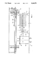
- FIG. 1 is a side view of the filtration plant of the invention
- FIG. 2 is a cross section through the filter plant of FIG. 1,
- FIG. 3 is an enlarged view of a portion of FIG. 2, shown partially in section,
- FIG. 4a is a cross section through the cleaning plant
- FIG. 4b is a horizontal section through the cleaning plant
- FIGS. 5a-f show the emptying of the filter press
- FIGS. 6a-g show the cleaning of the filter plates.
- the filtration plant comprises a filter press 1 having a press frame 2 consisting of a head stand 3, a cylinder stand 4 and spars 5a, 5b connecting the two of them.
- the cylinder stand 4 bears a push-piston drive 6 for the actuating of a press plate 7 which, in filter operation, presses a number of filter plates 8 covered with filter cloths together, each of said plates being supported by support grips 9a, 9b, on the spars 5a,b.
- FIG. 1 the filter press 1 is shown open.
- each of the parallelepiped housings 14 of the wash chambers 13a,b are suitable to receive one filter plate 8.
- Each of the wash chambers 13a,b contains a closed spray pipe 15 which is guided along the side walls and can be moved up and down by means of a surrounding drive 16, e.g. belt, chain, drive or similar, and is connected, via a valve 17, to a connection 18 which serves for the feeding of cleaning liquid.
- each of the wash chambers 13a, b is provided with a feed line 19 which is connected to a suction blower 23 and a drying blower 24 via valves 20 and 21 and 22, respectively.
- An outlet 25 serves for the discharge of spent cleaning liquid.
- a holding pedestal 26 serves for the dependable support of the filter plate 8 which is to be cleaned.
- the wash chambers 13a,b are watertight on the bottom and side walls so that they can also be filled with cleaning liquid.
- the two wash chambers 13a,b are arranged directly alongside of each other--their housings 14 have a wall in common. They also have a cover 27 in common, which cover can be pushed back and forth by a surrounding drive 28 between openings 29 on the topside of the wash chambers 13a,b so that it alternately closes one or the other of the openings 29.
- a transport device 30 comprises rails 31a,b which extend in the longitudinal direction of the filter press 1 and are suspended above the press as well as above the cleaning plant 12, said rails bearing a displacement device 32 which, provided with wheels 33 and driven via drive rods 34a,b, can be moved along the rails 31a,b.
- lift device 36 is anchored, having a gripper 37 which can be moved up and down by means of a chain drive 38.
- the gripper 37 has two arms 39a,b each of which bears a separating wedge 40 at its lower end and, alongside thereof, a driver finger 41, wedge and finger forming a downwardly open slot 42 between each other.
- the gripper 37 bears on top two gripper pawls 43a,b. Each of them has a lug 44 which is fastened to a support pipe 46 which is displaceable laterally by means of a push-piston drive 45.
- the press plate 7 When a given amount of sludge has been pumped through filter press 1 and the hollow spaces between the filter plates 8 have become filled with suspended matter, the press plate 7 is pulled away from the filter plates 8 by means of the push-piston drive 6.
- the displacement device 32 is advanced on the rails 31a,b from a position of rest (shown in dashed line in FIG. 1) into a position between the press plate 7 and the first of the filter plates 8 (FIG. 5a), and the gripper 37 is lowered (FIG. 5b).
- the displacement device 32 is then pushed further towards the filter plates 8 until the separation wedges 40, which are suspended resiliently on the arms 39a,b, come against the driver bolts 10a,b of the first filter plate 8a and align the filter plates 8 precisely transverse to the longitudinal direction (FIG. 5c).
- the gripper 37 is then raised slightly and the displacement device 32 is pushed forward so that the separation wedges 40 finally hold the center between the first filter plate 8a , and the second filter plate 8b (FIG. 5d).
- the gripper 37 is then lowered again so that the separation wedges 40 are pushed between the driver bolts 10a, b of the adjacent filter plates 8a,b and the latter are separated (FIG. 5e).
- the displacement device 32 is pushed against the press plate 7, it carrying the first filter plate 8a along with it via the separation wedges 40 and the driver bolts 10a,b until the filter plate 8a comes against the press plate 7 (FIG. 5f).
- the displacement device 32 is then set in motion in the direction towards the remaining filter plates 8 and again brought into the position shown in FIG. 5a.
- the gripper 37 is raised somewhat and the displacement device 32 displaced until the separation wedges 40 are in the center between the last filter plate 8z and the next to the last filter plate 8y.
- the gripper 37 is then lowered so that the separation wedges are pushed between the driver bolts 10a,b of the filter plates 8y, 8z and separate the latter.
- the driver bolts 10a,b of the last filter plate 8z then lie in the slot 42 formed between the separation wedge 40 and the drive finger 41, into which slot they fit with slight tolerance so that the position of the filter plate 8z is precisely controlled.
- the carrier pipes 46 of the gripper pawls 43a,b are now pulled inward (FIGS. 2, 3) by means of the lift piston drive 45 so that the lugs 44 are pushed over the carrier bolts 11a, b of the filter plate 8z.
- the gripper 37, together with the filter plate 8z, is then raised and finally the displacement device 32 is displaced (FIG. 6c) until it has arrived above the wash chamber 13a. In that position, the gripper 37 is lowered and the filter plate 8z is deposited on the holding pedestal 26 (FIG. 6d).
- the gripper pawls 43a,b are then pushed again into the unlocked position and the gripper 37 is lifted.
- the cover 27 is then pushed by the surrounding drive 28 from the position above the wash chamber 13b to a position above the wash chamber 13a, closing the opening 29 of the latter, and the filter plate 8z is cleaned.
- the next filter plate 8y is obtained from the filter press 1 by the displacement device 32, (FIG. 6e) and placed in the wash chamber 13b (FIG. 6f).
- the washing process in the wash chamber 13a has been completed in the meantime.
- the cover 27 is shifted from the wash chamber 13a to the wash cham-ber 13b, i.e. the former is opened and the latter is closed.
- the filter plate 8z is grasped by the gripper 37 in the wash chamber 13a in the manner already described, lifted and transported back to the filter press 1, where it is deposited (FIG. 6g) and pushed against the head stand 3.
- the displacement device 32 On its return path, the displacement device 32 carries the next filter plate along with it and deposits it for cleaning in the wash chamber 13a, and so on until all filter plates 8 are again present, cleaned, in the filter press 1, which is then closed by means of the press plate 7 and is ready for the next filtration cycle.
- the cleaning of a filter plate 8 is effected (FIG. 4a, b) in the manner that the valve 17 is opened and the filter plate 8 is sprayed with cleaning liquid--water, soap solution or the like--by the spray pipe 15 which surrounds it and is moved up and down.
- the spent cleaning liquid discharges through the outlet 25.
- the valves 20 and 21 are opened and the suction blower 23 is operated. In this way, the air in the wash chamber 13b, which contains a large amount of aerosols produced upon the spraying, is continuously withdrawn so that the aerosols cannot deposit again on the filter plate 8.
- the wash chambers 13a,b are so tightly closed that an exchange of gas with the region of the filter press 1, which could lead to contamination by aerosols of filter plates which have already been cleaned, is practically completely out of the question.
- the measures necessary are, of course, dependant on the field of use. Mere spatial separation of the cleaning plant 12 from the filter press 1 might also be sufficient.
- the filter plate 8 can be sprayed with other liquids, such as disinfectants or impregnating agents. Finally, filtered hot air is blown into the wash chamber 13b by the drying blower 24 via the valve 22--the valve 21 is closed at this time--and the filter plate 8 is dried.
- all of the steps enumerated are not always necessary. The selection depends on the application.
- the filter plate 8 can also be subjected to an immersion bath in the manner that the water-tight housing 14 of the wash chamber 13b is completely filled with cleaning liquid.
Landscapes
- Chemical & Material Sciences (AREA)
- Chemical Kinetics & Catalysis (AREA)
- Engineering & Computer Science (AREA)
- Environmental & Geological Engineering (AREA)
- Filtration Of Liquid (AREA)
- Filtering Materials (AREA)
- Separation By Low-Temperature Treatments (AREA)
- Electrical Discharge Machining, Electrochemical Machining, And Combined Machining (AREA)
- Cyclones (AREA)
Applications Claiming Priority (2)
| Application Number | Priority Date | Filing Date | Title |
|---|---|---|---|
| CH51391 | 1991-02-20 | ||
| CH513/91 | 1991-02-20 |
Publications (1)
| Publication Number | Publication Date |
|---|---|
| US5246578A true US5246578A (en) | 1993-09-21 |
Family
ID=4188726
Family Applications (1)
| Application Number | Title | Priority Date | Filing Date |
|---|---|---|---|
| US07/834,671 Expired - Fee Related US5246578A (en) | 1991-02-20 | 1992-02-11 | Filter press and cleaning means therefor |
Country Status (5)
| Country | Link |
|---|---|
| US (1) | US5246578A (ja) |
| EP (1) | EP0499859B1 (ja) |
| JP (1) | JPH0557111A (ja) |
| AT (1) | ATE122912T1 (ja) |
| DE (1) | DE59202276D1 (ja) |
Cited By (7)
| Publication number | Priority date | Publication date | Assignee | Title |
|---|---|---|---|---|
| US6641726B1 (en) * | 1998-11-12 | 2003-11-04 | H. Strassburger Gmbh & Co. Kg | Filter device, and filtration and cleaning method |
| US20030217691A1 (en) * | 2002-03-05 | 2003-11-27 | Erwin Hihn | Installation for coating objects with powder |
| WO2003068271A3 (en) * | 2002-02-14 | 2003-12-11 | Benesi Steve C | Pressure filter apparatus |
| US20050199559A1 (en) * | 2004-03-09 | 2005-09-15 | Duby Sean R. | Filter plate assembly for filter |
| CN109731379A (zh) * | 2019-03-07 | 2019-05-10 | 方凌晨 | 一种制药剂专用板框压滤装置 |
| WO2021223258A1 (zh) * | 2020-05-07 | 2021-11-11 | 南京山河环境科技有限公司 | 一种用于污泥脱水的压滤装置及其工作方法 |
| WO2023101860A1 (en) * | 2021-12-02 | 2023-06-08 | Benesi Steve C | Filter apparatus and filtering method |
Families Citing this family (9)
| Publication number | Priority date | Publication date | Assignee | Title |
|---|---|---|---|---|
| US6826874B2 (en) | 1999-06-30 | 2004-12-07 | Nippon Steel Corporation | Buckling restrained braces and damping steel structures |
| US7305799B2 (en) | 2002-05-29 | 2007-12-11 | Sme Steel Contractors, Inc. | Bearing brace apparatus |
| US7174680B2 (en) | 2002-05-29 | 2007-02-13 | Sme Steel Contractors, Inc. | Bearing brace apparatus |
| US7225588B2 (en) | 2003-07-08 | 2007-06-05 | Nippon Steel Corporation | Damping brace and structure |
| US7185462B1 (en) | 2003-07-25 | 2007-03-06 | Sme Steel Contractors, Inc. | Double core brace |
| CN110075582A (zh) * | 2019-04-02 | 2019-08-02 | 合肥皖航机电科技有限公司 | 一种板框过滤器 |
| CN111497174B (zh) * | 2020-04-19 | 2022-01-11 | 广西膜宝包科技发展有限公司 | 一种塑料吹塑自动换网结构的工作方法及其对接装置 |
| EP4015060B1 (de) | 2020-12-16 | 2024-01-03 | Filtrox AG | Vorrichtungen und verfahren zum reinigen von filterplatten eines filterpakets, filteranlagen und verfahren zum aufrüsten von filteranlagen |
| DE102023113327A1 (de) * | 2023-05-22 | 2024-11-28 | Strassburger Filter Gmbh & Co. Kg | Maschinensystem mit Filterpresse und Entnahmevorrichtung |
Citations (3)
| Publication number | Priority date | Publication date | Assignee | Title |
|---|---|---|---|---|
| US2442272A (en) * | 1944-03-21 | 1948-05-25 | Jaffa Mose | Degreasing apparatus embodying means for confining solvent vapor |
| US4172792A (en) * | 1977-05-31 | 1979-10-30 | Heinrich Hans J | Movable apparatus for removal of filter plates from a filter press |
| US4289618A (en) * | 1978-05-30 | 1981-09-15 | Eberhard Hoesch & Sohne Gmbh & Co. | Motion control for a filter press |
Family Cites Families (4)
| Publication number | Priority date | Publication date | Assignee | Title |
|---|---|---|---|---|
| US3216429A (en) * | 1964-01-22 | 1965-11-09 | Charles W Dick | Device for cleaning the throw away type of air filters of automobiles |
| DE2627578C2 (de) * | 1976-06-19 | 1984-01-05 | Rittershaus & Blecher Gmbh, 5600 Wuppertal | Filterpresse mit einer Abspritzeinrichtung |
| US4299245A (en) * | 1980-04-21 | 1981-11-10 | Clapper Millard F | Filter cleaning system |
| DE3816886A1 (de) * | 1988-05-18 | 1989-11-23 | Passavant Werke | Plattenfilterpresse |
-
1992
- 1992-01-31 AT AT92101596T patent/ATE122912T1/de not_active IP Right Cessation
- 1992-01-31 DE DE59202276T patent/DE59202276D1/de not_active Expired - Fee Related
- 1992-01-31 EP EP92101596A patent/EP0499859B1/de not_active Expired - Lifetime
- 1992-02-11 US US07/834,671 patent/US5246578A/en not_active Expired - Fee Related
- 1992-02-20 JP JP4033005A patent/JPH0557111A/ja active Pending
Patent Citations (3)
| Publication number | Priority date | Publication date | Assignee | Title |
|---|---|---|---|---|
| US2442272A (en) * | 1944-03-21 | 1948-05-25 | Jaffa Mose | Degreasing apparatus embodying means for confining solvent vapor |
| US4172792A (en) * | 1977-05-31 | 1979-10-30 | Heinrich Hans J | Movable apparatus for removal of filter plates from a filter press |
| US4289618A (en) * | 1978-05-30 | 1981-09-15 | Eberhard Hoesch & Sohne Gmbh & Co. | Motion control for a filter press |
Cited By (21)
| Publication number | Priority date | Publication date | Assignee | Title |
|---|---|---|---|---|
| US6641726B1 (en) * | 1998-11-12 | 2003-11-04 | H. Strassburger Gmbh & Co. Kg | Filter device, and filtration and cleaning method |
| US7531086B2 (en) * | 2002-02-14 | 2009-05-12 | Flsmidth A/S | Pressure filter apparatus |
| WO2003068271A3 (en) * | 2002-02-14 | 2003-12-11 | Benesi Steve C | Pressure filter apparatus |
| US20060102545A1 (en) * | 2002-02-14 | 2006-05-18 | Benesi Steve C | Pressure filter apparatus |
| US20030217691A1 (en) * | 2002-03-05 | 2003-11-27 | Erwin Hihn | Installation for coating objects with powder |
| US6723169B2 (en) * | 2002-03-05 | 2004-04-20 | Eisenmann Maschinenbau Kg | Installation for coating objects with powder |
| US20100219140A1 (en) * | 2004-03-09 | 2010-09-02 | Duby Sean R | Filter plate assembly for filter |
| US8366928B2 (en) | 2004-03-09 | 2013-02-05 | Duby Sean R | Filter plate assembly for filter |
| US7396472B2 (en) | 2004-03-09 | 2008-07-08 | Duby Sean R | Filter plate assembly for filter |
| US7569151B2 (en) | 2004-03-09 | 2009-08-04 | Duby Sean R | Filter plate assembly for filter |
| US20050199559A1 (en) * | 2004-03-09 | 2005-09-15 | Duby Sean R. | Filter plate assembly for filter |
| US7998354B2 (en) * | 2004-03-09 | 2011-08-16 | Duby Sean R | Filter press with improved plate assembly and method of filtering |
| US8287741B2 (en) | 2004-03-09 | 2012-10-16 | Duby Sean R | Filter plate assembly for filter |
| US20080264879A1 (en) * | 2004-03-09 | 2008-10-30 | Duby Sean R | Filter plate assembly for filter |
| US9023201B2 (en) | 2004-03-09 | 2015-05-05 | Sean R. Duby | Filter plate assembly for filter |
| US20150336032A1 (en) * | 2004-03-09 | 2015-11-26 | Sean R. Duby | Filter plate assembly for filter |
| US9981210B2 (en) * | 2004-03-09 | 2018-05-29 | Sean R. Duby | Filter plate assembly for filter |
| US10905977B2 (en) | 2004-03-09 | 2021-02-02 | Sean R. Duby | Filter plate assembly for filter |
| CN109731379A (zh) * | 2019-03-07 | 2019-05-10 | 方凌晨 | 一种制药剂专用板框压滤装置 |
| WO2021223258A1 (zh) * | 2020-05-07 | 2021-11-11 | 南京山河环境科技有限公司 | 一种用于污泥脱水的压滤装置及其工作方法 |
| WO2023101860A1 (en) * | 2021-12-02 | 2023-06-08 | Benesi Steve C | Filter apparatus and filtering method |
Also Published As
| Publication number | Publication date |
|---|---|
| EP0499859B1 (de) | 1995-05-24 |
| JPH0557111A (ja) | 1993-03-09 |
| DE59202276D1 (de) | 1995-06-29 |
| EP0499859A1 (de) | 1992-08-26 |
| ATE122912T1 (de) | 1995-06-15 |
Similar Documents
| Publication | Publication Date | Title |
|---|---|---|
| US5246578A (en) | Filter press and cleaning means therefor | |
| SE437336B (sv) | Forfarande for avskiljning av partiklar ur en strommande fluid i tre kontinuerligt upprepade arbetsfaser och anordning derfor | |
| CN116850667B (zh) | 一种乳清蛋白分离提纯装置 | |
| US2326484A (en) | Filtering apparatus | |
| US20080072938A1 (en) | Lift/immersion bath | |
| CN216679334U (zh) | 一种配药框清洗机 | |
| US20160303624A1 (en) | Chemcial jug washer and disposal assembly | |
| US20070204886A1 (en) | Lift/immersion bath | |
| US3458275A (en) | Material handling container and method for using the same | |
| KR100444977B1 (ko) | 집수조 청소차량 | |
| KR100595091B1 (ko) | 세정장치 | |
| CN219648252U (zh) | 一种样瓶自动清洗烘干系统 | |
| CN114392979B (zh) | 一种配药框清洗机 | |
| CN218982610U (zh) | 一种煎药容器预翻式清洗装置 | |
| KR101904645B1 (ko) | 세정 및 린스공정을 수행할 수 있는 산업용 세척기 | |
| CN222770720U (zh) | 一种水处理用板式水处理设备 | |
| JPH04310841A (ja) | 染色装置と染色用トレー | |
| EP0603975A1 (en) | A method and a device for cleaning containers | |
| JPS62114663A (ja) | 固定層式イオン交換器の再浄化方法及び装置 | |
| CN217367345U (zh) | 一种便于清理的市政污水处理杂物过滤器 | |
| JPH0652977U (ja) | 洗浄装置 | |
| JP2813861B2 (ja) | 洗浄装置 | |
| CN215785276U (zh) | 一种喷淋式清洗机械设备 | |
| CN219126130U (zh) | 环形多工位洗菜机 | |
| JPH0532185Y2 (ja) |
Legal Events
| Date | Code | Title | Description |
|---|---|---|---|
| AS | Assignment |
Owner name: VON ROLL AG, SWITZERLAND Free format text: ASSIGNMENT OF ASSIGNORS INTEREST.;ASSIGNORS:SPIEGEL, PETER;KACH, HANS;REEL/FRAME:006078/0859 Effective date: 19920318 |
|
| AS | Assignment |
Owner name: BERTRAMS DEHYDRAT AG, SWITZERLAND Free format text: ASSIGNMENT OF ASSIGNORS INTEREST;ASSIGNOR:VON ROLL HOLDING AG;REEL/FRAME:008167/0134 Effective date: 19951214 |
|
| FEPP | Fee payment procedure |
Free format text: PAT HOLDER CLAIMS SMALL ENTITY STATUS - SMALL BUSINESS (ORIGINAL EVENT CODE: SM02); ENTITY STATUS OF PATENT OWNER: SMALL ENTITY |
|
| AS | Assignment |
Owner name: BERTRAMS AG, SWITZERLAND Free format text: CORRECTIVE ASSIGNMENT TO CORRECT NAME ON ASSIGNMENT RECORDED OCTOBER 7, 1996 AT REEL 8167, FRAME 0134;ASSIGNOR:VON ROLL HOLDING AG;REEL/FRAME:008366/0835 Effective date: 19951214 |
|
| REMI | Maintenance fee reminder mailed | ||
| FPAY | Fee payment |
Year of fee payment: 4 |
|
| SULP | Surcharge for late payment | ||
| FEPP | Fee payment procedure |
Free format text: PAYOR NUMBER ASSIGNED (ORIGINAL EVENT CODE: ASPN); ENTITY STATUS OF PATENT OWNER: SMALL ENTITY |
|
| FPAY | Fee payment |
Year of fee payment: 8 |
|
| REMI | Maintenance fee reminder mailed | ||
| LAPS | Lapse for failure to pay maintenance fees | ||
| STCH | Information on status: patent discontinuation |
Free format text: PATENT EXPIRED DUE TO NONPAYMENT OF MAINTENANCE FEES UNDER 37 CFR 1.362 |
|
| FP | Lapsed due to failure to pay maintenance fee |
Effective date: 20050921 |