US5281071A - Portable ice storage and dispensing system - Google Patents
Portable ice storage and dispensing system Download PDFInfo
- Publication number
- US5281071A US5281071A US07/959,199 US95919992A US5281071A US 5281071 A US5281071 A US 5281071A US 95919992 A US95919992 A US 95919992A US 5281071 A US5281071 A US 5281071A
- Authority
- US
- United States
- Prior art keywords
- auger
- traversing
- rack
- storage bin
- tail
- Prior art date
- Legal status (The legal status is an assumption and is not a legal conclusion. Google has not performed a legal analysis and makes no representation as to the accuracy of the status listed.)
- Expired - Fee Related
Links
Images


Classifications
-
- B—PERFORMING OPERATIONS; TRANSPORTING
- B65—CONVEYING; PACKING; STORING; HANDLING THIN OR FILAMENTARY MATERIAL
- B65G—TRANSPORT OR STORAGE DEVICES, e.g. CONVEYORS FOR LOADING OR TIPPING, SHOP CONVEYOR SYSTEMS OR PNEUMATIC TUBE CONVEYORS
- B65G65/00—Loading or unloading
- B65G65/30—Methods or devices for filling or emptying bunkers, hoppers, tanks, or like containers, of interest apart from their use in particular chemical or physical processes or their application in particular machines, e.g. not covered by a single other subclass
- B65G65/34—Emptying devices
- B65G65/40—Devices for emptying otherwise than from the top
- B65G65/46—Devices for emptying otherwise than from the top using screw conveyors
- B65G65/466—Devices for emptying otherwise than from the top using screw conveyors arranged to be movable
-
- F—MECHANICAL ENGINEERING; LIGHTING; HEATING; WEAPONS; BLASTING
- F25—REFRIGERATION OR COOLING; COMBINED HEATING AND REFRIGERATION SYSTEMS; HEAT PUMP SYSTEMS; MANUFACTURE OR STORAGE OF ICE; LIQUEFACTION SOLIDIFICATION OF GASES
- F25C—PRODUCING, WORKING OR HANDLING ICE
- F25C5/00—Working or handling ice
- F25C5/20—Distributing ice
- F25C5/24—Distributing ice for storing bins
Definitions
- the present invention relates to preparing fresh food products such as fish or produce for shipment from the site of harvesting to market, and more particularly, to a method and apparatus for providing easily movable and quickly erectable portable large capacity bins for bulk storage and dispensing of ice or other similar materials.
- the storage component of a typical ice system takes on more importance by providing the ability to generate ice during "off-peak” periods and to utilize the inventory of ice from the storage during "on-peak” periods.
- This form of thermal energy storage can reduce on-peak electrical load to near 90%.
- ice rakes are positioned horizontally on an ice mass within the ice storage bin and serve to remove the fragmentary ice from the top of the pile to a discharge conveyor.
- Such systems have the disadvantage that they require considerable overhead clearance for the pulleys, cables, and motors required to maintain the ice rake in a horizontal position and to control the movement of the ice rake.
- such devices typically require a cumbersome counterweight movement mechanism in order to raise the ice rake to refill the bin with a new supply of fragmentary ice.
- bin unloading systems have been proposed for materials other than fragmentary ice; however, many of them are inappropriate for use in the sanitary environment required for the storage and handling of ice.
- many of the conveying devices used for other materials have motors and gears located within the storage bin, which could lead to the introduction of grease or other impurities into the ice bin. Bin unloading systems such as these are therefore inappropriate for use in bulk ice storage bins.
- the present invention relates to a low cost unitary ice bin and conveying structure.
- the storage structure disclosed herein is designed to make optimum use of a limited amount of space.
- Portable storage bins according to this invention are designed so that they may be prefabricated and assembled for use in the intended storage area. Manufacturing and assembly costs are therefore low.
- the apparatus of the present invention is simple to operate and requires little maintenance. It is the purpose of this invention to provide a very fast set-up and knock-down system for short duration use, obtaining all of the advantages of safety, sanitation, energy conservation and reduction of water use while at the same time, reducing capital and operating costs to the user.
- the present invention is an ice storage system which allows for quick assembly and disassembly, and which receives ice through the top.
- the ice storage system comprises a bin having a plurality of wall panels quick-fastened to corner posts, which are secured to a foundation frame.
- An ice mass within the bin is located over a traversing auger with opposite hand flighting which both traverses and rotates under the ice mass, cutting the ice and conveying the cut ice towards the center and into a discharge conveyor which then ejects the ice to the exterior of the bin. After a near full traverse, the ice mass falls, and the traversing direction is reversed cutting and conveying the ice into the discharge conveyor.
- FIG. 1 is a pictorial diagram of an ice storage and dispensing system in accordance with the present invention.
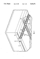
- FIG. 2 is a perspective view, partly broken away, of an embodiment of a portable ice storage bin in accordance with the present invention.
- FIG. 3 is a perspective view of a discharge end base for the ice storage bin of FIG. 2.
- FIG. 4 is a fragmentary sectional side view showing a mounting detail for the head carriage of the ice storage bin of FIG. 2.
- FIG. 6 is a perspective view of a second embodiment of a portable ice storage bin in accordance with the invention.
- FIG. 7 is a perspective view within the bin of FIG. 6 showing the traversing auger and the discharge conveyor.
- the wall panels 12 may be made of metal or of 4 ⁇ 8 foot plywood panels, or the like, that present a smooth surface to the interior of the storage bin 11, while the corner posts 13 are made of metal. If plywood panels are used, they provide some thermal insulation for the ice. In either case, some additional thermal insulation such as polyurethane or the like may be attached.
- the wall panels 12 are mounted to rectangular frames 20 having quick-connect fasteners 21 that snap into notches 22 provided in the corner posts 13.
- the foundation frame 14 is made of a sturdy metal such as steel, and is provided with pre-punched attachment holes.
- the foundation frame 14 comprises a head rack base 23, and a tail rack base 24. These two portions of the foundation frame 14 carry the bulk of the load, and are formed using heavy steel I-beams, and the like.
- the corner posts 13 are fastened to the head rack base 23 and to the tail rack base 24.
- the foundation frame 14 also comprises a drive end base 25 and a discharge end base 26 (FIG. 3).
- the head rack base 23 has mounted thereon an elongated, toothed head rack 30.
- the tail rack base 23 has mounted thereon a similar elongated toothed tail rack 31.
- the traversing auger 15 has a head gear 32 affixed to the head end thereof and engaged with the teeth of the head rack 30.
- the tail end of the traversing auger 15 has a tail gear 33 affixed thereto and engaged with the teeth of the tail rack 31.
- the head end of the traversing auger 15 and the head gear 32 are mounted to a head carriage 34, while the tail end of the traversing auger 15 and the tail gear 33 are mounted to a tail carriage 35.
- the head carriage 34 is movably mounted for travel along the head rack base 23, and the tail carriage 35 is movably mounted for travel along the tail rack base 24.
- the head carriage 34 is provided with a drive mechanism 36 including motors 37 for rotating the traversing auger 15 and for causing the traversing auger 15 to travel the length of the storage bin 11 in both directions.
- FIG. 4 there is shown a detail drawing of the manner of movably mounting the head carriage 34 for travel along the head rack base 23.
- the head rack base 23 has affixed to it an I-beam 27 that supports the head rack 30.
- the head carriage 34 is provided with rollers 28 that roll along the I-beam 27 as the carriage 34 moves.
- the tail carriage 35 is similarly mounted.
- the upper motor 37 drives the chain that rotates the traversing auger 15, while the lower motor 37 drives the head gear 32 that causes the traversing auger 15 to travel the length of the head rack 30 in both directions.
- the discharge conveyor 16 is provided with a drive motor 38 shown disposed on the drive end base 25 in FIG. 5.
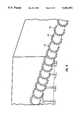
- the traversing auger 15 is provided with opposite hand helical flighting 40 and cutting teeth (not shown) for undercutting the ice mass 19 within the storage bin 11.
- the helical flighting carries the cut ice toward the center to the discharge conveyor 16. It will be understood that opposite hand helical flighting means that on one side of the center, the helix is a left hand helix, and on the other side of the center, the helix is a right hand helix. This means that each side of the traversing auger 15 brings the cut ice to the center and deposits it in the discharge conveyor 16.
- the discharge conveyor 16 is provided with a simple conveyor helix 41 for conveying the cut ice to the exterior of the bin 11.
- FIG. 7 is a perspective view of the interior of the bin 100 looking toward the head carriage 112.
- the head carriage 112 and the rack 106 may be seen through the elongated opening 107.
- the interior of the wall panels 101 may be seen above the head rack base 104 and the discharge end base 105.
- Braces 116 are provided extending diagonally from corner to corner of the bin 100, and are tightened with turnbuckles (not shown).
- a discharge conveyor 117 may be seen extending toward the discharge outlet 118 in the discharge end base 105.
- the traversing auger 110 has opposite hand helical flighting 119 and cutting teeth 120.
- FIG. 8 is a perspective view of the traversing auger 110. In this view, the helical flighting 119 and the cutting teeth 120 may be more clearly seen.
- the present invention employs a traversing auger with opposite hand flighting which both traverses and rotates under an ice mass within a bin, thereby cutting the ice and conveying the cut ice toward the center and into a discharge conveyor which then ejects the ice to the exterior of the bin. After a near full traverse, the ice mass falls, and the traversing direction is reversed.
- the ice storage bin of the present invention provides efficient, sanitary unloading of fragmentary ice that has fused together. It is suitable for use at the site of harvesting, is easily movable and quickly erectable.
Landscapes
- Engineering & Computer Science (AREA)
- Mechanical Engineering (AREA)
- Physics & Mathematics (AREA)
- Thermal Sciences (AREA)
- General Engineering & Computer Science (AREA)
- Filling Or Emptying Of Bunkers, Hoppers, And Tanks (AREA)
- Devices For Post-Treatments, Processing, Supply, Discharge, And Other Processes (AREA)
Priority Applications (3)
| Application Number | Priority Date | Filing Date | Title |
|---|---|---|---|
| US07/959,199 US5281071A (en) | 1992-10-09 | 1992-10-09 | Portable ice storage and dispensing system |
| CA002107964A CA2107964C (fr) | 1992-10-09 | 1993-10-07 | Systeme portatif de stockage et de distribution de glace |
| MX9306267A MX9306267A (es) | 1992-10-09 | 1993-10-08 | Sistema para almacenar y surtir hielo portatil. |
Applications Claiming Priority (1)
| Application Number | Priority Date | Filing Date | Title |
|---|---|---|---|
| US07/959,199 US5281071A (en) | 1992-10-09 | 1992-10-09 | Portable ice storage and dispensing system |
Publications (1)
| Publication Number | Publication Date |
|---|---|
| US5281071A true US5281071A (en) | 1994-01-25 |
Family
ID=25501768
Family Applications (1)
| Application Number | Title | Priority Date | Filing Date |
|---|---|---|---|
| US07/959,199 Expired - Fee Related US5281071A (en) | 1992-10-09 | 1992-10-09 | Portable ice storage and dispensing system |
Country Status (3)
| Country | Link |
|---|---|
| US (1) | US5281071A (fr) |
| CA (1) | CA2107964C (fr) |
| MX (1) | MX9306267A (fr) |
Cited By (6)
| Publication number | Priority date | Publication date | Assignee | Title |
|---|---|---|---|---|
| WO1997029330A1 (fr) * | 1996-02-12 | 1997-08-14 | Tmo Enterprises Limited | Appareil distributeur |
| US5761888A (en) * | 1996-09-19 | 1998-06-09 | Carbonic Industries Corporation | Method and apparatus for conveying dry ice |
| US6585472B2 (en) * | 1999-02-23 | 2003-07-01 | Henderson Manufacturing Company | Combination dump and spreader apparatus |
| US20060034961A1 (en) * | 2002-07-18 | 2006-02-16 | Starlinger & Co. G.M.B.H. | Device for processing plastic waste |
| US20080199287A1 (en) * | 2007-02-16 | 2008-08-21 | Martens Christoph | Storage and/or transport container for bulk material, especially push-bottom bunker |
| WO2008148427A1 (fr) * | 2007-06-06 | 2008-12-11 | Otto-Wilhelm Held | Dispositif de stockage de glace pour machine à glace |
Citations (6)
| Publication number | Priority date | Publication date | Assignee | Title |
|---|---|---|---|---|
| US3212652A (en) * | 1963-04-09 | 1965-10-19 | John A Roberts | Storage apparatus |
| US4294176A (en) * | 1979-04-04 | 1981-10-13 | Brooks Albert C | Portable hoist frame |
| JPS60213631A (ja) * | 1984-04-04 | 1985-10-25 | Takeshi Hayashi | 砕氷の貯蔵庫 |
| US4717308A (en) * | 1983-12-14 | 1988-01-05 | E-Z Trail, Inc. | Container unloading system |
| US4733896A (en) * | 1986-03-11 | 1988-03-29 | Harsco Corporation | Lift container and method for using same |
| FR2611681A1 (fr) * | 1987-03-06 | 1988-09-09 | Morillon Sa | Procede et dispositif de reprise de talus residuels dans un silo rectangulaire a fond plat |
-
1992
- 1992-10-09 US US07/959,199 patent/US5281071A/en not_active Expired - Fee Related
-
1993
- 1993-10-07 CA CA002107964A patent/CA2107964C/fr not_active Expired - Fee Related
- 1993-10-08 MX MX9306267A patent/MX9306267A/es not_active IP Right Cessation
Patent Citations (6)
| Publication number | Priority date | Publication date | Assignee | Title |
|---|---|---|---|---|
| US3212652A (en) * | 1963-04-09 | 1965-10-19 | John A Roberts | Storage apparatus |
| US4294176A (en) * | 1979-04-04 | 1981-10-13 | Brooks Albert C | Portable hoist frame |
| US4717308A (en) * | 1983-12-14 | 1988-01-05 | E-Z Trail, Inc. | Container unloading system |
| JPS60213631A (ja) * | 1984-04-04 | 1985-10-25 | Takeshi Hayashi | 砕氷の貯蔵庫 |
| US4733896A (en) * | 1986-03-11 | 1988-03-29 | Harsco Corporation | Lift container and method for using same |
| FR2611681A1 (fr) * | 1987-03-06 | 1988-09-09 | Morillon Sa | Procede et dispositif de reprise de talus residuels dans un silo rectangulaire a fond plat |
Cited By (6)
| Publication number | Priority date | Publication date | Assignee | Title |
|---|---|---|---|---|
| WO1997029330A1 (fr) * | 1996-02-12 | 1997-08-14 | Tmo Enterprises Limited | Appareil distributeur |
| US5761888A (en) * | 1996-09-19 | 1998-06-09 | Carbonic Industries Corporation | Method and apparatus for conveying dry ice |
| US6585472B2 (en) * | 1999-02-23 | 2003-07-01 | Henderson Manufacturing Company | Combination dump and spreader apparatus |
| US20060034961A1 (en) * | 2002-07-18 | 2006-02-16 | Starlinger & Co. G.M.B.H. | Device for processing plastic waste |
| US20080199287A1 (en) * | 2007-02-16 | 2008-08-21 | Martens Christoph | Storage and/or transport container for bulk material, especially push-bottom bunker |
| WO2008148427A1 (fr) * | 2007-06-06 | 2008-12-11 | Otto-Wilhelm Held | Dispositif de stockage de glace pour machine à glace |
Also Published As
| Publication number | Publication date |
|---|---|
| CA2107964A1 (fr) | 1994-04-10 |
| CA2107964C (fr) | 2001-10-16 |
| MX9306267A (es) | 1994-07-29 |
Similar Documents
| Publication | Publication Date | Title |
|---|---|---|
| US2735591A (en) | E branchflower | |
| EP0431207A1 (fr) | Appareil pour la production, la distribution, la mise en sac et le stockage de glaçons transparents | |
| US5281071A (en) | Portable ice storage and dispensing system | |
| AU661019B2 (en) | Device and method for outloading bulk materials | |
| US4371305A (en) | Material handling apparatus | |
| US4612779A (en) | Mobile ice plant | |
| US5449263A (en) | Device and method for torque assist of drag arm | |
| EP1869376A1 (fr) | Procede et dispositif de production de glace | |
| CN217625930U (zh) | 一种粗料仓装置 | |
| US4541252A (en) | Mechanized self evacuating fragmentary ice storage bin | |
| US3279436A (en) | Rotary discharge livestock feeder | |
| CN222006652U (zh) | 一种装车楼用整平结构 | |
| US3093110A (en) | Silo unloading apparatus | |
| FI70551B (fi) | Skrapanordning | |
| AU668514B2 (en) | Device and method for outloading bulk materials | |
| US3490615A (en) | High density,high efficiency storage building for free flowing materials | |
| EP1955583A1 (fr) | Remorque de distribution | |
| DE249761C (fr) | ||
| US20020064868A1 (en) | Partitioned composting cage | |
| CN218057532U (zh) | 一种可转场散状物料堆料机 | |
| SU1706491A1 (ru) | Кормораздатчик | |
| CN210552180U (zh) | 一种基于混泥土搅拌泵的防堵塞料斗 | |
| SU1556622A1 (ru) | Устройство дл хранени сыпучих материалов | |
| SU1644843A1 (ru) | Кормораздатчик | |
| DE2052628C3 (de) | Entladevorrichtung für einen abgeschlossenen Speicher |
Legal Events
| Date | Code | Title | Description |
|---|---|---|---|
| AS | Assignment |
Owner name: POST-HARVEST TECHNOLOGIES, INC., CALIFORNIA Free format text: ASSIGNMENT OF ASSIGNORS INTEREST.;ASSIGNOR:CRABB, RICHARD V. JR.;REEL/FRAME:006318/0423 Effective date: 19921111 |
|
| FPAY | Fee payment |
Year of fee payment: 4 |
|
| FEPP | Fee payment procedure |
Free format text: PAT HLDR NO LONGER CLAIMS SMALL ENT STAT AS SMALL BUSINESS (ORIGINAL EVENT CODE: LSM2); ENTITY STATUS OF PATENT OWNER: LARGE ENTITY |
|
| FPAY | Fee payment |
Year of fee payment: 8 |
|
| REMI | Maintenance fee reminder mailed | ||
| LAPS | Lapse for failure to pay maintenance fees | ||
| STCH | Information on status: patent discontinuation |
Free format text: PATENT EXPIRED DUE TO NONPAYMENT OF MAINTENANCE FEES UNDER 37 CFR 1.362 |
|
| FP | Lapsed due to failure to pay maintenance fee |
Effective date: 20060125 |