US5296909A - Detector of suspended cables for avionic applications - Google Patents
Detector of suspended cables for avionic applications Download PDFInfo
- Publication number
- US5296909A US5296909A US07/854,639 US85463992A US5296909A US 5296909 A US5296909 A US 5296909A US 85463992 A US85463992 A US 85463992A US 5296909 A US5296909 A US 5296909A
- Authority
- US
- United States
- Prior art keywords
- scan
- laser beam
- reflection data
- search path
- raster
- Prior art date
- Legal status (The legal status is an assumption and is not a legal conclusion. Google has not performed a legal analysis and makes no representation as to the accuracy of the status listed.)
- Expired - Fee Related
Links
- 238000001514 detection method Methods 0.000 claims description 37
- 239000011159 matrix material Substances 0.000 claims description 16
- 210000004883 areola Anatomy 0.000 claims description 9
- 238000012545 processing Methods 0.000 claims description 3
- 230000003287 optical effect Effects 0.000 abstract description 11
- 230000010006 flight Effects 0.000 abstract 1
- 238000000034 method Methods 0.000 description 7
- 230000005855 radiation Effects 0.000 description 4
- 230000000875 corresponding effect Effects 0.000 description 3
- 238000011156 evaluation Methods 0.000 description 3
- 230000006870 function Effects 0.000 description 3
- 238000004364 calculation method Methods 0.000 description 2
- 238000010586 diagram Methods 0.000 description 2
- 230000002093 peripheral effect Effects 0.000 description 2
- 230000008569 process Effects 0.000 description 2
- 238000012360 testing method Methods 0.000 description 2
- 241000723353 Chrysanthemum Species 0.000 description 1
- 235000005633 Chrysanthemum balsamita Nutrition 0.000 description 1
- 241000220317 Rosa Species 0.000 description 1
- 230000008901 benefit Effects 0.000 description 1
- 238000006243 chemical reaction Methods 0.000 description 1
- 230000002596 correlated effect Effects 0.000 description 1
- 230000001934 delay Effects 0.000 description 1
- 238000013461 design Methods 0.000 description 1
- 238000002592 echocardiography Methods 0.000 description 1
- 238000000605 extraction Methods 0.000 description 1
- 238000001914 filtration Methods 0.000 description 1
- 230000003993 interaction Effects 0.000 description 1
- 230000009467 reduction Effects 0.000 description 1
- 230000004044 response Effects 0.000 description 1
- 230000003595 spectral effect Effects 0.000 description 1
- XLYOFNOQVPJJNP-UHFFFAOYSA-N water Substances O XLYOFNOQVPJJNP-UHFFFAOYSA-N 0.000 description 1
Images

Classifications
-
- G—PHYSICS
- G01—MEASURING; TESTING
- G01S—RADIO DIRECTION-FINDING; RADIO NAVIGATION; DETERMINING DISTANCE OR VELOCITY BY USE OF RADIO WAVES; LOCATING OR PRESENCE-DETECTING BY USE OF THE REFLECTION OR RERADIATION OF RADIO WAVES; ANALOGOUS ARRANGEMENTS USING OTHER WAVES
- G01S17/00—Systems using the reflection or reradiation of electromagnetic waves other than radio waves, e.g. lidar systems
- G01S17/88—Lidar systems specially adapted for specific applications
- G01S17/93—Lidar systems specially adapted for specific applications for anti-collision purposes
- G01S17/933—Lidar systems specially adapted for specific applications for anti-collision purposes of aircraft or spacecraft
Definitions
- This invention concerns a suspended cable detector specially suited for avionic applications. It is well known that some risks are encountered mainly by light aircrafts and helicopters when they are flying in areas traversed by suspended cables.
- the scope of this invention is of supplying the aircraft pilot with a warning system which, when suspended cables are present, allows the immediate selection of the evasive move to be effected.
- This alarm is the result of a very effective and reliable scan of the search area and of an extractor which can generate in time the alarm signal and supply the data related to the position parameters of the detected suspended cable.
- a scan type which may be defined as "quasi-random" is proposed in the invention which is the subject of this patent application.
- the scan parameters are so selected that the search area is divided into many signal small areas equal in number to the Lidar PRF (Pulse Repetition Frequency) if the scan time is one second.
- Lidar PRF Pulse Repetition Frequency
- At the center of each areola a Lidar spot is located. Only a small portion of this areola is covered by the spot due to its dimensions.
- the spots are anything but adjacent or superposed as in the scan types above montioned.
- the areolas may have equal or different dimensions so that consequently the spots may be concentrated in zones where the maximum performance is requested.
- the scan so far obtained is not very much effective to detect cables since the Lidar shots are concentrated along a limited number of diagonals inside the search area.
- the bandwidth of the random movement must be such as to reduce to a minimum the correlation between the position of two successive spots inside their areolas; the bandwidth must also be compatible with the response bandwidth of the scan servos.
- the scan may be greatly simplified. For instance if vertical cables in the search area are excluded the random movement in the Azimuth direction may be reduced or suppressed.
- the cable detection is in general committed to the operator eye or to simple computing systems which identify a set of Lidar intercepts lined up in the Azimuth/Elevation plane.
- the performance of such identification systems is very poorly effective in respect of the number of target intercepts and becomes even worse in presence of backgrounds which are targets at the same time.
- the proposed Automatic Extractor has a very good effectiveness in respect of the target intercept number. Only three intercepts may be sufficient to identify a suspended cable.
- the Extractor shows a good discrimination against false alarms both distributed (i.e. from generator random noise or from background) and concentrated (i.e. from reflecting continuous backgrounds as buildings, sheets of water etc.) which may be present in the search area.
- the Automatic Extractor is composed mainly of two parts: the background filter (7) and the chain extractor (8).
- the first is a fast digital device which, during each scan time, gathers the spatial data (Azimuth, Elevation, Distance) of each intercept, being stimulated by the optical receiver.
- the data are converted in a suitable coordinate system and are recorded in a memory called "detection matrix".
- This matrix contains the data set, related to the actual target status in the search area, gathered by Lidar in a scan time.
- the matrix is formed by the geometric parameters of the Lidar detection of each point.
- the background filter finds special correlations between the detections as a function of their relative positions in the geometric cartesian space. The aim is of reducing the influence of reflecting continuous backgrounds of no interest. In particular the above filter excludes from the detection matrix almost all the alarms coming from such backgrounds.
- the background filter calculates its distance from the already gathered detections (during the actual scan time). All the detections whose distance is less than a given threshold (a few meters) are erased from the memory and the corresponding areas are made available for the collection of further detections. Therefore the filter, besides the effective reduction of the false alarm probability, greatly reduces the memory which stores the data to be used for the successive extraction process.
- the background effectiveness is greatly influenced by the type of scan. A scan of the Raster type gives the best results.
- the target status inside the search area referred to the last scan and stored in the detection matrix is transmitted to the chain extractor. Since a laser with a low PRF is used to limit the weight and dimensions of the device, the coverage of the search area is absolutely incomplete.
- the chain extractor takes advantage of the property of the intercepts generated by a cable. These intercepts are lying on well known curves as straight lines or stretches of catenary while false detections, caused by receiver noise or random background signals, are randomly distributed in space.
- the operation of the chain extractor may be divided into three phases:
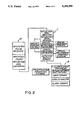
- FIGS. 1 and 2 show the main elements forming the system in a block diagram.
- the scan system S is composed of:
- the Lidar assy is composed of:
- the Extractor assy is mainly formed by:
- the noise generator (1) is a low frequency (audio band) random voltage (or current) generator. It may be implemented by amplifying and filtering the shot noise produced by a resistor maintained at controlled temperature. This voltage is used by the scan device to break the deterministic relation between successive pointings which is typical of a conventional scan.
- the Raster generator (2) is formed by electric and electronic circuitry which generate the driving voltages of the electric actuators of the pointing optics. The basic voltages show the typical time function of a conventional scan like Raster. The two sawtooth voltages have repetition frequencies corresponding respectively to the line scan and frame scan frequencies. The frame repetition frequency is defined by the device updating specification which is usually one second.
- the line scan frequency which sets the spacing between the horizontal lines, and the scan average speed are so selected that the beam spots are uniformly distributed on the search area. This corresponds to divide the whole area into square elementary areolas equal in number to the Lidar PRF.
- the scan circuit then sums to the scan waveforms:
- the noise generator voltage so that the actual position of the spot becomes quasi-random inside the elementary areola.
- the scan concentrator voltage to slow down or speed up the scan motion in order to raise the spot number in the areas where an increased probability of target detection is needed.
- the scan concentrator (3) is composed of electronic circuits whose output is a variable amplitude voltage or current.
- the amplitude is a function of the actual spot position in accordance with the specified distribution of the target detection probability inside the search area.
- the aiming optics (4) and the angular actuator (10) form a mechanical assy that, at the reception of the scan commands, directs inside the search area the beams of the laser transmitter (5) and of the optical receiver (6) which have been properly superposed in advance.
- the beam deflection may be obtained by means of mirror and/or prism optical systems moved by electric motors or by beam deflectors based on acoustooptical interaction.
- the instantaneous beam position is measured by the angular restorer (11) composed, for instance, of two optical encoders and it is sent to the background filter which associates this information with the distance coming from the optical detector.
- the transmitter (5) is an assy formed by the laser radiation generator and its power supply. It works at a wavelength which shows a low attenuation by the atmosphere and it is safe to the eye.
- the radiation pulse PRF allows the coverage of the search area in less than one second with the scanning law imposed by the scan system.
- the pulses are sent to the pointing optics (4) through the beam splitter (9).
- the optical receiver (6) is composed mainly by a focusing optics, spatial and spectral filters, which suppress the background radiation, and by the sensing element with its electronic circuits.
- the target backscattered radiation is directed through the aiming optics (4) to the beam splitter (9) which provides for its sending to the input of the assembly.
- the receiver (6) by measuring the laser pulse time-of-flight, can evaluate the target distance. This value is sent to the background filter which provides for its further processing.
- the background filter (7) is a fast digital device which, by receiving signals from the optical receiver, performs the following operations:
- the detection matrix (M) by erasing step-by-step all the intercepts lying within a given distance from the last one. In this way owing to the used scan type (randomized raster) the intercepts due to the back echoes from building walls or other continous surfaces are practically suppressed. The dimensions of the memory which stores the detections and the probability of detecting non-existent cables are greatly reduced by the above method.
- the chain extractor is a fast digital computer which processes the detection matrix.
- the chain extractor (8) when receives the detection matrix from the background filter (7) carries out a process which may be divided into three parts:
- Composition of chains formed by the above groups, in the parameter space.
- the scan system S sends to the pointing optics the sawtooth signals modulated by the outputs of the noise generator (1) and scan concentrator (3).
- the aiming optics (4) provides for the pointing of the laser transmitter beam (5) inside the search area by means of the angular actuator.
- the angular restorer (11) sends the actual Azimuth/Elevation position to the background filter (7).
- the laser transmitter (5) generates pulses at the prefixed PRF which are sent to the pointing optics.
- the optical receiver (6) as soon as receives an echo which exceeds the threshold emits a detection signal and measures the target distance.
- the background filter (7) carries out the following operations on each detection and each measured distance.
- e3 stores the cartesian coordinates in the first available memory location.
- e4 calculates the distance, in the tridimensional space, between the actual detection and all the detections already stored in the memory.
- the extractor (8) performs three sets of operations on each detection matrix coming from the background filter (7) at the end of each scan period. These operations are:
- each chain is characterized by a forebear. All the points within a limited area around the forebear are associated to the same chain; point clusters in the parameters space are so identified.
- the cable position is determined by performing the Hough inverse transform on the average of the event parameters associated to the above chain.
- the most significant part of the invention resides in the system configutation which considers the introduction of a Lidar system between the scanning element and the extractor.
- This system may be represented at best by a product of their own design.
Landscapes
- Engineering & Computer Science (AREA)
- Physics & Mathematics (AREA)
- Aviation & Aerospace Engineering (AREA)
- Computer Networks & Wireless Communication (AREA)
- Electromagnetism (AREA)
- General Physics & Mathematics (AREA)
- Radar, Positioning & Navigation (AREA)
- Remote Sensing (AREA)
- Optical Radar Systems And Details Thereof (AREA)
- Communication Cables (AREA)
Applications Claiming Priority (3)
| Application Number | Priority Date | Filing Date | Title |
|---|---|---|---|
| IT04826490A IT1246234B (it) | 1990-09-07 | 1990-09-07 | Rivelatore di fili sospesi, particolarmente idoneo per applicazioni avioniche |
| IT48264A/90 | 1990-09-07 | ||
| PCT/IT1991/000072 WO1992004643A1 (fr) | 1990-09-07 | 1991-09-05 | Detecteur de cables en suspension pour applications dans l'aeronautique |
Publications (1)
| Publication Number | Publication Date |
|---|---|
| US5296909A true US5296909A (en) | 1994-03-22 |
Family
ID=11265574
Family Applications (1)
| Application Number | Title | Priority Date | Filing Date |
|---|---|---|---|
| US07/854,639 Expired - Fee Related US5296909A (en) | 1990-09-07 | 1991-09-05 | Detector of suspended cables for avionic applications |
Country Status (5)
| Country | Link |
|---|---|
| US (1) | US5296909A (fr) |
| EP (1) | EP0502153A1 (fr) |
| CA (1) | CA2070185A1 (fr) |
| IT (1) | IT1246234B (fr) |
| WO (1) | WO1992004643A1 (fr) |
Cited By (12)
| Publication number | Priority date | Publication date | Assignee | Title |
|---|---|---|---|---|
| US20020130792A1 (en) * | 2000-11-09 | 2002-09-19 | Christoph Schaefer | Wire detection procedure for low-flying aircraft |
| WO2007010113A1 (fr) * | 2005-07-20 | 2007-01-25 | Eurocopter | Procede de detection par telemetrie d’objets filaires suspendus |
| US20070253631A1 (en) * | 2006-04-28 | 2007-11-01 | Xerox Corporation | System and method for enhancing stored binary images |
| US20090067716A1 (en) * | 2005-01-20 | 2009-03-12 | Lisa Marie Brown | Robust and efficient foreground analysis for real-time video surveillance |
| EP2172789A2 (fr) | 2008-10-03 | 2010-04-07 | Honeywell International Inc. | Système et procédé pour la détection et l'alerte de la présence d'obstacles |
| US20100087967A1 (en) * | 2008-10-03 | 2010-04-08 | Honeywell International Inc. | Multi-sector radar sensor |
| US20100085235A1 (en) * | 2008-10-03 | 2010-04-08 | Honeywell International Inc. | Radar system for obstacle avoidance |
| US20110144942A1 (en) * | 2009-12-02 | 2011-06-16 | Eurocopter | Method of using telemetry to detect at least one suspended threadlike object, the object lying in the detection field of a telemeter mounted on board a vehicle |
| US20110225212A1 (en) * | 2010-03-15 | 2011-09-15 | Eurocopter | Method and a device for flying safely at low altitude in an aircraft |
| US20120008129A1 (en) * | 2007-11-07 | 2012-01-12 | Magna Electronics, Inc. | Object detection system |
| US9384399B2 (en) | 2011-05-16 | 2016-07-05 | Fugro Roames Pty Ltd. | Method and system for processing image data obtained from scanning a network infrastructure |
| US20220214702A1 (en) * | 2020-10-29 | 2022-07-07 | Luis M. Ortiz | Systems and methods enabling evasive uav movements during hover and flight |
Families Citing this family (4)
| Publication number | Priority date | Publication date | Assignee | Title |
|---|---|---|---|---|
| IL104542A (en) * | 1993-01-28 | 1996-05-14 | Israel State | Airborne obstacle collision avoidance apparatus |
| FR2706625B1 (fr) * | 1993-06-18 | 1995-07-21 | Thomson Csf | Lidar haute cadence à source laser basse cadence. |
| DE19828318C2 (de) * | 1998-06-25 | 2001-02-22 | Eurocopter Deutschland | Drahthervorhebung |
| CN113447953B (zh) * | 2021-06-29 | 2022-08-26 | 山东高速建设管理集团有限公司 | 一种基于道路交通点云数据的背景滤除方法 |
Citations (5)
| Publication number | Priority date | Publication date | Assignee | Title |
|---|---|---|---|---|
| FR2258637A1 (fr) * | 1974-01-19 | 1975-08-18 | Eltro Gmbh | |
| US4183640A (en) * | 1977-01-28 | 1980-01-15 | Nihon Beru-Haueru Kabushiki Kaisha | Automatic focus adjusting device |
| GB2123643A (en) * | 1982-07-19 | 1984-02-01 | Secr Defence | Cable detection from aircraft |
| US4572662A (en) * | 1982-11-05 | 1986-02-25 | The United States Of America As Represented By The Secretary Of The Army | Wire and wire like object detection system |
| US4902126A (en) * | 1988-02-09 | 1990-02-20 | Fibertek, Inc. | Wire obstacle avoidance system for helicopters |
-
1990
- 1990-09-07 IT IT04826490A patent/IT1246234B/it active IP Right Grant
-
1991
- 1991-09-05 WO PCT/IT1991/000072 patent/WO1992004643A1/fr not_active Ceased
- 1991-09-05 EP EP91916204A patent/EP0502153A1/fr not_active Withdrawn
- 1991-09-05 CA CA002070185A patent/CA2070185A1/fr not_active Abandoned
- 1991-09-05 US US07/854,639 patent/US5296909A/en not_active Expired - Fee Related
Patent Citations (5)
| Publication number | Priority date | Publication date | Assignee | Title |
|---|---|---|---|---|
| FR2258637A1 (fr) * | 1974-01-19 | 1975-08-18 | Eltro Gmbh | |
| US4183640A (en) * | 1977-01-28 | 1980-01-15 | Nihon Beru-Haueru Kabushiki Kaisha | Automatic focus adjusting device |
| GB2123643A (en) * | 1982-07-19 | 1984-02-01 | Secr Defence | Cable detection from aircraft |
| US4572662A (en) * | 1982-11-05 | 1986-02-25 | The United States Of America As Represented By The Secretary Of The Army | Wire and wire like object detection system |
| US4902126A (en) * | 1988-02-09 | 1990-02-20 | Fibertek, Inc. | Wire obstacle avoidance system for helicopters |
Non-Patent Citations (2)
| Title |
|---|
| R. Kleehammer et al., Optical Engineering, vol. 19, #6, Nov.-Dec. 1980, p. 92. |
| R. Kleehammer et al., Optical Engineering, vol. 19, 6, Nov. Dec. 1980, p. 92. * |
Cited By (28)
| Publication number | Priority date | Publication date | Assignee | Title |
|---|---|---|---|---|
| US6747576B2 (en) * | 2000-11-09 | 2004-06-08 | Astrium Gmbh | Wire detection procedure for low-flying aircraft |
| US20020130792A1 (en) * | 2000-11-09 | 2002-09-19 | Christoph Schaefer | Wire detection procedure for low-flying aircraft |
| US20090067716A1 (en) * | 2005-01-20 | 2009-03-12 | Lisa Marie Brown | Robust and efficient foreground analysis for real-time video surveillance |
| WO2007010113A1 (fr) * | 2005-07-20 | 2007-01-25 | Eurocopter | Procede de detection par telemetrie d’objets filaires suspendus |
| FR2888944A1 (fr) * | 2005-07-20 | 2007-01-26 | Eurocopter France | Procede de detection par telemetrie d'objets filaires suspendus |
| US7397548B2 (en) | 2005-07-20 | 2008-07-08 | Eurocopter | Method of detecting suspended filamentary objects by telemetry |
| US7697789B2 (en) * | 2006-04-28 | 2010-04-13 | Xerox Corporation | System and method for enhancing stored binary images |
| US20070253631A1 (en) * | 2006-04-28 | 2007-11-01 | Xerox Corporation | System and method for enhancing stored binary images |
| US11346951B2 (en) | 2007-11-07 | 2022-05-31 | Magna Electronics Inc. | Object detection system |
| US8767186B2 (en) * | 2007-11-07 | 2014-07-01 | Magna Electronics Inc. | Object detection system |
| US10295667B2 (en) | 2007-11-07 | 2019-05-21 | Magna Electronics Inc. | Object detection system |
| US20120008129A1 (en) * | 2007-11-07 | 2012-01-12 | Magna Electronics, Inc. | Object detection system |
| US9383445B2 (en) | 2007-11-07 | 2016-07-05 | Magna Electronics Inc. | Object detection system |
| US20100085235A1 (en) * | 2008-10-03 | 2010-04-08 | Honeywell International Inc. | Radar system for obstacle avoidance |
| US20100085241A1 (en) * | 2008-10-03 | 2010-04-08 | Honeywell International Inc. | System and method for obstacle detection and warning |
| US20100087967A1 (en) * | 2008-10-03 | 2010-04-08 | Honeywell International Inc. | Multi-sector radar sensor |
| US7868817B2 (en) * | 2008-10-03 | 2011-01-11 | Honeywell International Inc. | Radar system for obstacle avoidance |
| US7898462B2 (en) | 2008-10-03 | 2011-03-01 | Honeywell International Inc. | Multi-sector radar sensor |
| EP2172789A2 (fr) | 2008-10-03 | 2010-04-07 | Honeywell International Inc. | Système et procédé pour la détection et l'alerte de la présence d'obstacles |
| EP2172789A3 (fr) * | 2008-10-03 | 2011-10-05 | Honeywell International Inc. | Système et procédé pour la détection et l'alerte de la présence d'obstacles |
| US8477063B2 (en) | 2008-10-03 | 2013-07-02 | Honeywell International Inc. | System and method for obstacle detection and warning |
| US20110144942A1 (en) * | 2009-12-02 | 2011-06-16 | Eurocopter | Method of using telemetry to detect at least one suspended threadlike object, the object lying in the detection field of a telemeter mounted on board a vehicle |
| US8527237B2 (en) * | 2009-12-02 | 2013-09-03 | Eurocopter | Method of using telemetry to detect at least one suspended threadlike object, the object lying in the detection field of a telemeter mounted on board a vehicle |
| US8392475B2 (en) | 2010-03-15 | 2013-03-05 | Eurocopter | Method and a device for flying safely at low altitude in an aircraft |
| EP2367163A1 (fr) | 2010-03-15 | 2011-09-21 | Eurocopter | Procédé et dispositif pour voler à l'aide d'un aéronef à basse altitude de manière sécurisée |
| US20110225212A1 (en) * | 2010-03-15 | 2011-09-15 | Eurocopter | Method and a device for flying safely at low altitude in an aircraft |
| US9384399B2 (en) | 2011-05-16 | 2016-07-05 | Fugro Roames Pty Ltd. | Method and system for processing image data obtained from scanning a network infrastructure |
| US20220214702A1 (en) * | 2020-10-29 | 2022-07-07 | Luis M. Ortiz | Systems and methods enabling evasive uav movements during hover and flight |
Also Published As
| Publication number | Publication date |
|---|---|
| WO1992004643A1 (fr) | 1992-03-19 |
| IT1246234B (it) | 1994-11-17 |
| EP0502153A1 (fr) | 1992-09-09 |
| CA2070185A1 (fr) | 1992-03-08 |
| IT9048264A0 (it) | 1990-09-07 |
| IT9048264A1 (it) | 1992-03-07 |
Similar Documents
| Publication | Publication Date | Title |
|---|---|---|
| US5296909A (en) | Detector of suspended cables for avionic applications | |
| KR102196734B1 (ko) | 합성 개구 레이더의 재밍장치 및 방법 | |
| US8314732B2 (en) | Adaptive radar | |
| CN108398677A (zh) | 三坐标连续波一维相扫无人机低空目标检测系统 | |
| CN116256746A (zh) | 基于雷达对防范区域周界空域异物入侵监测系统及方法 | |
| Neng-Jing | Radar ECCMs new area: anti-stealth and anti-ARM | |
| Gunnarsson et al. | Tracking vehicles using radar detections | |
| CN105572670A (zh) | 一种飞鸟探测雷达系统 | |
| US5406290A (en) | Hit verification technique | |
| KR101714198B1 (ko) | 레이더를 이용한 고정물체 탐지 방법 및 장치 | |
| Foessel-Bunting et al. | Three-dimensional map building with MMW RADAR | |
| Foessel-Bunting | Radar sensor model for three-dimensional map building | |
| US5093662A (en) | Low altitude wind shear detection with airport surveillance radars | |
| Ella et al. | Mitigation measures for windfarm effects on radar systems | |
| RU2741057C1 (ru) | Способ радиолокационного распознавания классов воздушно-космических объектов для многодиапазонного разнесенного радиолокационного комплекса с фазированными антенными решетками | |
| Gim et al. | Suitability of various LiDAR and radar sensors for application in robotics: A measurable capability comparison | |
| RU2694366C1 (ru) | Способ создания преднамеренных активных сигналоподобных имитационных помех радиоэлектронным средствам | |
| GB2128836A (en) | Method and apparatus for monitoring discrete surfaces | |
| Salhi et al. | Design and comparative analysis of laser-based array systems for UAV detection in surveillance zones | |
| US5504486A (en) | Detection system | |
| US20250060198A1 (en) | System and method for radar system defense | |
| GB2092749A (en) | Detecting obstacles to vehicles | |
| US4099180A (en) | Geographic gain time control | |
| WO2002025209A1 (fr) | Lidar avec systeme d'imagerie a tube a balayage de fente | |
| Felber et al. | Fusion of radar and ultrasound sensors for concealed weapons detection |
Legal Events
| Date | Code | Title | Description |
|---|---|---|---|
| AS | Assignment |
Owner name: C.N.R., ITALY Free format text: ASSIGNMENT OF ASSIGNORS INTEREST.;ASSIGNORS:FAZI, MARCO;MODESTINI, FILIPPO;REEL/FRAME:006387/0137 Effective date: 19920916 Owner name: ALENIA AERITALIA & SELENIA S.P.A., ITALY Free format text: ASSIGNMENT OF ASSIGNORS INTEREST.;ASSIGNORS:FAZI, MARCO;MODESTINI, FILIPPO;REEL/FRAME:006387/0137 Effective date: 19920916 |
|
| REMI | Maintenance fee reminder mailed | ||
| LAPS | Lapse for failure to pay maintenance fees | ||
| STCH | Information on status: patent discontinuation |
Free format text: PATENT EXPIRED DUE TO NONPAYMENT OF MAINTENANCE FEES UNDER 37 CFR 1.362 |
|
| FP | Lapsed due to failure to pay maintenance fee |
Effective date: 20020322 |