US5301303A - Communication system concentrator configurable to different access methods - Google Patents
Communication system concentrator configurable to different access methods Download PDFInfo
- Publication number
- US5301303A US5301303A US07/687,590 US68759091A US5301303A US 5301303 A US5301303 A US 5301303A US 68759091 A US68759091 A US 68759091A US 5301303 A US5301303 A US 5301303A
- Authority
- US
- United States
- Prior art keywords
- module
- media
- backplane
- channel
- ethernet
- Prior art date
- Legal status (The legal status is an assumption and is not a legal conclusion. Google has not performed a legal analysis and makes no representation as to the accuracy of the status listed.)
- Expired - Lifetime
Links
Images




Classifications
-
- H—ELECTRICITY
- H04—ELECTRIC COMMUNICATION TECHNIQUE
- H04L—TRANSMISSION OF DIGITAL INFORMATION, e.g. TELEGRAPHIC COMMUNICATION
- H04L12/00—Data switching networks
- H04L12/28—Data switching networks characterised by path configuration, e.g. LAN [Local Area Networks] or WAN [Wide Area Networks]
- H04L12/46—Interconnection of networks
-
- H—ELECTRICITY
- H04—ELECTRIC COMMUNICATION TECHNIQUE
- H04L—TRANSMISSION OF DIGITAL INFORMATION, e.g. TELEGRAPHIC COMMUNICATION
- H04L9/00—Cryptographic mechanisms or cryptographic arrangements for secret or secure communications; Network security protocols
- H04L9/40—Network security protocols
-
- H—ELECTRICITY
- H04—ELECTRIC COMMUNICATION TECHNIQUE
- H04L—TRANSMISSION OF DIGITAL INFORMATION, e.g. TELEGRAPHIC COMMUNICATION
- H04L69/00—Network arrangements, protocols or services independent of the application payload and not provided for in the other groups of this subclass
- H04L69/18—Multiprotocol handlers, e.g. single devices capable of handling multiple protocols
-
- Y—GENERAL TAGGING OF NEW TECHNOLOGICAL DEVELOPMENTS; GENERAL TAGGING OF CROSS-SECTIONAL TECHNOLOGIES SPANNING OVER SEVERAL SECTIONS OF THE IPC; TECHNICAL SUBJECTS COVERED BY FORMER USPC CROSS-REFERENCE ART COLLECTIONS [XRACs] AND DIGESTS
- Y10—TECHNICAL SUBJECTS COVERED BY FORMER USPC
- Y10S—TECHNICAL SUBJECTS COVERED BY FORMER USPC CROSS-REFERENCE ART COLLECTIONS [XRACs] AND DIGESTS
- Y10S370/00—Multiplex communications
- Y10S370/908—Local area network
Definitions
- the invention relates generally to a generic multichannel backplane bus architecture and its application thereof and more specifically to a Local Area Network (LAN) system architecture, and is also directly applicable to implementations of Wide Area Network (WAN) systems, and more particularly to a system for providing multiple LAN protocols, simultaneous multiple protocol-independent generic channels of communication on a backplane, as well as a unique means of LAN media connections to the backplane, and unique and useful systems of monitoring and controlling a LAN environment.
- LAN Local Area Network
- WAN Wide Area Network
- MAC Media Access methods
- LLC Logical communication Link Control methods
- backplane bus is well established in the computer and communications field; examples of standardized and proprietary backplane buses abound.
- a backplane bus is a wiring center common to a single platform and shared by a number of users (generally implemented as printed circuit boards plugged into the bus via a single connector).
- the backplane bus is generally used for communications between the users according to some common protocol.
- Prior art arrangements in this field require that the bus be dedicated to a single bus access protocol, and that all users of the bus communicate across the bus using only this protocol.
- the protocol consists of an access method, data format and data rate, all of which must be common to all users of the bus.
- only one user of the bus may generate data "packets" onto the bus at any instant; access to the bus is governed by a distributed mechanism common to all users of the bus, termed the access method.
- CSMA/CD Carrier Sense, Multiple Access with Collision Detection
- Token Passing further distinguishes to a physical ring and physical bus manifestation. All of these access methods are used with multiple data rates and data formats, generating numerous protocols; in addition, there are other protocols which combine elements of both CSMA/CD and Token Passing, as well as protocols which use only some elements of the access methods (e.g. Carrier Sense, Multiple Access without Collision Detection).
- Prior art in this field provides a single, unique backplane bus designed specifically for a single protocol.
- An example of an implementation of a single protocol backplane bus is found in the MulticonnectTM Repeater from 3Com Corporation. This product offers a backplane bus dedicated to the IEEE 802.3 10 MegaBit/Second CSMA/CD protocol (commonly known as EthernetTM).
- the backplane bus is dedicated to a single protocol, allowing no flexibility for growth or change.
- the backplane bus supports only a single data path, allowing only one data packet to be generated onto the bus at any time.
- Each module within a system cannot be operating independently from the backplane network.
- a plurality of identical communication channels are provided in the form of a multiple channel concentrator with a plurality of slots.
- Each slot connects to the generic channels such that modules connected into the slot connect with the channels.
- Media channels and management channels are connected to the concentrator and provide the ability to operate several networks using different protocols concurrently with a single system concentrator.
- module switching to any channel.
- This module switching section provides means for switching each module, of any protocol or any media interface type, to any available channel thereby assigning the channel to a specific protocol dynamically.
- This invention is further improved by each port associated with a particular module switching to any channel. This allows building of logical network configuration with a physical network connections.
- modules exist in a LAN system hub according to the invention. The following describes and defines each type.
- Control Module A central module that performs functions uniquely related to a hub.
- Example of these type of cards are the repeater module in the MulticonnectTM, and Re-timing module in the System 3000TM. The functions associated with this module is often integrated with other type of modules to lower the cost of a system.
- Media Module A module that interfaces to a LAN media specified in any of the aforementioned Standards. Each standard defines electrical, mechanical, functional, and optical, if applicable, interfaces for a particular media. A media module often has multiple ports.
- Network Management Module A module that interfaces the backplane that monitors LAN system status, controls system and module parameters, configures system and module parameters, and reports a LAN system status and network statistics.
- Bridge Module A module that implements any type of store-and-forward-function for any purpose. It either converts one protocol to another, or filters (receive all transmissions from one port, and selectively transmits to another port, or both).
- connection of a given medium to the backplane is provided by a module switching element which has the ability to physically switch each module to any channel.
- This module switching provides modules, of any type listed above, with the capability to establish a LAN connection to the backplane, and to be connected or to any channel or to be isolated from the backplane allowing each module to continue to operate without any LAN connection to other modules.
- This module switching element again uses the concept of the generic channel architecture. This allows for the switching of each port of a module of any protocol or any media interface card to any channel and allowing for the building of a logical network configuration with physical network connections.
- the module switching to any channel allows a logical network by allowing any module to switch from one channel to another. This switching is restricted in that the switched module, switches all the parts connected to that module to another channel. This restriction forces users to pre-sort connections. Physical port switching does not have this restriction. Thus, module switching is further improved by allowing each port of a module to switch to any channel. For the purpose of economics, both module and port switching inventions are deemed uniquely and proportionally useful in applications needing network topological flexibility.
- a management channel in order to organize the LAN/WAN, a management channel is provided.
- This management channel may be used for multi-management module arbitration with allowance to multiple agents.
- NMA Network Management Agent
- This invention conceptually separates hub management functions from the network management functions.
- the architecture that separates the two functions which traditionally have been implemented as an integrated set of functions, provides the following useful features:
- This architecture of the present invention allows new and useful features to be incorporated in existing LAN/WAN protocols. These features are included in the protocols used according to the present invention.
- the EthernetTM system has been improved.
- the invention provides a deterministic and precise method for collision detection on the backplane using slot-ID. Further precise collision counting is provided per-port. Still further, the invention allows a synchronous EthernetTM channel, and half the repeater implementations of EthernetTM modules.
- collision-detection on the backplane using slot-IDs is provided allowing purely digital (binary) electronic circuits to detect contention of two or more simultaneous EthernetTM transmissions on a backplane. The occurrence of this contention is called Collision.
- EtherneTM is also called CSMA/CD, Carrier-Sense, Multiple Access/Collision Detection.
- the prior art is the EthernetTM implementations by many companies such as Xerox, Digital Equipment Corporation, Intel and the ISO/ANSI/IEEE 802.3 standards implemented by numerous companies.
- the EthernetTM and 802.3 standards each specify analog collision detection in coaxial media (10Base5 and 10Base2), serial bit-compare with analog collision detection in broadband coaxial media (10Broad36), and logical collision detection in the twisted pair and fiber point-to-point media (10BaseT, 10BaseF-Draft, respectively).
- EthernetTM HUB vendors employ analog collision detection on their backplane, in a similar way to that of 10Base5 or 10Base2, where either current or voltage is summed to represent the number of simultaneous transmissions. A voltage or current level that represents two or more simultaneous transmissions is deemed a collision.
- the precision collision counting per-port allows accurate counting of collision statistics in an EthernetTM network.
- this invention allows association of each collision to the port of its origination by the use of the port-ID.
- This function is deemed useful for network statistics for management purposes, and this specific function is well known in the LAN industry. Many EthernetTM implementations from numerous companies purport to provide this function.
- EthernetTM LAN does not pass this information from one LAN segment to another, when separated by a repeater(s).
- all known modern implementations use EthernetTM controller ICs that can receive EthernetTM transmissions promiscuously and receive transmissions less in length than a minimum sized packet.
- An additional limitation with the above approach resides in not distinguishing a locally occurring collision, i.e. among ports in a local hub, from a collision resulting elsewhere. Such collision statistics are less useful when these conditions are not distinguished.
- a locally occurring collision denotes congestion at the hub where the measurement is being made, whereas a remotely occurring collision denotes congestion at the hub other than where the measurement is being made.
- This distinction allows network users to optimize an EthernetTM network with a use of Bridges or Routers. This invention distinguishes between local and remote collisions.
- EthernetTM Statistics Counting per-Port supplements a EthernetTM controller to extend its promiscuously received EthernetTM packet statistics to associate with a particular port of a particular module.
- This function is deemed useful for network statistics for network management purposes, such as fault isolation, traffic monitoring, etc., and implementations similar to this known in the LAN industry.
- These implementations use a set of registers that parallel the EthernetTM controller IC's. Each network transmission records the slot-ID in the register.
- a local intelligence usually through a microprocess, associates the contents of Slot-ID register to the received packet. When there is no discrepancy between the number of IDs in the Slot-ID register and the number of received EthernetTM packets, this scheme functions properly.
- EthernetTM transmissions results in un-receivable packets in some network collision scenarios due to the inter-packet shrinkage, a well-known problem among knowledgeable users of the IEEE 802.3 standard.
- a collision may observe an inter-packet gap of a few bit times (a bit time is defined as 100 nano-seconds).
- the EthernetTM controller IC may not receive the subsequent packet following the gap and ignore its activity.
- An additional limitation with the above approach is that an EthernetTM controller IC does not have packet buffers to store incoming packets. All known EthernetTM type controller IC's ignore the activities and do not receive incoming packets.
- EthernetTM modules describes ISO/ANSI/IEEE 802.3 repeater implementations on the EthernetTM channel.
- This invention causes approximately half the repeater limitations resulting from delay variability, thereby allowing a greater number of repeater functions to be present in hubs cascaded in series without violating the limit pertaining to the number of repeated sets by the 802.3 standard.
- the repeater specified in 802.3 is limited to up to four in cascade. This limitation comes from preamble losses and its regeneration, and EthernetTM device delay variations contributing to a dynamic packet gap (gap between two packets) space. The limitation comes from the shrinkages of the gap. This well-known limitation restricts EthernetTM network topology, when interconnected via repeaters.
- IPGS Inter-Packet Gap Shrinkage
- This invention describes a novel and unique way to allow more hubs with IEEE 802.3 repeater functions in a direct cascade without exceeding the limits used to set the number of repeater allowances of four in direct cascade.
- a token ring comprises dedicated point-to-point links connecting one station to the next, until a physical ring is formed. Many products that emulate such physical connections are available. It is well known in the industry to provide a physical, electro-mechanical, bypass switches for establishing a ring.
- the improvements to the Token Ring protocol involve establishing the rings by means of slot-ID, and by slot-ID and speed detection.
- the improvements to the FDDI ring protocol involve establishing the rings of parallel data paths by means of slot-ID.
- token bus improvements are provided which allow the ISO/ANSI/IEEE 802.4 Token Bus protocol on the backplane.
- the ISO/ANSI/IEEE 802.4 Token Bus standard is well understood and used in Manufacturing Automation Protocol. This is a Token Passing protocol in a physical bus and a logical ring topology. Most of the products implementing the Token Bus protocol uses bus topology.
- the bus topology's limitation is its difficulty to maintain, control, and configured the network, compared to the structured wiring made possible by this invention.
- Token Bus protocol To implement Token Bus protocol, a Token Bus channel must provide a means of detecting data corruption and means of broadcasting data transmissions to all the other end-nodes. Both of these are common with the EthernetTM network protocol. A bigger FIFO is provided to service increased packet size of 32 Kilo-bytes of Token Bus, compared to the 1.5 Kilobytes of EthernetTM, and an additional data line is provided to carry non-data symbols. EthernetTM modules with these modifications carry packets with Token Bus Protocol.
- the collision or in this case, data corruption detected is implemented by the detecting two or more simultaneous transmissions. Collision is detected in the same way as described in EthernetTM, as disclosed above. In addition, all data transmission from any port are broadcasted to all other ports, except during a collision. During a collision, all data transmissions from any port are broadcasted to all the ports.
- This Multichannel Backplane Bus provides the following:
- a single physical backplane bus which is logically partitioned into a number of generic data channels. Each of these channels consist of a number of wires not dedicated to any particular function.
- Each of the channels is identical and not dedicated to any protocol. Each of the channels is made available to all users of the bus.
- each module may select not to communicate on any channel. This feature allows each module to be isolated from the backplane networks and thereby allows independent networks only limited by the number of modules with a restriction that no isolated modules are connected together on the back-plane.
- FIG. 1 is a perspective view of a multiple generic channel concentrator according to the invention.
- FIG. 2 is a schematic representation of a communication system according to the invention.
- FIG. 3 is a schematic representation of the multiple generic channel architecture according to the invention.
- FIGS. 4A, 4B, 4C, 4D, 4E and 4F are a schematic representation of the module switching for three switching channels;
- FIG. 4B is a continuation of the bottom of FIG. 4A
- FIG. 4C is a continuation of the right side of FIG. 4A
- FIG. 4D is a continuation of the right side of FIG. 4B and the bottom of FIG. 4C
- FIG. 4E is a continuation of the right side of FIG. 4C
- FIG. 4F is a continuation of the right side of FIG. 4D and the bottom of FIG. 4E;
- FIG. 5A and FIG. 5B are a schematic representation of the module switching for the EthernetTM channel, FIG. 5B is a continuation of the bottom of FIG. 5A;
- FIG. 6A and FIG. 6B are a schematic representation of a channel logic for EthernetTM portswitching, FIG. 6B is a continuation of the bottom of FIG. 6A;
- FIGS. 7A, 7B, 7C, 7D, 7E and 7F are a schematic representation of portswitching for a plurality of channels
- FIG. 7B is a continuation of the bottom of FIG. 7A
- FIG. 7C is a continuation of the right side of FIG. 7A
- FIG. 7D is a continuation of the right side of FIG. 7B and the bottom of FIG. 7C
- FIG. 7E is a continuation of the right side of FIG. 7C
- FIG. 7F is a continuation of the right side of FIG. 7D and a continuation of the bottom side of FIG. 7E;
- FIG. 8 is a schematic representation of the management entities according to the invention.
- FIG. 9 is a schematic representation of the collision counting logic showing how MONADD ⁇ 8:0> is latched as a vector
- FIGS. 10A, 10B and 10C are a schematic representation of the collision counting logic showing how serial bit streams of EthernetTM are counted;
- FIG. 10B is a continuation of the right side of FIG. 10A
- FIG. 10C is a continuation of the bottom side of FIG. 10B;
- FIGS. 11A and 11B are a schematic representation of the collision counting logic showing how collision is detected
- FIGS. 12A, 12B and 12C are a schematic representation of the collision counting logic showing a programmable logic device of a state machine
- FIG. 13 is a flow chart of the collision detection logic of the state machine shown in FIG. 2.2d;
- FIG. 14 is a flow chart showing the collision detection logic machine and how a long word counter is maintained using 16 bit counters
- FIGS. 15A and 15B are a schematic of an EthernetTM type statistics counting logic according to the invention.
- FIG. 15B is a continuation of the bottom of FIG. 15A;
- FIGS. 16A, 16B and 16C are a schematic of an EthernetTM type statistics counting logic showing the EthernetTM type controller interface according to the invention;
- FIG. 16B is a continuation of the right side of FIG. 16A and
- FIG. 16C is a continuation of the right side of FIG. 16B;
- FIG. 17 is a flow chart showing the EthernetTM statistics counting logic state machine which performs master and slave bus arbitration
- FIGS. 18A and 18B are a schematic of the implementation logic state machine according to Table 6; FIG. 18B is a continuation of the right side of FIG. 18A;
- FIGS. 19A, 19B and 19C are a half-repeater logic schematic showing a standard compatible implementation and its interface to half-repeater logic according to the invention; FIG. 19B is a continuation of the right side of FIG. 19A, and FIG. 19C is a continuation of the bottom side of FIG. 19A.
- the concentration includes plural slots 12 which receive various modules or cards for connecting the modules to the back-plane bus arrangement.
- the backplane bus includes plural generic channels.
- the modules may include for example fiber modules 14 and twisted pair modules 16.
- Other modules such as a controller module 18 and modules such as power supply modules, LAN management modules, bridge support modules and the like may also be provided.
- Modules or cards which provide a connection between a specific type of medium and the concentrator are referred to as media distribution modules below and these may include modules using various known media such as unshielded twisted pair, fiber optic cable and coaxial cable, for example.
- FIG. 2 depicts a network arrangement employing the concentrator according to the system of the invention.
- a concentrator 10 is employed providing three different networks, each network operating using a different protocol such as EthernetTM, Token Ring, FDDI.
- the channel A of concentrator 10 operates using twisted pair as the medium using the Ethernet protocol. Accordingly, this generic channel A supports the stations 22, 24 and 26 running EthernetTM for communication on the network (the first network). The stations 22, 24 and 26 are each connected to the concentrator over twisted pair media 28.
- a different network is operating (the second network) using channel B of the concentrator 10.
- channel B of concentrator 10 supports the network including stations 32 and 34 which are connected to the concentrator over workstation connections 38 using the 100 Mbps FDDI protocol.
- a third network is also provided wherein channel C of the concentrator 10 serves stations 42, 44, 46 which are connected to the concentrator over fiber optic media 48 running the fiber optic EthernetTM protocol.
- Each of the link connections 28, 38 and 48 are connected to the concentrator by a media distribution module which is described below.
- the concentrator 10 may be connected to a backbone 50 and through backbone 50 the concentrator 10 is connected to other concentrators at other locations.
- a fiber optic EthernetTM fault tolerant backbone 50 is provided connecting the concentrator 10 to similar concentrators 10' and 10".
- the concentrator 10' is connected to a station 27 which is connected to a channel of concentrator 10' making it a part of the network of stations 22, 24 and 26 operating under the EthernetTM protocol.
- stations 29 may be connected to a channel of concentrator 10' (such as channel A) dedicated to the EthernetTM protocol and providing access to a network of stations 22, 24 and 26.
- the stations 29 are shown connected to the concentrator 10" over coaxial cable 58 for operating using the EthernetTM protocol.
- the station 38 is also shown connected to concentrator 10' for connection to the network of stations 32 and 34.
- Station 38 is connected over link 68 which is provided as a shielded twisted pair link.
- the network connected to channel B operates using the Token Ring protocol
- the network operating under channel C uses the fiberoptic EthernetTM protocol whereas the network operating under channel A uses the EthernetTM protocol.
- This provides three networks functioning concurrently using the same concentrator.
- the channel A is devoted to EthernetTM
- channel B is devoted to Token Ring
- channel C is devoted to fiberoptic Ethernet.
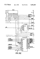
- FIG. 3 shows a schematic representation of the back-plane bus of the concentrator 10.
- Each of the generic channels 112, 114, and 116 are connected to a plurality of LAN management cards or management modules 118, media distribution cards or modules 120, and bridging and routing modules 122 and 124 for communication between channels (and between networks of different protocols). Also configured in the network architecture are plural power supply power modules 126 and a control module 128.
- Generic channels 112, 114 and 116 or LAN Channel A,B,C provide a generic multichannel backplane.
- the media distribution modules 120 are LAN media connection cards that implement a particular protocol.
- the modules 120 include ports 119 for connection to a specific medium 121.
- the bridging and routing modules 122, 124 are store-and-forward devices that either convert one protocol to another, filter (receives all transmissions from one port, and selectively transmits to another port), or both.
- the control card 128 implements a central system function of the LAN system according to the invention.
- the LAN management cards 118 are Network Management cards that integrate the function of prior art hub management cards and LAN-specific management cards.
- the backplane bus generally designated 100 consists of 96 lines (common wires). Of these 96 lines, 42 of them are allocated to a common channel used for global maintenance functions and power distribution. The remaining 54 lines are logically divided into three generic channels of 18 lines each. Each of these channels provides all the functionality of a single backplane bus as implemented in the prior art.
- the channels 112, 114 and 116 are not dedicated to a particular access method, packet format or data rate; rather, they are provided to the users as generic data channels. Each channel 112, 114 and 116 may be used to provide a single protocol; the assignment of the protocol to one of the channels 112, 114 and 116 may be changed arbitrarily at any time (presuming agreement among all users of the channel).
- Table 1 shows a table of pin assignments of a specific implementation of the generic multichannel architecture on the concentrator backplane according to the invention.
- the slots of the concentrator 10 (for example 17 slots receiving 17 different modules) are provided such that each slot connects a module to the entire backplane bus or in the preferred embodiment to each of the 96 lines.
- Table 1 shows the definition of each of the 96 lines. As can be seen from Table 1, lines 13 through 29 provide channel #1 or channel A. Lines 54 through 61 and 86 through 93 provide what is listed as channel #2 or channel B whereas line 67 through 84 provide channel 0 or C.
- the remaining lines are used to provide common service to all modules. These are power and grounds, central management channel, unique slot identifications (Slot-ID), and various system clocks. Some are high speed signals implemented in Bus Transceiver Logic, (BTL), technology logic levels and some are DC or slow speed signals implemented in CMOS compatible logic levels. These signals do not provide any specific function of a LAN implementation but provide services for the concentrator and its management.
- BTL Bus Transceiver Logic
- BNMMACT* Management module present signal
- BMONADD* port address (5 MSB's- slot address, 4 LSB's -port #, all open collector)
- BNMMSI* serial transmit line (open collector on ALL modules except NMM
- BNMMSO* serial transmit line (open collector on NMM)
- BCLK20 20 MHz clock from ControlCard
- BCLK8 8 MHz clock from ControlCard
- BCLK10 10 MHz clock from ControlCard
- BCLK10* 10 MHz clock (inverted) from ControlCard
- Extended Module edge connector pin that is an MFBL type pin (Make Rist, Break Last)
- Each of the users of the backplane bus may elect to transfer data on one or more of the channels 112, 114 and 116 simultaneously. Users offering multiple external interfaces (each providing a particular corresponding protocol) may logically assign these interfaces to any channel, without restrictions on combinations.
- Module Channel Switching users can create a logical network configuration independent of physical network placements.
- Module switching is made possible by the generic multichannel architecture. Module switching is accomplished by controlling connections from circuits that control a particular protocol to a particular channel. For example, an EthernetTM type module is connected to a particular backplane channel by its local collision detection and data handing circuits. Although only one path to a channel is active, paths to all the channels to be used need to be present to accomplish the module switching.
- FIG. 4 is a module switching schematic which shows an encoded signal representing the selected active channel. Four possible combinations of the signal can be selected for the generic channels A, B, C, or for the isolated mode. All the other signals represent specific implementation of EthernetTM protocol on a generic channel.
- Input signals BID ⁇ 4:0> represent the Slot-ID read by the module.
- Input signals ADD ⁇ 1:0> represent the Port-ID generated by the module denoting the active port ID.
- Input signals DDATA and DDATAEN represent the actual data and the data enable, respectively, delayed by one clock cycle.
- the input signal DATAEN represents non-delayed DDATAEN signal.
- the input signal DGT1 represents the condition when more than one port is active. This denotes the sole collision condition when a module is in isolated mode and acts as an independent and isolated LAN.
- the input signals LCOL and RCOL represent local collision and remote collision conditions, respectively.
- the output signals BxMONADD ⁇ 8:0>, BxDATA, BxDATAEN, BxLCOL, and BxRCOL, where ⁇ x ⁇ represents the number of channels, are signals driven onto the backplane with BTL logic levels.
- the source for these outputs are common to all.
- ENCHNLBO-1 By the means provided by the following signals ENCHNLBO-1, only the selected channel is activated.
- the input signals ENCHNLB ⁇ 1:0> represent the selected channel (one of Channel 0, 1,2 or Isolated) in binary encoded form.
- the decoder U66 translates these encoded signals to generate ENCHNLO-3 and ENISOLATE output signals. These output signals enable respective channels for LAN communications.
- the modules switch channels by controlling the connections to each channel through these signals.
- Output signals to the backplane are routed by the way of enabling the drivers. All respective inputs from the backplane are connected together through tri-state outputs, effectively multiplexing inputs from the active channel only.
- FIG. 5 shows a programmable logic device U47 and a logic circuit for a particular protocol, EthernetTM, that switches modules to any channels.
- the input signals STBOUT ⁇ 03:00> and LDOUT ⁇ 03:00> are data enable signals and data output signals, respectively, and represent LAN data from ports. In this case, there are four sets of signals for a four port implementation.
- the input signals MONADD ⁇ 8:4> represent the active module Slot-ID and the input signals BID ⁇ 4:0> represent the module Slot-ID. They are compared by U11 which produces an output (pin 19) that is active when they differ. This is the means for detecting collision using Slot-ID.
- U47 When more than one port is active at the same time, U47 generates the output signal GT1 which forces the output of the U11 to become active. When the output of the U11 becomes active, a collision is detected.
- the output LCOL is generated from U69 which is delayed by one clock cycle.
- the signals COLOUT ⁇ 03:00> are all logically ORed together to produce RCOL, which is delayed through U69.
- the RCOL signal when it is asserted, represents a remote collision that occurred elsewhere and is received by a single port.
- the outputs ADD ⁇ 1:0> are generated by U47 which denote the active Port-ID.
- the outputs DSTBOUT ⁇ 03:00> are generated from U69 which delays the inputs STBOUT ⁇ 03-00>.
- a DATAEN signal is generated when any of the STBOUTs is active.
- This logic device U47 also "OR's" together the LDOUTs to generate the DATA signal going to the backplane. In addition, this logic device generates that the signal port 1 ID is invalid.
- Table 2 below shows the module switching for the programmable array logic implementation of the EthernetTM portion of the system.
- Table 3 lists the test vectors for the programmable array discussed with reference to Table 2 and FIG. 5.
- a multichannel backplane bus allows multiple protocols to share a common backplane bus, and allows multiple data packets to share the bus at any given time.
- a generic data channel allows complete flexibility for growth and change. At any time the protocol for a channel may be redefined. As new protocols are developed, a method of supporting the new protocols on the generic data channel can be designed and included. Costly protocol converters are not required.
- An isolated data channel allows complete independence for isolating any of the modules from the backplane and to continue to operate, simultaneously with the backplane operation.
- FIG. 6 represents the per-channel logic of channel 1 to explain the per-port switching functions.
- the per-channel logic for Channels 0, 2 and Isolated can be constructed by replacing CH1 with CH0, CH2, or CHISO.
- Each input STBOUTxx is qualified by the channel selection signal ENxx CHyy port.
- the signal STBOUTO qualified by the signal ENO CHI signifies that if the port 0 is configured for the channel 1, the output of the logical AND function through 74AS08 will be active.
- COLOUT ⁇ 03-00> are modified from FIG. 5 to qualify each input for Channel 1 applicability. Except for the notation change, the signals provide the same functions as description of FIG. 5.
- FIG. 6 describes per channel logic of a particular protocol, EthernetTM, switching ports from one channel to another.
- EN0 -- CH1, EN1 -- CH1, . . ENxx -- CHyy represent control signals that enable a particular port, xx, for each channel logic yy.
- Each module employs a set of bus drivers/receivers per channel, or one set of drivers and electric and/or mechanical switches to all channels. By enabling one of the sets of drivers, or enabling a set of switches to a channel, a module is connected and functional on that particular channel.
- the module switching to any channel can be controlled by hardware switches, or software control, or both.
- each module is configured to operate on that particular channel.
- Each module has hardware switches that initialize the channel selection.
- the software system can confirm or override that selection.
- the modular switching arrangement according to the invention allows:
- Each Physical Port Switching to any Channel allows users to connect to a LAN system without any restrictions.
- Each port is allowed to be configured to any logical channel present in the LAN system.
- Port switching to any channel is accomplished by duplicating the circuits, which control a particular protocol, the same number of times as there are channels (See FIG. 7).
- FIG. 7 describes the backplane interface for per-port switching function.
- each channel has an independent set of input signals produced by respective per-channel logic described in FIG. 6.
- the suffix ⁇ CH1 ⁇ , ⁇ CH2 ⁇ etc. are used to distinguish one set of input signals from the others (compared to FIG. 4).
- the means of enabling and disabling each channel is provided by the signals ENCHNL ⁇ 2:0> and ENISOLATE to save power from inactive connections.
- Each protocol circuit owns a path to its own channel. An additional switching function must be performed from a media port to the protocol circuits.
- each media port can be configured to switch from one channel to another.
- a forth protocol circuit is provided to connect ports that are isolated from the backplane. In principal, the number of protocol circuits for isolated ports is not limited.
- each port can be configured to operate on a particular channel, or to be isolated.
- FIG. 7 shows a port switching circuit schematic where each channel dependent logic has a suffix of -- CHnn, and where nnn represents the channel identification.
- the physical port channel switching feature of the invention allows:
- FIG. 8 shows the hub management architecture according to the invention, and the management entities present in the system according to the invention.
- LAN MGMT 181 is the protocol dependent aspect of the network management associated with the LAN management module 118.
- Agent 182 is the network management entity that controls and reports management status too other agents.
- CARD CTRL module control
- HUB MGR designated 184 is the protocol independent LAN system management.
- the only modules capable of managing the hub are Network Management Modules (NMMs)118, although in principle any module can be made to have the hub master capability.
- NMMs Network Management Modules
- the election algorithm is not limited by the current configuration, i.e. there is not limit to the number or type of potential candidates.
- SCI Master-- a module which has its Tx line tied to pin 50 of the Hub backplane (BNMMSO--) and its Rx line tied to pin 49 of the Hub backplane (BNMMSI--).
- An SCI master is not necessarily the Hub Master.
- SCI Slave--a module which has its Tx line tied to pin 49 of the Hub backplane (BNMMSI--) and its Rx line tied to pin 50 of the Hub backplane (BNMMSO--).
- Hub Master--a module that is an SCI Master and that initiates SCI communications.
- the minimum length of an SCI packet is one byte, which is simply an address character.
- a module must meet the following hardware requirements for it to be configured as a Hub Master.
- Modules that can be hub masters have three basic SCI states that they can be in (and a fourth undefined state). These SCI states are listed in Table 4 below.
- time-out values for the slave state and the election state are specified below.
- a summary of the actions taken in different states is listed in table 5.
- the NMMs default to SCI master mode and the control card is in SCI slave mode (the control card is always an SCI slave).
- HubMasterID There is a variable on the control card called HubMasterID, which comes up as -1 indicating that there is currently no Hub master. If the BNMMACT signal is not asserted, the control card assumes that there is no module that wants to be Hub Master, and no election takes place.
- the control card begins the election by issuing a BREAK on its Tx line (BNMMSI--). The interpretation of the BREAK character is explained later. It then goes through every slot, except its own slot, issuing a one byte SCI packet (the slot address). If it does not receive an ACK, it tries the next slot. If it receives an ACK, it sets the slot number in the HubMasterID variable, it sends a one byte SCI packet (address FF[hex]) which tells all other candidates to immediately toggle to SCI slave mode, and it stops initiating any SCI communications. It then answers any inquiries from the hub master and monitors the SCI for activity.
- control card If no sleeping pills are received by the control card for a given time (specified below), the control card assumes that the hub master has failed, and initiates another election. The control card does NOT verify that any SCI communications were initiated by or from the hub master's slot. The hub master can maintain activity on the SCI by periodically issuing sleeping pills as described above.
- a module If a module wishes to be the hub master but another module was elected, it can force the current hub master to resign by sending a BREAK character while it is in SCI slave mode.
- a module acting as the hub master receives a BREAK, it immediately stops acting as the hub master (i.e. stops initiating SCI communications) and it issues a BREAK character. This will cause all other potential hub masters to toggle to SCI master mode. The lack of SCI activity will cause the control card to time-out and start another election.
- other NMMs see a BREAK character while they are configured as SCI slaves, they must toggle to SCI masters and go through a re-election.
- a BREAK sent by the Hub Master indicates that it is resigning.
- NMMs There is a priority variable on the NMMs which can be set to a value between 0 and 255. This number is defined as the number of election polls to ignore before answering an election poll. The number is decremented after each poll until the value reaches zero or until the election ends. The exception to this is the value 255, which is used to indicate that the module should never answer an election. If this value is the priority, then it is never decremented.
- the default value for priority after power-up reset is 255, so the management agent must change this value in order for a hub master to be elected.
- the priority can be used to ensure, for example, that a desired module is always elected after a power failure.
- control card will send SCI packets until one is ACKed.
- the management method according to the invention allows:
- EthernetTM HUB vendors employ analog collision detection on their backplane, similar to that of 10Base5 or 10Base2, where either current or voltage is summed to represent number of simultaneous transmissions. A voltage or current level that represents two or more simultaneous transmissions is deemed to be a collision.
- the number of bits for the slot-ID is set to 5.
- the Bus Transceiver Logic, BTL technology chosen for the generic multichannel architecture system according to the invention meets the hardware requirement.
- Each slot of a backplane has hardwired a unique binary-coded slot-ID numbered from 0 to 16.
- the collision enforcement signal is assigned a common backplane pin per channel, and is known as a Local Collision.
- a backplane collision detection method using slot-ID allows parallel bit-comparison with collision enforcement signalling to ensure collision detection on a backplane.
- N represents the number of slots on a backplane
- M represents the number of uniquely assigned bits of slot-ID which are needed to perform this collision detection
- M is defined as the smallest integer that satisfies N ⁇ 2 M .
- this unique slot-ID is read by each active module and compared to its own.
- Backplane circuits for the slot-ID allow multiple bus drivers on a single line. If multiple slot-IDs are driven onto the backplane, a slot-ID on the backplane will not match at least one of the active module's slot-ID. If the read slot-ID is the same as its own, the module does nothing more. If the read slot-ID is different than its own, then the module asserts a collision-enforcement signal. The collision enforcement signal is held active as long as the slot-ID read does not compare with its own slot-ID. All modules monitor this collision enforcement line to detect collisions.
- FIG. 5 also shows the collision detection logic system according to the invention.
- the signals BID ⁇ 4:0> are a uniquely encoded Slot-ID signal per module such that the slot 0 of the concentrator has the binary encoding of 00000 and the slot 15 of the concentrator has the encoding of 01111.
- the signals MONADD ⁇ 8:4> represent the portion of the active module address that corresponds to the Slot-ID. When a module is active, the Slot-ID is enabled onto the backplane via BxMONADD ⁇ 8:4> signals, where x represents the channel number.
- the signals MONADD ⁇ 8:4> represent the BxMONADD ⁇ 8:4> read by the BTL receiver.
- the signals MONADD ⁇ 8:4> are compared to BID ⁇ 4:0> if and only if the module is active in sending data onto the backplane.
- the hardware requirement for the embodiment of this invention is that the logic family used for asserting the slot-ID, Data, Data Enable, and other support signals be capable of supporting simultaneous assertion of these signals by multiple drivers.
- the collision detection scheme of the invention allows:
- FIG. 9 shows another collision counting logic schematic which describes how MONADD ⁇ 8:0> is latched to be used as a vector into a memory address base for collision.
- the input signal LCOLCNT enables the data latches in U33 and U57 to trap the MONADD ⁇ 8:0> to be used later by the collision counting circuit, described in FIG. 10.
- the output signals EADDR ⁇ 18:1> along with signals ER, EUDS, and ELDS represent signals that interface the monitor address to the address bus of the Ethernet Controller IC, U24, in FIG. 16.
- FIG. 9 is still another collision counting logic schematic which describes how serial bit streams of EthernetTM are counted, and how collision is qualified.
- the devices U75 and U81 represent the Programmable Logic Devices (PLD) described in FIG. 13 and 14 respectively as finite state machines. Outputs from U75 control U80, an 8 bit counter, to count a specific number of bits being received for the state machines to determine a correct cut-off point for remote collision counting per port.
- the signals EDAL ⁇ 15:0> represent a data bus connection made to U71 and U63, both of which are loadable 8 bit counters.
- the counters are under the state machine control and their function is to read the contents of the data bus, increment by one, and write the result onto the data bus. This circuit is used to count remote collision per port and the local collision.
- FIGS. 13 and 14 describe the functions of programmable logic devices U75 and U81.
- Precise Collision Counting per-Port on every activity detected, the length of the network activity is counted. The counting starts when SFD is detected or when a double zero is detected. Any activity that is less than or equal to 51.1 micro Seconds (equivalent to 511 bits) is considered as a collision, and its source module Slot-ID and port ID is recorded. If local collision has been detected through the collision enforcement signal, as described above, the recorded IDs are discarded, and the local collision statistics are updated. If local collision has not been detected during the entire transmission, and the transmission length was less than or equal to 51.1 ⁇ Sec, the collision statistics of that particular module and port is updated using the Slot-ID and Port-ID.
- the initial implementation of this aspect of the invention is in dedicated digital hardware.
- a block of RAM is assigned for recording the collision statistics of each port of each of the modules, and one location of RAM is assigned for local collision statistics.
- FIG. 11 is a further collision counting logic schematic which describes how collision is detected, when the local EthernetTM controller is transmitting.
- FIG. 11 represents the Ethernet Interface logic that has identical function as FIG. 5, but is implemented for a single port device as in the Management module where one Ethernet Controller IC resides.
- the signal ETENA is analogous to STBOUTnn in FIG. 5 and represents data enable
- LANCETX is analogous LDOUT in FIG. 5 and represents data.
- FIG. 12 is a still further collision counting logic schematic which contains the PLD U11 that implements a part of the state machine described in FIGS. 13 and 14.
- the programmable logic device U11 among other independent functions, provides the decoder function to translate ENCHNLB ⁇ 1:0> to ENCHNL ⁇ 2:0>.
- the signal ERENA represents the receive data enable and is used in this circuit with U5, an 8 bit counter, to provide a measurement of the receive duration to be used by the finite state machine in FIG. 14.
- FIG. 13 shows a collision detection logic state machine.
- This finite state machine, FSM describes how packet length counting is started and how the collision fragment is qualified with the resulting length.
- the Slot-ID and port-ID are used as a vector into the block of RAM assigned for recording collision statistics, for fetching a count to be updated.
- a dedicated counter and a set of finite state machine increments the contents and then writes it back to the same location fetched.
- a pre-determined location containing the local collision count is updated by the same circuit.
- FIG. 14 shows another collision detection logic state machine which describes how a long word (32 bit) counter is maintained using 16 bit counters per Port-ID and Slot-ID signals.
- FIG. 15 shows EthernetTM statistics counting logic and how the EthernetTM controller receives buffer memory addresses latched at a proper qualified moment, and how MONADD ⁇ 8:0> is latched for eventual writing to the memory location.
- the input signal, GETADD enables the data latches in U72 and U64 to trap the MONADD ⁇ 8:0> signals to be used later to "stamp" each received data packet with the value of the MONADD, which represents the Port and Slot-ID.
- the contents of the MONAFF ⁇ 8:0> are used as data.
- the outputs from these latches are connected to the data bus, EDAL ⁇ 8:0>, for this purpose.
- the control of this operation is described in the state diagram in FIG. 17.
- the signals EADDR ⁇ 18:6 > represent the address bus of the Ethernet Controller interface.
- the latches U45 and U36 store the particular address of the packet buffer to be used later as an address for the "stamping of the data packet. The control of this operation is also described in the state diagram in FIG. 17.
- the precision collision counting per-port aspect of the invention provides:
- a dedicated digital circuit monitors the bus activity of EthernetTM controller IC. During the monitoring, the receive buffer memory location that an EthernetTM controller uses, is recorded. Once the count has expired, slot and port IDs are written into the reserved location of the particular received buffer in use.
- FIG. 16 shows the EthernetTM statistics counting logic schematic, the EthernetTM controller interface and the programmable device that implements the FSM shown in FIG. 17.
- the representation of the Ethernet Controller interface in this figure is quite standard and is included to provide clarity.
- the device U39 and its input makes the FIG. 17 state diagram description easier.
- EDAL ⁇ 15:0> represents multiplexed address and data
- EADRR ⁇ 18:0> represents an address bus
- UADDR1 represents a single address signal from the host for slave random access to the Ethernet Controller
- EDTACK represents an input for the data ready signal
- ER represents an input/output for read or write
- EDAS represents an input/output for data strobe
- EAS represents an output for address strobe to access memory mapped devices
- EIRQ represents an output for interrupt request to the host
- ECS represents an input for slave access from the host
- EUDTACK represents an output for slave access from the host
- ERXD represents received data
- ECLSN represents local collision
- ERENA represents receive enable
- CNT256 represents the length of ERENA longer than 256 bit times (where bit time is 100 nano-seconds) and then 512 bit times, or every 256 bit times thereafter, and is generated in FIG. 12.
- the EthernetTM controller from Advanced Micro Devices (AMD) is used.
- Each receive buffer has a 16 bit word location reserved for the slot and port ID, and each receive buffer starts on a 32-byte boundary to allow an all zero vector to point to the reserved location to write the slot and port ID. If activity is detected, and if the EthernetTM controller does not provide a direct memory access (DMA) of the received packet to the receive buffer, the dedicated logic does not write the port or slot IDs.
- DMA direct memory access
- a dedicated logic monitors and counts received network activity. If it exceeds 256 bits beyond the preamble, it knows that the memory transfer the EthernetTM controller makes is to the current buffer, because the AMD controller uses a 32 byte (256 bit) FIFO (First In First Out) scheme to buffer incoming packets. The AMD controller must empty the contents of the FIFO before it overflows. The monitoring logic uses this indication to latch the memory address and writes the port and slot ID's to associate the origin of a particular received packet with the packet itself.
- FIFO First In First Out
- the monitoring logic allows:
- An EthernetTM, or CSMA/CD channel is made possible by synchronizing bit streams of EthernetTM packets to a central clock, common to all modules connected to the same channel. This is accomplished by a First In First Out (FIFO) system that receives data at one frequency, and transmits at the frequency common to all modules.
- FIFO First In First Out
- the synchronous channel allows:
- the device of the invention to provide a system with no bit losses once and EthernetTM packet enters into a synchronous EthernetTM channel.
- FIG. 17 shows the EthernetTM statistics counting logic finite state machine (FSM).
- the FSM performs master and slave bus arbitration, slave access from a host, and qualification of a receive buffer memory address latch pulse through counting of packet length. For this particular implementation, integration of the above functions makes the logic simpler.
- Table 6 The input/output conditions for transferring from one state to another is described Table 6 shown below:
- FIG. 18 is a half-repeater logic showing programmable logic devices that implement the logic shown in Table 7 FSM.
- the programmable logic devices represented in FIG. 18 implements the finite state machines described in Table 7.
- the references to U10, U5 and U16 in Table 7 correspond to the devices in this figure.
- All three devices U10, U5 and U16 function in synchrony to perform the function of properly formatting the data packet originating from the Ethernet Repeater IC, U39 in FIG. 19, and transmitting to the backplane through the circuits described in FIG. 4 or FIG. 7, depending on module or per-port switching option.
- the devices also detect data from the backplane when it is not transmitting to the backplane and transmit data from the backplane to each of the ports on the module without loss of any preamble bits and without any variation in delay from the backplane to the port.
- the signal TENN represents data enable from the Ethernet Repeater IC.
- the signal MTXD represents data associated with TENN from the same IC.
- the signals CLDATA and CLDATAEN represent, clocked data coded using Manchester Coding, and associated data enables to be transmitted to the ports.
- the signal RXDATAENA represents the data enable received from the backplane.
- Table 7 shows the internal logic definition of U5, U10, U16, all programmable logic devices.
- the syntax used is of ABELTM, a logic compiler from the Data I/O Corporation.
- the FSMs implement data transfer functions as described to and from the backplane, and work in conjunction with a standard IEEE 802.3 repeater, and their particular actions are as specified in the standard.
- Half-repeater implementations of EthernetTM Modules according to the invention allow more 802.3 repeaters in cascade in conjunction with the EthernetTM network channel.
- an EthernetTM media port is connected to a repeater that is connected to a EthernetTM network channel
- any activity arriving at the input of the media port has a preamble loss.
- the repeater regenerates the lost preambles and sends the data out to the backplane.
- the EthernetTM channel then carries the data without any preamble loss and without delay variability, because the EthernetTM channel requires all signals to be synchronous to the master clock of a hub. Delay of data from the first bit to the last is fixed.
- Multiple repeaters may be used to act as a single repeater, and offers approximately one half the IEEE 802.3 repeater limitations.
- FIG. 19 describes one implementation of this half-repeater logic invention using 10BaseT, Ethernet on twisted pair media, repeater IC, U39.
- This drawing does not describe unique aspects of the half-repeater invention but is included to add clarity and provide the interconnection between an Ethernet Repeater IC and the stae diagrams in Table 7 and FIG. 18.
- the token ring improvement of the invention includes means for establishing a logical ring by the use of a Slot-Id scheme.
- the requirements are that each slot be coded with a unique Slot-ID, and the number of slots be equal to or less than the number of available lines assigned to the token ring.
- Each token ring module in a hub recognizes the Slot-ID, and transmits a repeated token ring signal onto the line corresponding to its Slot-ID, and listens to all other lines. To establish a logical ring, each module will pick a unique and active module from which to receive. Although many algorithms based on a unique Slot-ID scheme that meets such a requirement may be employed, one algorithm is preferred.
- each module picks the closest active neighbor with the largest Slot-ID less than its own from which to receive. If no such neighbor exists, it picks the active neighbor with the largest Slot-ID greater than or equal to its own.
- the 17 squelch outputs and the 17 transmit select lines drive the backplane ring control element, which uses these lines to determine which of the 17 backplane lines to receive its data from. As with the transmit decoder, this function can be overridden by network management.
- the operation of this element is basically as follows:
- the algorithm according to the invention uses the following steps:
- RXON(1) to RXON(n-1) are active, set RXSEL to the "highest" line which has RXON(i) active (i.e., N-1, N-2, etc. in order of preference).
- RXON(1) to RXON(N-1) If none of RXON(1) to RXON(N-1) is active, set RXSEL to the highest line of RSEL which is active.
- This algorithm should rum continuously to build and maintain the ring, even if cards are removed from or added to the hub.
- the implementation can use a static array of logic to generate the RXSEL(i) with the following equations: ##EQU1## where the equation wraps line 17 to line 0 when TXON(17) is reached, and ends with a term which contains TXSEL(i) and all RXON signals except RXON(i) are inactive.
- Each token ring module in a hub recognizes the Slot-ID, and transmits a repeated token ring signal to the line corresponding to its Slot-ID, and listens to all other lines.
- each module will pick a unique and active module with the same data rates from which to receive. Thus each module detects activity, and data rate at both 4 Mega Bits/Sec and 16 Mega Bits/Sec. Allowing for jitter build-up, and implementational margins, 4 Mega Bits/Sec token ring cannot present a data edge any faster than 125 nSec nor slower than 1000 nSec.
- 16 Mega Bits/Sec token ring cannot present a data edge any faster than 31.25 nSec nor slower than 250 nSec.
- frequency discriminator between 31.25 to 125 nSec, or 250 nSec to 1000 nSec, with proper allowances for jitter and engineering tolerances, the data rate can be positively detected.
- the ring is established in exactly the same manner as the above described Ring Establishment using Slot-ID, with the exception that the data rate is compared each time the presence of token ring activity is tested. If the data rate is different, the activity, if detected, is ignored.
- a single data rate detector is employed to indicate 4 megaBPS versus 16 megaBPS.
- the data rate is detected by a edge-triggered retriggerable mono-stable multi-vibrator (one-shot), connected to a token ring data line on the backplane.
- the pulse width, or the time constant, is set to be nominally 50 Nano-Seconds +/-10%.
- a second circuit a digital sampling circuit with a sampling period of 50 nSec, counts the duration of the output from the one-shot.
- any contiguous output of 800 nSec (allowing for margins, where the minimum sized frame is an abort sequence of two octets or 1000 ns) or more is detected, data rate for that token ring line is deemed to be 16 Mega Bits Per Second, otherwise, 4 Mega Bits Per Second.
- a means of establishing multiple logical rings on a backplane by the use of configuration management is another feature of the invention.
- the requirements are that each slot be coded with a unique Slot-ID, such that configuration management entities may individually address each module.
- each module can be configured to receive from a particular line. Although not a requirement, each module always transmits to a line corresponding to its own slot-ID, because additional freedom of assigning transmit lines to any arbitrary backplane line complicates logic implementations without added benefit. Each module reports its own data rate to the management function. The management then controls interconnection of each module to another. Via this configuration, control any number of rings can be established, only limited by the number of modules and the backplane communication line. This allows multiple logical Token Rings on a backplane through the configuration management.
- Software or Hardware Control of the configuration is provided for the purpose of creating the Multiple Ring establishment. This allows multiple logical rings of compatible speeds of 4 MegaBPS and 16 MegaBPS on a backplane through the configuration management.
- FDDI of 125 megabaud, or 100 megaBPS is signaled on a set of five data lines in parallel. Before any data transmission is allowed, each FDDI module establishes the ring by contending for an inactive set of data lines. The sets of data lines are predetermined, and its logical order is established.
- a module monitors activity on all sets of data lines, it does not contend for any set of data lines. If a module detects an inactive set of data lines while seeking from the lowest order to the highest order of sets, it enables its own Slot-ID onto the set of data lines. For an arbitrarily long duration denoted as TC, the set of data lines are monitored and compared with its own Slot-ID. If there is no discrepancy during this time, the module transmits to the set of data lines which it now owns. If there is a discrepancy, the module waits for the duration equalling the Slot-ID times TC. Then it reverts back to listening to a set of data lines for activity.
- a module Once a module owns a set of data lines, it immediately starts sending IDLE, and starts the Ring Establishment process. Ring is established in the same way as the above in Token Ring establishment. To establish a logical ring, each module will pick a unique and active module from which to receive.
- Each module picks the closest active neighbor with the highest order less than its own from which to receive. If no such neighbor exists, it picks the active neighbor with the highest Slot-ID greater than or equal to its own.
- a set of data lines are provided to signal a 125 megabaud signal.
- the preferred implementation provides five data lines per set, and three sets per channel.
- Slot-ID is used to detect contention of data lines and Slot-ID is used to provide a unique non-overlapping waiting period.
- This invention allows an FDDI (Fiber Data Distribution Interface protocol) ring to be established by using a unique Slot-ID scheme to resolve multiple FDDI modules contending for the same set of data lines.
- FDDI Fiber Data Distribution Interface protocol
- Each slot be coded with a unique Slot-ID, such that configuration management entities may individually address each module to configured modules.
- a Token Bus channel To implement the Token Bus protocol, a Token Bus channel must provided a means of detecting data corruption and a means for broadcasting data transmissions to all the other end-nodes. Both of these are common with the EthernetTM network protocol. If a bigger FIFO scheme is provided to service frequency mismatch of the increased packet size of 32 Kbytes of Token Bus, compared to the 1.5 Kbytes of EthernetTM, and an additional data line is provided to carry non-data symbols, the same EthernetTM module backplane interface with these modifications, can carry the Token Bus protocol.
- the collision or in this case data corruption, is detected and enforced by detecting two or more simultaneous transmissions. Collision is detected in the same way as the above-described Collision Detection using Slot-ID.
- all data transmissions from any port are broadcast to all other ports, except during a collision. During a collision, all data transmissions from any port are broadcast to all the ports.
- the implementation of the Token Bus needs one additional data line to provide non-data symbols in addition to the binary zero and binary one.
- the FIFO depth is increased from 4 bits to 52 bits to accommodate the frequency mismatch of packet length of up to 32 kilobytes, as allowed in the IEEE 802.4 Token Bus standard.
Landscapes
- Engineering & Computer Science (AREA)
- Computer Security & Cryptography (AREA)
- Computer Networks & Wireless Communication (AREA)
- Signal Processing (AREA)
- Small-Scale Networks (AREA)
- Accessory Devices And Overall Control Thereof (AREA)
- Computer And Data Communications (AREA)
- Facsimiles In General (AREA)
Priority Applications (7)
| Application Number | Priority Date | Filing Date | Title |
|---|---|---|---|
| US07/687,590 US5301303A (en) | 1990-04-23 | 1991-04-16 | Communication system concentrator configurable to different access methods |
| CA002079671A CA2079671A1 (en) | 1990-04-23 | 1991-04-22 | Multichannel backplane bus system architecture |
| PCT/US1991/002802 WO1991016679A1 (en) | 1990-04-23 | 1991-04-22 | Multichannel backplane bus system architecture |
| EP91909610A EP0526580A1 (de) | 1990-04-23 | 1991-04-22 | Mehrfachkanal-erdbussystemarchitektur |
| JP91509008A JPH05506553A (ja) | 1990-04-23 | 1991-04-22 | 多チャネルバックプレーンバスシステムアーキテクチャ |
| IL9877191A IL98771A (en) | 1991-04-16 | 1991-07-09 | Multi-channel backplane connection strip system architecture |
| US08/221,383 US5530842A (en) | 1990-04-23 | 1994-03-31 | Generic backplane system which is configurable to serve different network access methods simultaneously |
Applications Claiming Priority (2)
| Application Number | Priority Date | Filing Date | Title |
|---|---|---|---|
| US51284990A | 1990-04-23 | 1990-04-23 | |
| US07/687,590 US5301303A (en) | 1990-04-23 | 1991-04-16 | Communication system concentrator configurable to different access methods |
Related Parent Applications (1)
| Application Number | Title | Priority Date | Filing Date |
|---|---|---|---|
| US51284990A Continuation-In-Part | 1990-04-23 | 1990-04-23 |
Related Child Applications (1)
| Application Number | Title | Priority Date | Filing Date |
|---|---|---|---|
| US08/221,383 Continuation US5530842A (en) | 1990-04-23 | 1994-03-31 | Generic backplane system which is configurable to serve different network access methods simultaneously |
Publications (1)
| Publication Number | Publication Date |
|---|---|
| US5301303A true US5301303A (en) | 1994-04-05 |
Family
ID=27057683
Family Applications (2)
| Application Number | Title | Priority Date | Filing Date |
|---|---|---|---|
| US07/687,590 Expired - Lifetime US5301303A (en) | 1990-04-23 | 1991-04-16 | Communication system concentrator configurable to different access methods |
| US08/221,383 Expired - Lifetime US5530842A (en) | 1990-04-23 | 1994-03-31 | Generic backplane system which is configurable to serve different network access methods simultaneously |
Family Applications After (1)
| Application Number | Title | Priority Date | Filing Date |
|---|---|---|---|
| US08/221,383 Expired - Lifetime US5530842A (en) | 1990-04-23 | 1994-03-31 | Generic backplane system which is configurable to serve different network access methods simultaneously |
Country Status (5)
| Country | Link |
|---|---|
| US (2) | US5301303A (de) |
| EP (1) | EP0526580A1 (de) |
| JP (1) | JPH05506553A (de) |
| CA (1) | CA2079671A1 (de) |
| WO (1) | WO1991016679A1 (de) |
Cited By (84)
| Publication number | Priority date | Publication date | Assignee | Title |
|---|---|---|---|---|
| US5420986A (en) * | 1992-07-30 | 1995-05-30 | Digital Equipment Corporation | FDDI concentrator with backplane port for dual datapath systems |
| US5432907A (en) * | 1992-05-12 | 1995-07-11 | Network Resources Corporation | Network hub with integrated bridge |
| US5432789A (en) * | 1994-05-03 | 1995-07-11 | Synoptics Communications, Inc. | Use of a single central transmit and receive mechanism for automatic topology determination of multiple networks |
| US5442628A (en) * | 1993-11-15 | 1995-08-15 | Motorola, Inc. | Local area network data processing system containing a quad elastic buffer and layer management (ELM) integrated circuit and method of switching |
| US5442750A (en) * | 1991-10-04 | 1995-08-15 | Wellfleet Communications | System for transmitting data between systems using selected subsets of plural interconnecting bus lines and including selection of a compatible transmission speed |
| US5485455A (en) * | 1994-01-28 | 1996-01-16 | Cabletron Systems, Inc. | Network having secure fast packet switching and guaranteed quality of service |
| US5485576A (en) * | 1994-01-28 | 1996-01-16 | Fee; Brendan | Chassis fault tolerant system management bus architecture for a networking |
| US5497460A (en) * | 1994-06-20 | 1996-03-05 | International Business Machines Corporation | System and method for determining network connectivity |
| US5509123A (en) * | 1994-03-22 | 1996-04-16 | Cabletron Systems, Inc. | Distributed autonomous object architectures for network layer routing |
| US5522042A (en) * | 1994-01-28 | 1996-05-28 | Cabletron Systems, Inc. | Distributed chassis agent for distributed network management |
| US5524254A (en) * | 1992-01-10 | 1996-06-04 | Digital Equipment Corporation | Scheme for interlocking line card to an address recognition engine to support plurality of routing and bridging protocols by using network information look-up database |
| US5526358A (en) * | 1994-08-19 | 1996-06-11 | Peerlogic, Inc. | Node management in scalable distributed computing enviroment |
| US5557745A (en) * | 1990-09-04 | 1996-09-17 | Digital Equipment Corporation | Method for supporting foreign protocols across backbone network by combining and transmitting list of destinations that support second protocol in first and second areas to the third area |
| WO1996038967A1 (en) * | 1995-06-02 | 1996-12-05 | Dsc Communications Corporation | Control message transmission in telecommunications systems |
| WO1996041454A1 (en) * | 1995-06-07 | 1996-12-19 | 3Com Corporation | Backplane architecture for stackable ethernet repeater |
| US5588151A (en) * | 1994-01-31 | 1996-12-24 | Lannet Data Communications Ltd. | Apparatus and method for communication switching including providing information overflow indications |
| US5596723A (en) * | 1994-06-23 | 1997-01-21 | Dell Usa, Lp | Method and apparatus for automatically detecting the available network services in a network system |
| US5613164A (en) * | 1995-03-22 | 1997-03-18 | International Business Machines Corporation | Portable system having data distribution and power distribution removably positioned within portable enclosure during shipping and adapted for repositioning within internal storage space during operation |
| US5630061A (en) * | 1993-04-19 | 1997-05-13 | International Business Machines Corporation | System for enabling first computer to communicate over switched network with second computer located within LAN by using media access control driver in different modes |
| EP0701347A3 (de) * | 1994-09-09 | 1997-05-28 | Standard Microsyst Smc | Rekonfigurierbare Schaltmatrix für ein lokales Netz |
| US5646939A (en) * | 1995-08-08 | 1997-07-08 | International Business Machines Coporation | Method and apparatus for address to port mapping in a token ring network |
| US5648959A (en) * | 1994-07-01 | 1997-07-15 | Digital Equipment Corporation | Inter-module interconnect for simultaneous use with distributed LAN repeaters and stations |
| US5651002A (en) * | 1995-07-12 | 1997-07-22 | 3Com Corporation | Internetworking device with enhanced packet header translation and memory |
| US5659543A (en) * | 1995-02-22 | 1997-08-19 | 3Com Corporation | Communication method and system for aggregates of separate entities using data/management path and mapping path for identifying entities and managing a communication network |
| US5664105A (en) * | 1994-10-04 | 1997-09-02 | Fluke Corporation | Method and apparatus for network analysis |
| US5666359A (en) * | 1995-07-12 | 1997-09-09 | Compaq Computer Corp. | Method and apparatus for displaying port information |
| US5673395A (en) * | 1993-04-19 | 1997-09-30 | Kawakita; Jun | Process for constructing computer network system of tenant intelligent building |
| US5675735A (en) * | 1994-06-29 | 1997-10-07 | Digital Equipment Corporation | Method and apparatus for interconnecting network devices in a networking hub |
| US5680552A (en) * | 1994-09-20 | 1997-10-21 | Lucent Technologies Inc. | Gateway system for interconnecting different data communication networks |
| US5687356A (en) * | 1992-06-22 | 1997-11-11 | International Business Machines Corporation | Hub and interface for isochronous token ring |
| US5696899A (en) * | 1992-11-18 | 1997-12-09 | Canon Kabushiki Kaisha | Method and apparatus for adaptively determining the format of data packets carried on a local area network |
| US5710777A (en) * | 1992-02-07 | 1998-01-20 | Madge Networks Limited | Communication system |
| US5715407A (en) * | 1992-03-06 | 1998-02-03 | Rambus, Inc. | Process and apparatus for collision detection on a parallel bus by monitoring a first line of the bus during even bus cycles for indications of overlapping packets |
| US5720032A (en) * | 1992-05-12 | 1998-02-17 | Compaq Computer Corporation | Network packet switch using shared memory for repeating and bridging packets at media rate |
| US5748633A (en) * | 1995-07-12 | 1998-05-05 | 3Com Corporation | Method and apparatus for the concurrent reception and transmission of packets in a communications internetworking device |
| US5758070A (en) * | 1995-10-06 | 1998-05-26 | Canon Kabushiki Kaisha | System for dynamically determining a network media type of a LAN using frame type identifying value from a configuration table |
| US5761424A (en) * | 1995-12-29 | 1998-06-02 | Symbios, Inc. | Method and apparatus for programmable filtration and generation of information in packetized communication systems |
| US5765027A (en) * | 1994-09-26 | 1998-06-09 | Toshiba American Information Systems, Inc. | Network controller which enables the local processor to have greater access to at least one memory device than the host computer in response to a control signal |
| US5774689A (en) * | 1995-09-22 | 1998-06-30 | Bell Atlantic Network Services, Inc. | Network configuration management system for digital communication networks |
| US5784404A (en) * | 1993-06-24 | 1998-07-21 | National Semiconductor Corporation | Intelligent repeater functionality |
| US5793983A (en) * | 1996-01-22 | 1998-08-11 | International Business Machines Corp. | Input/output channel interface which automatically deallocates failed subchannel and re-segments data block for transmitting over a reassigned subchannel |
| US5796944A (en) * | 1995-07-12 | 1998-08-18 | 3Com Corporation | Apparatus and method for processing data frames in an internetworking device |
| US5796738A (en) * | 1995-03-13 | 1998-08-18 | Compaq Computer Corporation | Multiport repeater with collision detection and jam signal generation |
| US5802580A (en) * | 1994-09-01 | 1998-09-01 | Mcalpine; Gary L. | High performance digital electronic system architecture and memory circuit thereof |
| US5802106A (en) * | 1996-12-06 | 1998-09-01 | Packeteer, Inc. | Method for rapid data rate detection in a packet communication environment without data rate supervision |
| US5812775A (en) * | 1995-07-12 | 1998-09-22 | 3Com Corporation | Method and apparatus for internetworking buffer management |
| US5825774A (en) * | 1995-07-12 | 1998-10-20 | 3Com Corporation | Packet characterization using code vectors |
| EP0751656A3 (de) * | 1995-06-27 | 1998-10-21 | Canon Kabushiki Kaisha | Protokollunabhängige, anpassungsfähige Netzwerkschnittstelle |
| US5836008A (en) * | 1993-12-08 | 1998-11-10 | Goumillou; Daniel | Communications interface for connection between telecommunications equipment and interface modules |
| US5838683A (en) * | 1995-03-13 | 1998-11-17 | Selsius Systems Inc. | Distributed interactive multimedia system architecture |
| US5838918A (en) * | 1993-12-13 | 1998-11-17 | International Business Machines Corporation | Distributing system configuration information from a manager machine to subscribed endpoint machines in a distrubuted computing environment |
| US5872956A (en) * | 1997-04-24 | 1999-02-16 | International Business Machines Corporation | Design methodology for device drivers supporting various operating systems network protocols and adapter hardware |
| US5875210A (en) * | 1993-06-24 | 1999-02-23 | National Semiconductor Corporation | Method and apparatus for repeating data |
| USRE36182E (en) * | 1992-07-07 | 1999-04-06 | Intel Corporation | Apparatus and method for switching ethernet media type |
| US5892772A (en) * | 1997-04-15 | 1999-04-06 | Lockheed Martin Corporation | Spatial reuse by means of dual homing on a ring network |
| US5898668A (en) * | 1996-12-13 | 1999-04-27 | Siemens Information And Communication Networks, Inc. | Method and system for increasing quality of service at or below a threshold cost |
| US5963719A (en) * | 1996-01-22 | 1999-10-05 | Cabletron Systems, Inc. | Two-pin distributed ethernet bus architecture |
| US6026096A (en) * | 1995-07-12 | 2000-02-15 | Nortel Networks Corporation | Automatic speed sensing in a token ring local area network |
| US6035340A (en) * | 1997-03-19 | 2000-03-07 | Nortel Networks Corporation | Method and apparatus for providing a multiple-ring token ring hub expansion |
| US6044407A (en) * | 1992-11-13 | 2000-03-28 | British Telecommunications Public Limited Company | Interface for translating an information message from one protocol to another |
| US6101538A (en) * | 1993-03-26 | 2000-08-08 | British Telecommunications Public Limited Company | Generic managed object model for LAN domain |
| US6148344A (en) * | 1995-10-16 | 2000-11-14 | Nec Corporation | System and method for enabling an IPX driver to accommodate multiple LAN adapters |
| US6185197B1 (en) | 1995-06-02 | 2001-02-06 | Airspan Networks, Inc. | Control message transmission in telecommunications systems |
| US6219409B1 (en) | 1998-02-27 | 2001-04-17 | Sharegate, Inc. | Premises gateway and premises network interfaces for accessing subscriber premises equipment and communication networks using ring suppression |
| US6275864B1 (en) * | 1991-08-13 | 2001-08-14 | Storage Technology Corporation | Matrix switch for a network management system |
| US20010032283A1 (en) * | 1998-10-08 | 2001-10-18 | Altima Communications, Inc. | Methods and circuits for stacking bus architecture |
| US20020013777A1 (en) * | 2000-03-17 | 2002-01-31 | Diener Glendon R. | Communications services provisioning method and apparatus and object programming language for developing provisioning models |
| WO2001080435A3 (en) * | 2000-04-17 | 2002-04-04 | Adaptive Networks Inc | Power line communication network |
| US6393486B1 (en) | 1995-06-23 | 2002-05-21 | Cisco Technology, Inc. | System and method using level three protocol information for network centric problem analysis and topology construction of actual or planned routed network |
| US6449271B1 (en) * | 1997-11-14 | 2002-09-10 | Broadcom Corporation | System for and method of, providing a header and a trailer in data packets |
| USD465216S1 (en) | 2001-06-01 | 2002-11-05 | Lightchip, Inc. | Optical communications device housing portion |
| US20040081196A1 (en) * | 2002-10-29 | 2004-04-29 | Elliott Stephen J. | Protocol independent hub |
| US6883034B1 (en) | 1995-06-23 | 2005-04-19 | Cisco Technology, Inc. | Method of resolving conflicts in access control lists in router by comparing elements in the lists based on subsumption relations |
| US20050213590A1 (en) * | 2004-03-23 | 2005-09-29 | Nokia Corporation | Universal telecommunication node with software-defined exchangeable protocol architecture |
| US7058067B1 (en) | 1995-03-13 | 2006-06-06 | Cisco Technology, Inc. | Distributed interactive multimedia system architecture |
| US20060203747A1 (en) * | 2005-03-11 | 2006-09-14 | Nortel Networks Limited | Network topology systems and methods |
| US20070076394A1 (en) * | 2005-09-30 | 2007-04-05 | Brandt David D | On-machine backplane mounted modular power and data distribution system and method |
| US20070086376A1 (en) * | 2001-12-05 | 2007-04-19 | Adaptix, Inc. | Wireless communication subsystem with a digital interface |
| USRE39879E1 (en) * | 1992-03-06 | 2007-10-09 | Rambus, Inc. | Method of transferring data by transmitting lower order and upper order memory address bits in separate words with respective op codes and start information |
| US7457234B1 (en) | 2003-05-14 | 2008-11-25 | Adtran, Inc. | System and method for protecting communication between a central office and a remote premises |
| US20090122502A1 (en) * | 2007-11-13 | 2009-05-14 | Rockwell Automation Technologies, Inc. | Drive modularity |
| US20100088455A1 (en) * | 2008-10-07 | 2010-04-08 | Hitachi, Ltd. | Storage system provided with a plurality of storage modules |
| US20100238927A1 (en) * | 2001-10-19 | 2010-09-23 | Brocade Communications Systems, Inc. | Method and system for intelligently forwarding multicast packets |
| US8625427B1 (en) | 2009-09-03 | 2014-01-07 | Brocade Communications Systems, Inc. | Multi-path switching with edge-to-edge flow control |
Families Citing this family (61)
| Publication number | Priority date | Publication date | Assignee | Title |
|---|---|---|---|---|
| US5490252A (en) * | 1992-09-30 | 1996-02-06 | Bay Networks Group, Inc. | System having central processor for transmitting generic packets to another processor to be altered and transmitting altered packets back to central processor for routing |
| US5448565A (en) * | 1992-11-12 | 1995-09-05 | International Business Machines Corp. | Multiport LAN bridge |
| CN1154297C (zh) * | 1993-07-30 | 2004-06-16 | 英国电讯公司 | 具有监视或控制功能的通信系统 |
| EP0675616A3 (de) * | 1994-03-04 | 1995-11-29 | At & T Corp | Lokales Netz. |
| US5623605A (en) * | 1994-08-29 | 1997-04-22 | Lucent Technologies Inc. | Methods and systems for interprocess communication and inter-network data transfer |
| US5638518A (en) * | 1994-10-24 | 1997-06-10 | Lsi Logic Corporation | Node loop core for implementing transmission protocol in fibre channel |
| DE4438522C2 (de) * | 1994-10-31 | 1997-08-21 | Ibm | Einrichtung zur Übertragung von Datenströmen in Datenkommunikationsnetzen |
| JPH11514508A (ja) * | 1995-03-23 | 1999-12-07 | アドバンスト・マイクロ・ディバイシズ・インコーポレイテッド | ネットワークのリピータのための拡張可能なポート可動性 |
| US5856921A (en) * | 1995-06-07 | 1999-01-05 | Samsung Electronics Co., Ltd. | Apparatus and method for intermodular communications using system bus controllers |
| US6112235A (en) * | 1995-06-07 | 2000-08-29 | Spofford; Jason J. | Method and apparatus for remotely managing a network hardware device having an embedded server with a client computer across a network |
| DE69638175D1 (de) | 1996-02-09 | 2010-06-10 | Level One Comm Inc | Zwischenverstärker mit automatischer geschwindigkeitsumschaltung |
| US5781745A (en) * | 1996-05-20 | 1998-07-14 | 3Com Corporation | High speed communication bus |
| US7383341B1 (en) * | 1996-10-15 | 2008-06-03 | Kabushiki Kaisha Toshiba | Data transfer control device, relay device and control device suitable for home network environment |
| US5956487A (en) * | 1996-10-25 | 1999-09-21 | Hewlett-Packard Company | Embedding web access mechanism in an appliance for user interface functions including a web server and web browser |
| US6058419A (en) * | 1996-10-30 | 2000-05-02 | Nec Corporation | Communication network control system and control method therefor |
| US6098110A (en) * | 1996-12-30 | 2000-08-01 | Compaq Computer Corporation | Network switch with a multiple bus structure and a bridge interface for transferring network data between different buses |
| US6108345A (en) * | 1997-05-30 | 2000-08-22 | 3Com Corporation | Configurable Wan/Lan bridge |
| US6112241A (en) * | 1997-10-21 | 2000-08-29 | International Business Machines Corporation | Integrated network interconnecting device and probe |
| US6504851B1 (en) | 1997-11-21 | 2003-01-07 | International Business Machines Corporation | Dynamic detection of LAN network protocol |
| US8284774B2 (en) | 1998-04-03 | 2012-10-09 | Megawave Audio Llc | Ethernet digital storage (EDS) card and satellite transmission system |
| US6266342B1 (en) | 1998-04-08 | 2001-07-24 | Nortel Networks Limited | Adaption resource module and operating method therefor |
| KR100381012B1 (ko) | 1998-05-04 | 2003-08-19 | 한국전자통신연구원 | 부호분할 다중접속 방식에서 상향 공통 채널의 임의 접속 장치및 방법 |
| US6205532B1 (en) * | 1998-05-22 | 2001-03-20 | Avici Systems, Inc. | Apparatus and methods for connecting modules using remote switching |
| US6105088A (en) * | 1998-07-10 | 2000-08-15 | Northrop Grumman Corporation | Backplane assembly for electronic circuit modules providing electronic reconfigurable connectivity of digital signals and manual reconfigurable connectivity power, optical and RF signals |
| US6772413B2 (en) | 1999-12-21 | 2004-08-03 | Datapower Technology, Inc. | Method and apparatus of data exchange using runtime code generator and translator |
| US7895342B2 (en) * | 2000-03-02 | 2011-02-22 | Dearborn Group, Inc. | Multi-protocol adapter for in-vehicle and industrial communications networks |
| US8554896B2 (en) * | 2000-03-02 | 2013-10-08 | Dearborn Group, Inc. | Protocol adapter for transferring diagnostic signals between in-vehicle networks and a computer |
| US6662254B1 (en) | 2000-06-22 | 2003-12-09 | Axerra Networks, Ltd. | System architecture |
| US6973077B1 (en) * | 2000-07-17 | 2005-12-06 | 3Com Corporation | Method and apparatus for auto-detection of LAN, Modem, or ISDN utilizing a common connection to a peripheral component |
| CA2430290A1 (en) * | 2000-11-29 | 2002-06-06 | Richard Zodnik | Plastic desk with integral computer |
| US20020104009A1 (en) * | 2001-01-29 | 2002-08-01 | Richard Zodnik | Portable computer that can be plugged into a backplane |
| US6868265B2 (en) * | 2001-01-29 | 2005-03-15 | Accelerated Performance, Inc. | Locator for physically locating an electronic device in a communication network |
| USD475041S1 (en) | 2001-03-16 | 2003-05-27 | Nortel Networks Limited | Communication cabinet |
| USD490803S1 (en) | 2001-04-19 | 2004-06-01 | Nortel Networks Limited | Communications cabinet |
| USD466111S1 (en) | 2001-05-31 | 2002-11-26 | Adc Telecommunications, Inc. | Communications panel |
| USD465782S1 (en) | 2001-05-31 | 2002-11-19 | Adc Telecommunications, Inc. | Communications panel |
| US7536495B2 (en) * | 2001-09-28 | 2009-05-19 | Dot Hill Systems Corporation | Certified memory-to-memory data transfer between active-active raid controllers |
| US7062591B2 (en) * | 2001-09-28 | 2006-06-13 | Dot Hill Systems Corp. | Controller data sharing using a modular DMA architecture |
| US7315911B2 (en) * | 2005-01-20 | 2008-01-01 | Dot Hill Systems Corporation | Method for efficient inter-processor communication in an active-active RAID system using PCI-express links |
| US7146448B2 (en) * | 2001-09-28 | 2006-12-05 | Dot Hill Systems Corporation | Apparatus and method for adopting an orphan I/O port in a redundant storage controller |
| US7437493B2 (en) * | 2001-09-28 | 2008-10-14 | Dot Hill Systems Corp. | Modular architecture for a network storage controller |
| US6839788B2 (en) * | 2001-09-28 | 2005-01-04 | Dot Hill Systems Corp. | Bus zoning in a channel independent storage controller architecture |
| US7340555B2 (en) * | 2001-09-28 | 2008-03-04 | Dot Hill Systems Corporation | RAID system for performing efficient mirrored posted-write operations |
| US7143227B2 (en) * | 2003-02-18 | 2006-11-28 | Dot Hill Systems Corporation | Broadcast bridge apparatus for transferring data to redundant memory subsystems in a storage controller |
| WO2003043254A2 (en) * | 2001-11-09 | 2003-05-22 | Chaparral Network Storage, Inc. | Transferring data using direct memory access |
| US20050265262A1 (en) * | 2002-12-26 | 2005-12-01 | Yuji Mizuguchi | Data transmission device, data transmission system, and method |
| US20050196124A1 (en) * | 2004-02-12 | 2005-09-08 | International Business Machines Corporation | Automated topology detection in a data processing system |
| USD531978S1 (en) * | 2004-04-07 | 2006-11-14 | Nortel Networks Limited | Front surface of a communication cabinet |
| US7543096B2 (en) * | 2005-01-20 | 2009-06-02 | Dot Hill Systems Corporation | Safe message transfers on PCI-Express link from RAID controller to receiver-programmable window of partner RAID controller CPU memory |
| US7962698B1 (en) * | 2005-10-03 | 2011-06-14 | Cypress Semiconductor Corporation | Deterministic collision detection |
| US7536508B2 (en) * | 2006-06-30 | 2009-05-19 | Dot Hill Systems Corporation | System and method for sharing SATA drives in active-active RAID controller system |
| US20080175159A1 (en) * | 2006-12-13 | 2008-07-24 | Panduit Corp. | High Performance Three-Port Switch for Managed Ethernet Systems |
| US8031711B2 (en) * | 2007-02-06 | 2011-10-04 | Viasat, Inc. | Assignment modes for a shared communication medium |
| US7681089B2 (en) * | 2007-02-20 | 2010-03-16 | Dot Hill Systems Corporation | Redundant storage controller system with enhanced failure analysis capability |
| US7953060B2 (en) * | 2007-06-11 | 2011-05-31 | Viasat, Inc. | Quasisynchronous reservation requests |
| US8144680B2 (en) * | 2007-11-30 | 2012-03-27 | Viasat, Inc. | Contention-based communications |
| USD635561S1 (en) * | 2008-02-29 | 2011-04-05 | Panasonic Corporation | Private branch exchange |
| USD693775S1 (en) * | 2011-08-12 | 2013-11-19 | Pilz Gmbh & Co. Kg | Backplane module |
| CN103457865B (zh) * | 2012-05-28 | 2017-08-29 | 北京山海经纬信息技术有限公司 | 一种通信装置和多协议多信道分层数据传输的方法 |
| EP3539255A4 (de) * | 2016-11-09 | 2020-05-27 | Commscope Inc. of North Carolina | Austauschbares angetriebenes infrastrukturmodul |
| US11327858B2 (en) | 2020-08-11 | 2022-05-10 | Seagate Technology Llc | Preserving data integrity during controller failure |
Citations (16)
| Publication number | Priority date | Publication date | Assignee | Title |
|---|---|---|---|---|
| US4418382A (en) * | 1980-05-06 | 1983-11-29 | Allied Corporation | Information exchange processor |
| US4500933A (en) * | 1982-04-02 | 1985-02-19 | Ampex Corporation | Universal interface unit |
| US4590551A (en) * | 1981-08-24 | 1986-05-20 | Burroughs Corporation | Memory control circuit for subsystem controller |
| US4631666A (en) * | 1982-10-25 | 1986-12-23 | Burroughs Corporation | Data transfer network for variable protocol management |
| US4835674A (en) * | 1986-07-28 | 1989-05-30 | Bull Hn Information Systems Inc. | Computer network system for multiple processing elements |
| US4845609A (en) * | 1986-07-25 | 1989-07-04 | Systech Corporation | Computer communications subsystem using an embedded token-passing network |
| US4870704A (en) * | 1984-10-31 | 1989-09-26 | Flexible Computer Corporation | Multicomputer digital processing system |
| US4872125A (en) * | 1987-06-26 | 1989-10-03 | Daisy Systems Corporation | Multiple processor accelerator for logic simulation |
| US4955020A (en) * | 1989-06-29 | 1990-09-04 | Infotron Systems Corporation | Bus architecture for digital communications |
| US5086426A (en) * | 1987-12-23 | 1992-02-04 | Hitachi, Ltd. | Communication network system having a plurality of different protocal LAN's |
| US5165022A (en) * | 1989-10-23 | 1992-11-17 | International Business Machines Corporation | Channel and control unit having a first I/O program protocol for communication with a main processor and a second universal I/O program protocol for communication with a plurality of I/O adapters |
| US5195183A (en) * | 1989-01-31 | 1993-03-16 | Norand Corporation | Data communication system with communicating and recharging docking apparatus for hand-held data terminal |
| US5202883A (en) * | 1988-08-02 | 1993-04-13 | Mitel Corporation | Digital key stystem architecture |
| US5226120A (en) * | 1990-05-21 | 1993-07-06 | Synoptics Communications, Inc. | Apparatus and method of monitoring the status of a local area network |
| US5237693A (en) * | 1990-04-04 | 1993-08-17 | Sharp Kabushiki Kaisha | System for accessing peripheral devices connected in network |
| US5239662A (en) * | 1986-09-15 | 1993-08-24 | Norand Corporation | System including multiple device communications controller which coverts data received from two different customer transaction devices each using different communications protocols into a single communications protocol |
Family Cites Families (17)
| Publication number | Priority date | Publication date | Assignee | Title |
|---|---|---|---|---|
| US4763249A (en) * | 1983-09-22 | 1988-08-09 | Digital Equipment Corporation | Bus device for use in a computer system having a synchronous bus |
| US4688170A (en) * | 1983-09-22 | 1987-08-18 | Tau Systems Corporation | Communications network for communicating with computers provided with disparate protocols |
| US4660141A (en) * | 1983-12-06 | 1987-04-21 | Tri Sigma Corporation | Self configuring computer network with automatic bus exchange of module identification numbers and processor assigned module numbers |
| US4550402A (en) * | 1983-12-22 | 1985-10-29 | Ford Motor Company | Data communication system |
| US4760553A (en) * | 1985-06-03 | 1988-07-26 | International Business Machines Corporation | Terminal system configuration tracing method and apparatus |
| US4748617A (en) * | 1985-12-20 | 1988-05-31 | Network Systems Corporation | Very high-speed digital data bus |
| CA1266717A (en) * | 1986-05-12 | 1990-03-13 | Mitel Corporation | Expansion subsystem for use in a communication system |
| US4701909A (en) * | 1986-07-24 | 1987-10-20 | American Telephone And Telegraph Company, At&T Bell Laboratories | Collision detection technique for an optical passive star local area network using CSMA/CD |
| US4769761A (en) * | 1986-10-09 | 1988-09-06 | International Business Machines Corporation | Apparatus and method for isolating and predicting errors in a local area network |
| EP0303407B1 (de) * | 1987-08-13 | 1995-01-18 | Hewlett-Packard Company | Übersprechverringerung in ungeschirmten, verdrillten Doppelleitungen |
| US5016162A (en) * | 1988-03-30 | 1991-05-14 | Data General Corp. | Contention revolution in a digital computer system |
| US4872158A (en) * | 1988-03-31 | 1989-10-03 | American Telephone And Telegraph Company, At&T Bell Laboratories | Distributed control rapid connection circuit switch |
| US4897841A (en) * | 1989-01-11 | 1990-01-30 | Hughes Lan Systems, Inc. | System and method for bridging local area networks using concurrent broadband channels |
| US5283869A (en) * | 1989-07-25 | 1994-02-01 | Allen-Bradley Company, Inc. | Interrupt structure for network interface circuit |
| US5115235A (en) * | 1989-09-25 | 1992-05-19 | Cabletron Systems, Inc. | Flexible module interconnect system |
| CA2034878C (en) * | 1990-03-08 | 2002-04-02 | Allen-Bradley Company Inc. | Programmable controller communication module |
| US5265239A (en) * | 1991-04-08 | 1993-11-23 | Ardolino Anthony A | Method for remotely accessing service programs of a local processing system supporting multiple protocol stacks and multiple device drivers |
-
1991
- 1991-04-16 US US07/687,590 patent/US5301303A/en not_active Expired - Lifetime
- 1991-04-22 CA CA002079671A patent/CA2079671A1/en not_active Abandoned
- 1991-04-22 WO PCT/US1991/002802 patent/WO1991016679A1/en not_active Ceased
- 1991-04-22 JP JP91509008A patent/JPH05506553A/ja active Pending
- 1991-04-22 EP EP91909610A patent/EP0526580A1/de not_active Withdrawn
-
1994
- 1994-03-31 US US08/221,383 patent/US5530842A/en not_active Expired - Lifetime
Patent Citations (16)
| Publication number | Priority date | Publication date | Assignee | Title |
|---|---|---|---|---|
| US4418382A (en) * | 1980-05-06 | 1983-11-29 | Allied Corporation | Information exchange processor |
| US4590551A (en) * | 1981-08-24 | 1986-05-20 | Burroughs Corporation | Memory control circuit for subsystem controller |
| US4500933A (en) * | 1982-04-02 | 1985-02-19 | Ampex Corporation | Universal interface unit |
| US4631666A (en) * | 1982-10-25 | 1986-12-23 | Burroughs Corporation | Data transfer network for variable protocol management |
| US4870704A (en) * | 1984-10-31 | 1989-09-26 | Flexible Computer Corporation | Multicomputer digital processing system |
| US4845609A (en) * | 1986-07-25 | 1989-07-04 | Systech Corporation | Computer communications subsystem using an embedded token-passing network |
| US4835674A (en) * | 1986-07-28 | 1989-05-30 | Bull Hn Information Systems Inc. | Computer network system for multiple processing elements |
| US5239662A (en) * | 1986-09-15 | 1993-08-24 | Norand Corporation | System including multiple device communications controller which coverts data received from two different customer transaction devices each using different communications protocols into a single communications protocol |
| US4872125A (en) * | 1987-06-26 | 1989-10-03 | Daisy Systems Corporation | Multiple processor accelerator for logic simulation |
| US5086426A (en) * | 1987-12-23 | 1992-02-04 | Hitachi, Ltd. | Communication network system having a plurality of different protocal LAN's |
| US5202883A (en) * | 1988-08-02 | 1993-04-13 | Mitel Corporation | Digital key stystem architecture |
| US5195183A (en) * | 1989-01-31 | 1993-03-16 | Norand Corporation | Data communication system with communicating and recharging docking apparatus for hand-held data terminal |
| US4955020A (en) * | 1989-06-29 | 1990-09-04 | Infotron Systems Corporation | Bus architecture for digital communications |
| US5165022A (en) * | 1989-10-23 | 1992-11-17 | International Business Machines Corporation | Channel and control unit having a first I/O program protocol for communication with a main processor and a second universal I/O program protocol for communication with a plurality of I/O adapters |
| US5237693A (en) * | 1990-04-04 | 1993-08-17 | Sharp Kabushiki Kaisha | System for accessing peripheral devices connected in network |
| US5226120A (en) * | 1990-05-21 | 1993-07-06 | Synoptics Communications, Inc. | Apparatus and method of monitoring the status of a local area network |
Cited By (134)
| Publication number | Priority date | Publication date | Assignee | Title |
|---|---|---|---|---|
| US5557745A (en) * | 1990-09-04 | 1996-09-17 | Digital Equipment Corporation | Method for supporting foreign protocols across backbone network by combining and transmitting list of destinations that support second protocol in first and second areas to the third area |
| US6681261B2 (en) | 1991-08-13 | 2004-01-20 | Storage Technology Corporation | Programmable matrix switch |
| US6275864B1 (en) * | 1991-08-13 | 2001-08-14 | Storage Technology Corporation | Matrix switch for a network management system |
| US6418481B1 (en) | 1991-08-13 | 2002-07-09 | Storage Technology Corporation | Reconfigurable matrix switch for managing the physical layer of local area network |
| US5442750A (en) * | 1991-10-04 | 1995-08-15 | Wellfleet Communications | System for transmitting data between systems using selected subsets of plural interconnecting bus lines and including selection of a compatible transmission speed |
| US5561771A (en) * | 1991-10-04 | 1996-10-01 | Bay Networks, Inc. | System for transmitting data between systems using selected subsets of plural interconnecting bus lines and including selection of a compatible transmission speed |
| US5524254A (en) * | 1992-01-10 | 1996-06-04 | Digital Equipment Corporation | Scheme for interlocking line card to an address recognition engine to support plurality of routing and bridging protocols by using network information look-up database |
| US5710777A (en) * | 1992-02-07 | 1998-01-20 | Madge Networks Limited | Communication system |
| US5715407A (en) * | 1992-03-06 | 1998-02-03 | Rambus, Inc. | Process and apparatus for collision detection on a parallel bus by monitoring a first line of the bus during even bus cycles for indications of overlapping packets |
| USRE39879E1 (en) * | 1992-03-06 | 2007-10-09 | Rambus, Inc. | Method of transferring data by transmitting lower order and upper order memory address bits in separate words with respective op codes and start information |
| US5896545A (en) * | 1992-03-06 | 1999-04-20 | Rambus, Inc. | Transmitting memory requests for multiple block format memory operations the requests comprising count information, a mask, and a second mask |
| US5872996A (en) * | 1992-03-06 | 1999-02-16 | Rambus, Inc. | Method and apparatus for transmitting memory requests by transmitting portions of count data in adjacent words of a packet |
| US5765020A (en) * | 1992-03-06 | 1998-06-09 | Rambus, Inc. | Method of transferring data by transmitting lower order and upper odermemory address bits in separate words with respective op codes and start information |
| US5737525A (en) * | 1992-05-12 | 1998-04-07 | Compaq Computer Corporation | Network packet switch using shared memory for repeating and bridging packets at media rate |
| US5720032A (en) * | 1992-05-12 | 1998-02-17 | Compaq Computer Corporation | Network packet switch using shared memory for repeating and bridging packets at media rate |
| US5742760A (en) * | 1992-05-12 | 1998-04-21 | Compaq Computer Corporation | Network packet switch using shared memory for repeating and bridging packets at media rate |
| US5432907A (en) * | 1992-05-12 | 1995-07-11 | Network Resources Corporation | Network hub with integrated bridge |
| US5687356A (en) * | 1992-06-22 | 1997-11-11 | International Business Machines Corporation | Hub and interface for isochronous token ring |
| USRE36182E (en) * | 1992-07-07 | 1999-04-06 | Intel Corporation | Apparatus and method for switching ethernet media type |
| US5420986A (en) * | 1992-07-30 | 1995-05-30 | Digital Equipment Corporation | FDDI concentrator with backplane port for dual datapath systems |
| US6044407A (en) * | 1992-11-13 | 2000-03-28 | British Telecommunications Public Limited Company | Interface for translating an information message from one protocol to another |
| US5696899A (en) * | 1992-11-18 | 1997-12-09 | Canon Kabushiki Kaisha | Method and apparatus for adaptively determining the format of data packets carried on a local area network |
| US6101538A (en) * | 1993-03-26 | 2000-08-08 | British Telecommunications Public Limited Company | Generic managed object model for LAN domain |
| US5673395A (en) * | 1993-04-19 | 1997-09-30 | Kawakita; Jun | Process for constructing computer network system of tenant intelligent building |
| US5630061A (en) * | 1993-04-19 | 1997-05-13 | International Business Machines Corporation | System for enabling first computer to communicate over switched network with second computer located within LAN by using media access control driver in different modes |
| US5875210A (en) * | 1993-06-24 | 1999-02-23 | National Semiconductor Corporation | Method and apparatus for repeating data |
| US5784404A (en) * | 1993-06-24 | 1998-07-21 | National Semiconductor Corporation | Intelligent repeater functionality |
| US5539733A (en) * | 1993-11-15 | 1996-07-23 | Motorola, Inc. | Method for switching data flow in a fiber distributed interface (FDDI) system |
| US5442628A (en) * | 1993-11-15 | 1995-08-15 | Motorola, Inc. | Local area network data processing system containing a quad elastic buffer and layer management (ELM) integrated circuit and method of switching |
| US5836008A (en) * | 1993-12-08 | 1998-11-10 | Goumillou; Daniel | Communications interface for connection between telecommunications equipment and interface modules |
| US5838918A (en) * | 1993-12-13 | 1998-11-17 | International Business Machines Corporation | Distributing system configuration information from a manager machine to subscribed endpoint machines in a distrubuted computing environment |
| US6618762B2 (en) | 1994-01-28 | 2003-09-09 | Enterasys Networkds, Inc. | Distributed chassis agent for network management |
| US5491694A (en) * | 1994-01-28 | 1996-02-13 | Cabletron Systems, Inc. | System and method for allocating a shared resource among competing devices |
| US5790546A (en) * | 1994-01-28 | 1998-08-04 | Cabletron Systems, Inc. | Method of transmitting data packets in a packet switched communications network |
| US5522042A (en) * | 1994-01-28 | 1996-05-28 | Cabletron Systems, Inc. | Distributed chassis agent for distributed network management |
| US5521910A (en) * | 1994-01-28 | 1996-05-28 | Cabletron Systems, Inc. | Method for determining a best path between two nodes |
| US5812771A (en) * | 1994-01-28 | 1998-09-22 | Cabletron System, Inc. | Distributed chassis agent for distributed network management |
| US6415314B1 (en) | 1994-01-28 | 2002-07-02 | Enterasys Networks, Inc. | Distributed chassis agent for network management |
| AU717656B2 (en) * | 1994-01-28 | 2000-03-30 | Enterasys Networks, Inc. | Distributed chassis agent for network management |
| US5485576A (en) * | 1994-01-28 | 1996-01-16 | Fee; Brendan | Chassis fault tolerant system management bus architecture for a networking |
| US5485455A (en) * | 1994-01-28 | 1996-01-16 | Cabletron Systems, Inc. | Network having secure fast packet switching and guaranteed quality of service |
| US5588151A (en) * | 1994-01-31 | 1996-12-24 | Lannet Data Communications Ltd. | Apparatus and method for communication switching including providing information overflow indications |
| US5951649A (en) * | 1994-03-22 | 1999-09-14 | Cabletron Systems, Inc. | Network interconnecting apparatus having a separate forwarding engine object at each interface |
| US5509123A (en) * | 1994-03-22 | 1996-04-16 | Cabletron Systems, Inc. | Distributed autonomous object architectures for network layer routing |
| US5432789A (en) * | 1994-05-03 | 1995-07-11 | Synoptics Communications, Inc. | Use of a single central transmit and receive mechanism for automatic topology determination of multiple networks |
| US5497460A (en) * | 1994-06-20 | 1996-03-05 | International Business Machines Corporation | System and method for determining network connectivity |
| US5596723A (en) * | 1994-06-23 | 1997-01-21 | Dell Usa, Lp | Method and apparatus for automatically detecting the available network services in a network system |
| US5675735A (en) * | 1994-06-29 | 1997-10-07 | Digital Equipment Corporation | Method and apparatus for interconnecting network devices in a networking hub |
| US5809253A (en) * | 1994-06-29 | 1998-09-15 | Cabletron Systems, Inc. | Method and apparatus for interconnecting network devices in a networking hub |
| US5923851A (en) * | 1994-06-29 | 1999-07-13 | Cabletron Systems, Inc. | Method and apparatus for interconnecting network devices in a networking hub |
| US5648959A (en) * | 1994-07-01 | 1997-07-15 | Digital Equipment Corporation | Inter-module interconnect for simultaneous use with distributed LAN repeaters and stations |
| US5526358A (en) * | 1994-08-19 | 1996-06-11 | Peerlogic, Inc. | Node management in scalable distributed computing enviroment |
| US5793968A (en) * | 1994-08-19 | 1998-08-11 | Peerlogic, Inc. | Scalable distributed computing environment |
| US5802580A (en) * | 1994-09-01 | 1998-09-01 | Mcalpine; Gary L. | High performance digital electronic system architecture and memory circuit thereof |
| EP0701347A3 (de) * | 1994-09-09 | 1997-05-28 | Standard Microsyst Smc | Rekonfigurierbare Schaltmatrix für ein lokales Netz |
| US5680552A (en) * | 1994-09-20 | 1997-10-21 | Lucent Technologies Inc. | Gateway system for interconnecting different data communication networks |
| US5765027A (en) * | 1994-09-26 | 1998-06-09 | Toshiba American Information Systems, Inc. | Network controller which enables the local processor to have greater access to at least one memory device than the host computer in response to a control signal |
| US5664105A (en) * | 1994-10-04 | 1997-09-02 | Fluke Corporation | Method and apparatus for network analysis |
| US5659543A (en) * | 1995-02-22 | 1997-08-19 | 3Com Corporation | Communication method and system for aggregates of separate entities using data/management path and mapping path for identifying entities and managing a communication network |
| US5854790A (en) * | 1995-03-13 | 1998-12-29 | Compaq Computer Corp. | Method and apparatus for networking data devices using an uplink module |
| US5796738A (en) * | 1995-03-13 | 1998-08-18 | Compaq Computer Corporation | Multiport repeater with collision detection and jam signal generation |
| US7058067B1 (en) | 1995-03-13 | 2006-06-06 | Cisco Technology, Inc. | Distributed interactive multimedia system architecture |
| US6304576B1 (en) | 1995-03-13 | 2001-10-16 | Cisco Technology, Inc. | Distributed interactive multimedia system architecture |
| US5838683A (en) * | 1995-03-13 | 1998-11-17 | Selsius Systems Inc. | Distributed interactive multimedia system architecture |
| US5613164A (en) * | 1995-03-22 | 1997-03-18 | International Business Machines Corporation | Portable system having data distribution and power distribution removably positioned within portable enclosure during shipping and adapted for repositioning within internal storage space during operation |
| WO1996038967A1 (en) * | 1995-06-02 | 1996-12-05 | Dsc Communications Corporation | Control message transmission in telecommunications systems |
| US6185197B1 (en) | 1995-06-02 | 2001-02-06 | Airspan Networks, Inc. | Control message transmission in telecommunications systems |
| US5636214A (en) * | 1995-06-07 | 1997-06-03 | 3Com Corporation | Backplane architecture for stackable ethernet repeater |
| WO1996041454A1 (en) * | 1995-06-07 | 1996-12-19 | 3Com Corporation | Backplane architecture for stackable ethernet repeater |
| US6393486B1 (en) | 1995-06-23 | 2002-05-21 | Cisco Technology, Inc. | System and method using level three protocol information for network centric problem analysis and topology construction of actual or planned routed network |
| US6883034B1 (en) | 1995-06-23 | 2005-04-19 | Cisco Technology, Inc. | Method of resolving conflicts in access control lists in router by comparing elements in the lists based on subsumption relations |
| US20050102423A1 (en) * | 1995-06-23 | 2005-05-12 | Pelavin Richard N. | Analyzing an access control list for a router to identify a subsumption relation between elements in the list |
| US7484004B2 (en) | 1995-06-23 | 2009-01-27 | Cisco Technology, Inc. | Analyzing an access control list for a router to identify a subsumption relation between elements in the list |
| EP0751656A3 (de) * | 1995-06-27 | 1998-10-21 | Canon Kabushiki Kaisha | Protokollunabhängige, anpassungsfähige Netzwerkschnittstelle |
| US5666359A (en) * | 1995-07-12 | 1997-09-09 | Compaq Computer Corp. | Method and apparatus for displaying port information |
| US5742602A (en) * | 1995-07-12 | 1998-04-21 | Compaq Computer Corporation | Adaptive repeater system |
| US6026096A (en) * | 1995-07-12 | 2000-02-15 | Nortel Networks Corporation | Automatic speed sensing in a token ring local area network |
| US5651002A (en) * | 1995-07-12 | 1997-07-22 | 3Com Corporation | Internetworking device with enhanced packet header translation and memory |
| US5812775A (en) * | 1995-07-12 | 1998-09-22 | 3Com Corporation | Method and apparatus for internetworking buffer management |
| US5796944A (en) * | 1995-07-12 | 1998-08-18 | 3Com Corporation | Apparatus and method for processing data frames in an internetworking device |
| US6108692A (en) * | 1995-07-12 | 2000-08-22 | 3Com Corporation | Method and apparatus for internetworking buffer management |
| US5825774A (en) * | 1995-07-12 | 1998-10-20 | 3Com Corporation | Packet characterization using code vectors |
| US5748633A (en) * | 1995-07-12 | 1998-05-05 | 3Com Corporation | Method and apparatus for the concurrent reception and transmission of packets in a communications internetworking device |
| US5646939A (en) * | 1995-08-08 | 1997-07-08 | International Business Machines Coporation | Method and apparatus for address to port mapping in a token ring network |
| US5774689A (en) * | 1995-09-22 | 1998-06-30 | Bell Atlantic Network Services, Inc. | Network configuration management system for digital communication networks |
| US5758070A (en) * | 1995-10-06 | 1998-05-26 | Canon Kabushiki Kaisha | System for dynamically determining a network media type of a LAN using frame type identifying value from a configuration table |
| US6148344A (en) * | 1995-10-16 | 2000-11-14 | Nec Corporation | System and method for enabling an IPX driver to accommodate multiple LAN adapters |
| US5761424A (en) * | 1995-12-29 | 1998-06-02 | Symbios, Inc. | Method and apparatus for programmable filtration and generation of information in packetized communication systems |
| US5963719A (en) * | 1996-01-22 | 1999-10-05 | Cabletron Systems, Inc. | Two-pin distributed ethernet bus architecture |
| US5793983A (en) * | 1996-01-22 | 1998-08-11 | International Business Machines Corp. | Input/output channel interface which automatically deallocates failed subchannel and re-segments data block for transmitting over a reassigned subchannel |
| US6061737A (en) * | 1996-01-22 | 2000-05-09 | Cabletron System, Inc. | Two-pin distributed ethernet bus architecture |
| US5802106A (en) * | 1996-12-06 | 1998-09-01 | Packeteer, Inc. | Method for rapid data rate detection in a packet communication environment without data rate supervision |
| US5898668A (en) * | 1996-12-13 | 1999-04-27 | Siemens Information And Communication Networks, Inc. | Method and system for increasing quality of service at or below a threshold cost |
| US6035340A (en) * | 1997-03-19 | 2000-03-07 | Nortel Networks Corporation | Method and apparatus for providing a multiple-ring token ring hub expansion |
| US5892772A (en) * | 1997-04-15 | 1999-04-06 | Lockheed Martin Corporation | Spatial reuse by means of dual homing on a ring network |
| US5872956A (en) * | 1997-04-24 | 1999-02-16 | International Business Machines Corporation | Design methodology for device drivers supporting various operating systems network protocols and adapter hardware |
| US6449271B1 (en) * | 1997-11-14 | 2002-09-10 | Broadcom Corporation | System for and method of, providing a header and a trailer in data packets |
| US6219409B1 (en) | 1998-02-27 | 2001-04-17 | Sharegate, Inc. | Premises gateway and premises network interfaces for accessing subscriber premises equipment and communication networks using ring suppression |
| US20010032283A1 (en) * | 1998-10-08 | 2001-10-18 | Altima Communications, Inc. | Methods and circuits for stacking bus architecture |
| US7111104B2 (en) | 1998-10-08 | 2006-09-19 | Broadcom Corporation | Methods and circuits for stacking bus architecture |
| US6920520B2 (en) * | 1998-10-08 | 2005-07-19 | Broadcom Corporation | Methods and circuits for stacking bus architecture |
| US20040075535A1 (en) * | 1999-12-02 | 2004-04-22 | Propp Michael B | Power line communication network |
| US7624089B2 (en) * | 2000-03-17 | 2009-11-24 | Emperative, Inc. | Communications services provisioning method and apparatus and object programming language for developing provisioning models |
| US20020013777A1 (en) * | 2000-03-17 | 2002-01-31 | Diener Glendon R. | Communications services provisioning method and apparatus and object programming language for developing provisioning models |
| US8526418B2 (en) | 2000-04-17 | 2013-09-03 | Rpx Corporation | Power line communication network |
| WO2001080435A3 (en) * | 2000-04-17 | 2002-04-04 | Adaptive Networks Inc | Power line communication network |
| US20080317070A1 (en) * | 2000-04-17 | 2008-12-25 | Adaptive Networks, Inc. | Power line communication network |
| US7406094B2 (en) | 2000-04-17 | 2008-07-29 | Adaptive Networks, Inc. | Power line communication network |
| USD465216S1 (en) | 2001-06-01 | 2002-11-05 | Lightchip, Inc. | Optical communications device housing portion |
| US20100238927A1 (en) * | 2001-10-19 | 2010-09-23 | Brocade Communications Systems, Inc. | Method and system for intelligently forwarding multicast packets |
| US7877508B1 (en) | 2001-10-19 | 2011-01-25 | Foundry Networks, Llc | Method and system for intelligently forwarding multicast packets |
| US9112715B2 (en) | 2001-10-19 | 2015-08-18 | Foundry Networks, Llc | Method and system for intelligently forwarding multicast packets |
| US8443103B2 (en) | 2001-10-19 | 2013-05-14 | Foundry Networks, Llc | Method and system for intelligently forwarding multicast packets |
| US20110064078A1 (en) * | 2001-10-19 | 2011-03-17 | Brocade Communications Systems, Inc. | Method and system for intelligently forwarding multicast packets |
| US8345698B2 (en) * | 2001-12-05 | 2013-01-01 | Netgear, Inc. | Wireless communication subsystem with a digital interface |
| US20070086376A1 (en) * | 2001-12-05 | 2007-04-19 | Adaptix, Inc. | Wireless communication subsystem with a digital interface |
| US8755395B2 (en) | 2001-12-05 | 2014-06-17 | Netgear, Inc | Wireless communication subsystem with a digital interface |
| US10469113B2 (en) | 2001-12-05 | 2019-11-05 | Netgear, Inc. | Wireless communication subsystem with a digital interface |
| US9014200B2 (en) | 2001-12-05 | 2015-04-21 | Netgear, Inc. | Wireless communication subsystem with a digital interface |
| US20100272163A1 (en) * | 2001-12-05 | 2010-10-28 | Adaptix, Inc. | Wireless communication subsystem with a digital interface |
| US20040081196A1 (en) * | 2002-10-29 | 2004-04-29 | Elliott Stephen J. | Protocol independent hub |
| US7457234B1 (en) | 2003-05-14 | 2008-11-25 | Adtran, Inc. | System and method for protecting communication between a central office and a remote premises |
| US20050213590A1 (en) * | 2004-03-23 | 2005-09-29 | Nokia Corporation | Universal telecommunication node with software-defined exchangeable protocol architecture |
| WO2005093568A1 (en) * | 2004-03-23 | 2005-10-06 | Nokia Corporation | Universal telecommunication node with software-defined exchangeable protocol architecture |
| US20060203747A1 (en) * | 2005-03-11 | 2006-09-14 | Nortel Networks Limited | Network topology systems and methods |
| US20070076394A1 (en) * | 2005-09-30 | 2007-04-05 | Brandt David D | On-machine backplane mounted modular power and data distribution system and method |
| US7602617B2 (en) * | 2005-09-30 | 2009-10-13 | Rockwell Automation Technologies, Inc. | On-machine backplane mounted modular power and data distribution system |
| US20090122502A1 (en) * | 2007-11-13 | 2009-05-14 | Rockwell Automation Technologies, Inc. | Drive modularity |
| US8149587B2 (en) * | 2007-11-13 | 2012-04-03 | Rockwell Automation Technologies, Inc. | Drive modularity |
| US20120158160A1 (en) * | 2007-11-13 | 2012-06-21 | Rockwell Automation Technologies, Inc. | Drive modularity |
| US8879277B2 (en) * | 2007-11-13 | 2014-11-04 | Rockwell Automation Technologies, Inc. | Drive modularity |
| US8010732B2 (en) * | 2008-10-07 | 2011-08-30 | Hitachi, Ltd. | Storage system provided with a plurality of storage modules |
| US20100088455A1 (en) * | 2008-10-07 | 2010-04-08 | Hitachi, Ltd. | Storage system provided with a plurality of storage modules |
| US8625427B1 (en) | 2009-09-03 | 2014-01-07 | Brocade Communications Systems, Inc. | Multi-path switching with edge-to-edge flow control |
Also Published As
| Publication number | Publication date |
|---|---|
| EP0526580A1 (de) | 1993-02-10 |
| EP0526580A4 (de) | 1994-01-19 |
| WO1991016679A1 (en) | 1991-10-31 |
| JPH05506553A (ja) | 1993-09-22 |
| CA2079671A1 (en) | 1991-10-24 |
| US5530842A (en) | 1996-06-25 |
Similar Documents
| Publication | Publication Date | Title |
|---|---|---|
| US5301303A (en) | Communication system concentrator configurable to different access methods | |
| JP3485932B2 (ja) | 多数の媒体独立インターフェイス及び混合媒体接続を有する拡張可能な集積回路マルチポート中継装置コントローラ | |
| US5953340A (en) | Adaptive networking system | |
| US5590124A (en) | Link and discovery protocol for a ring interconnect architecture | |
| US5483535A (en) | Communications network interface, and adapter and method therefor | |
| KR100245903B1 (ko) | 리피터 인터페이스 제어장치 | |
| US5857075A (en) | Method and integrated circuit for high-bandwidth network server interfacing to a local area network | |
| US5422880A (en) | Broadband switching fabric in a communication controller | |
| US5764895A (en) | Method and apparatus for directing data packets in a local area network device having a plurality of ports interconnected by a high-speed communication bus | |
| US7065075B1 (en) | Reduced pin gigabit media independent interface | |
| EP0093623B1 (de) | Sende-Empfängermultiplexer | |
| US6067585A (en) | Adaptive interface controller that can operate with segments of different protocol and transmission rates in a single integrated device | |
| US5923663A (en) | Method and apparatus for automatically detecting media connected to a network port | |
| US5574722A (en) | Protocol independent switch | |
| EP0887970A2 (de) | Netzwerkeinrichtung mit mehreren Segmenten für eine gestapelte Anordnung | |
| EP0685951B1 (de) | Leitungsschnittstelle für ein schnelles Paketvermittlungsnetzwerk | |
| GB2357658A (en) | Ring packet network | |
| US6484213B1 (en) | Adapting networking device for enhancing performance of a hybrid networking system | |
| Skov | Implementation of physical and media access protocols for high-speed networks | |
| EP0754397B1 (de) | Zellen-relais-transportmechanismus | |
| US6041065A (en) | Flexible multi-frequency repeater | |
| US7120155B2 (en) | Switch having virtual shared memory | |
| US7420977B2 (en) | Method and apparatus of inter-chip bus shared by message passing and memory access | |
| IL98771A (en) | Multi-channel backplane connection strip system architecture | |
| CN1087582C (zh) | 时分交换系统 |
Legal Events
| Date | Code | Title | Description |
|---|---|---|---|
| AS | Assignment |
Owner name: CHIPCOM CORPORATION Free format text: ASSIGNMENT OF ASSIGNORS INTEREST.;ASSIGNORS:ABRAHAM, MENACHEM;BEN-MEIR, SAMUEL;COOK, JOHN L. III;AND OTHERS;REEL/FRAME:005775/0987;SIGNING DATES FROM 19910604 TO 19910612 |
|
| STCF | Information on status: patent grant |
Free format text: PATENTED CASE |
|
| AS | Assignment |
Owner name: 3COM CORPORATION, CALIFORNIA Free format text: ASSIGNMENT OF ASSIGNORS INTEREST;ASSIGNOR:CHIPCOM CORPORATION;REEL/FRAME:007838/0204 Effective date: 19951229 |
|
| FEPP | Fee payment procedure |
Free format text: PAT HLDR NO LONGER CLAIMS SMALL ENT STAT AS INDIV INVENTOR (ORIGINAL EVENT CODE: LSM1); ENTITY STATUS OF PATENT OWNER: LARGE ENTITY Free format text: PAYOR NUMBER ASSIGNED (ORIGINAL EVENT CODE: ASPN); ENTITY STATUS OF PATENT OWNER: LARGE ENTITY |
|
| FPAY | Fee payment |
Year of fee payment: 4 |
|
| FPAY | Fee payment |
Year of fee payment: 8 |
|
| AS | Assignment |
Owner name: 3COM CORPORATION, CALIFORNIA Free format text: MERGER & CHANGE OF NAME;ASSIGNOR:CHIPCOM CORPORATION;REEL/FRAME:012435/0138 Effective date: 19951214 |
|
| FPAY | Fee payment |
Year of fee payment: 12 |
|
| AS | Assignment |
Owner name: HEWLETT-PACKARD COMPANY, CALIFORNIA Free format text: MERGER;ASSIGNOR:3COM CORPORATION;REEL/FRAME:024630/0820 Effective date: 20100428 |
|
| AS | Assignment |
Owner name: HEWLETT-PACKARD COMPANY, CALIFORNIA Free format text: CORRECTIVE ASSIGNMENT TO CORRECT THE SEE ATTACHED;ASSIGNOR:3COM CORPORATION;REEL/FRAME:025039/0844 Effective date: 20100428 |