US5325812A - Substrate holding and rotating arrangement for vacuum processes - Google Patents
Substrate holding and rotating arrangement for vacuum processes Download PDFInfo
- Publication number
- US5325812A US5325812A US07/988,728 US98872892A US5325812A US 5325812 A US5325812 A US 5325812A US 98872892 A US98872892 A US 98872892A US 5325812 A US5325812 A US 5325812A
- Authority
- US
- United States
- Prior art keywords
- holding
- substrate
- holding device
- spring clasp
- clasp
- Prior art date
- Legal status (The legal status is an assumption and is not a legal conclusion. Google has not performed a legal analysis and makes no representation as to the accuracy of the status listed.)
- Expired - Fee Related
Links
- 239000000758 substrate Substances 0.000 title claims abstract description 74
- 238000000034 method Methods 0.000 title description 7
- 230000008569 process Effects 0.000 title description 6
- 238000009434 installation Methods 0.000 claims abstract description 16
- 230000002093 peripheral effect Effects 0.000 claims description 3
- 210000000056 organ Anatomy 0.000 description 14
- 238000000576 coating method Methods 0.000 description 9
- 239000011248 coating agent Substances 0.000 description 8
- 230000007246 mechanism Effects 0.000 description 7
- 238000007740 vapor deposition Methods 0.000 description 7
- 230000003287 optical effect Effects 0.000 description 6
- 230000008901 benefit Effects 0.000 description 4
- 239000011521 glass Substances 0.000 description 3
- 238000009834 vaporization Methods 0.000 description 3
- 230000008016 vaporization Effects 0.000 description 3
- 230000002146 bilateral effect Effects 0.000 description 2
- 230000008859 change Effects 0.000 description 2
- 239000000463 material Substances 0.000 description 2
- 229920002994 synthetic fiber Polymers 0.000 description 2
- 230000009471 action Effects 0.000 description 1
- 238000004140 cleaning Methods 0.000 description 1
- 238000010276 construction Methods 0.000 description 1
- 238000009826 distribution Methods 0.000 description 1
- 238000010894 electron beam technology Methods 0.000 description 1
- 238000002955 isolation Methods 0.000 description 1
- 210000003739 neck Anatomy 0.000 description 1
- 238000001771 vacuum deposition Methods 0.000 description 1
Images


Classifications
-
- G—PHYSICS
- G02—OPTICS
- G02B—OPTICAL ELEMENTS, SYSTEMS OR APPARATUS
- G02B7/00—Mountings, adjusting means, or light-tight connections, for optical elements
- G02B7/02—Mountings, adjusting means, or light-tight connections, for optical elements for lenses
- G02B7/026—Mountings, adjusting means, or light-tight connections, for optical elements for lenses using retaining rings or springs
-
- C—CHEMISTRY; METALLURGY
- C23—COATING METALLIC MATERIAL; COATING MATERIAL WITH METALLIC MATERIAL; CHEMICAL SURFACE TREATMENT; DIFFUSION TREATMENT OF METALLIC MATERIAL; COATING BY VACUUM EVAPORATION, BY SPUTTERING, BY ION IMPLANTATION OR BY CHEMICAL VAPOUR DEPOSITION, IN GENERAL; INHIBITING CORROSION OF METALLIC MATERIAL OR INCRUSTATION IN GENERAL
- C23C—COATING METALLIC MATERIAL; COATING MATERIAL WITH METALLIC MATERIAL; SURFACE TREATMENT OF METALLIC MATERIAL BY DIFFUSION INTO THE SURFACE, BY CHEMICAL CONVERSION OR SUBSTITUTION; COATING BY VACUUM EVAPORATION, BY SPUTTERING, BY ION IMPLANTATION OR BY CHEMICAL VAPOUR DEPOSITION, IN GENERAL
- C23C14/00—Coating by vacuum evaporation, by sputtering or by ion implantation of the coating forming material
- C23C14/22—Coating by vacuum evaporation, by sputtering or by ion implantation of the coating forming material characterised by the process of coating
- C23C14/50—Substrate holders
- C23C14/505—Substrate holders for rotation of the substrates
Definitions
- the present invention relates to an arrangement for holding substrates for working with vacuum processes, such as lenses, having different sizes as well as a multi-substrate holder with a multiplicity of arrangements.
- the prior art includes CH-PS 631 638, 659 485, EP-A-0 215 261, DE-OS 35 13 137, 39 21 671 as well as DE-A-37 15 831.
- either single or multisubstrate holders are suggested by means of which it is possible to change substrates in the holder relatively rapidly and to dispose in it, if necessary, substrates, such as for example optical lenses, having different dimensions. It is also suggested in the prior art to provide a rotating arrangement so that the substrates, such as for example optical lenses, can be rotated in the holding device for the purpose of bilateral coating.
- the task of the present invention also resides in providing a substrate holding arrangement in which substrates, such as for example the stated optical lenses, having different dimensions can be disposed or exchanged rapidly and simply.
- a further task resides in implementing the arrangement in such a way that it can be disposed in a corresponding rotating arrangement in order to be able to work substrates bilaterally, i.e. sequentially on one side each, without needing to open the vacuum process chamber to carry out the rotation manually.
- the tasks posed are solved by means of an arrangement for holding substrates, such as lenses, having different sizes.
- the invention includes an arrangement comprising an outer holding device such as for example a carrying ring, and an inner spring clasp open on one side and to be disposed in the holding device, which is provided for the encompassing clamping holding of a flat substrate, such as a lens.
- the spring clasp is for example angular, oval or at least nearly circular and comprises a holding element at one clasp end each for clamping of the substrate.
- the spring clasp comprises, preferably in the region opposite the opening of the clasp, at least one bearing element or a support in order to support the spring clasp together with the holding element(s) in corresponding receivers in or on the holding device.
- the receivers for the holding element(s) comprise preferably several snap-in positions in order to tighten the spring clasp differentially depending on the substrate size.
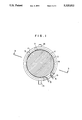
- FIG. 1 is a top view onto a holding arrangement according to the invention with a clamped-in lens
- FIG. 2 is a top view of the clasp of FIG. 1;
- FIG. 3 is a section through the holding arrangement of FIG. 1 taken along line 3--3 of FIG. 1;
- FIG. 4 is a view similar to FIG. 1, further comprising a rotating arrangement
- FIG. 5 illustrates the holding arrangement of FIG. 4, seen from the front in the direction of arrow 5 in FIG. 4;
- FIG. 6 is a top view depicting a substrate holding arrangement positioned in a flat holding structure or device
- FIG. 7 illustrates a multi-substrate holder in plan view
- FIG. 8 illustrates a further multi-substrate holder, disposed in a vapor deposition installation.
- FIG. 1 is a top view of substrate holding arrangement according to the invention.
- This is a lens holding device for holding tightly a lens 1, for example for disposing it in a working or coating installation.
- the lens 1 is clamped into a spring clasp 3, which is open on one side and which comprises at one end each on the open side one holding element or holding grip 5 by means of which the lens, clamped into the spring clasp 3, can be held.
- the spring clasp has bearing necks or supports 7 for supporting the spring clasp in receivers 11 of a holding device or a carrying ring 9.
- the carrying ring further has receivers 13 which are disposed essentially opposing the receivers 11.
- fastening elements 15 extending radially toward the outside.
- FIG. 2 is depicted in isolation the spring clasp 3 ready to receive a lens.
- lenses of different sizes can be received or clamped in with a spring clasp 3, such as is depicted in FIG. 2.
- the holding grips 5 are guided in the direction of the arrow more strongly toward each other or away from each other. The changing of the lenses can take place rapidly and simply.
- the spring clasp adapted to the peripheral contour of the substrate, can be implemented accordingly and must not necessarily be round as in the depicted example.
- FIG. 3 is depicted a section along line 3--3 of FIG. 1, in which it is clear that also lenses 1 having different thicknesses can be disposed in the clasp wherein advantageously an arcuate wall or one reaching beyond the substrate edge of the spring clasp can be used.
- a further advantage of the construction reaching around the substrate edge resides therein that substrates can be held in the edge region with low radial stress which is advantageous in particular for the reason that, as is known, certain substrate materials are sensitive to the action of force upon them.
- substrates such as optical lenses, comprising materials such as glass or synthetic material
- FIG. 4 shows again, analogously to FIG. 1, in top view a holding arrangement according to the invention for a substrate or a lens 1, wherein, however, the fastening elements 15 are implemented as supports for a rotating arrangement, further comprising a rotation lever 17, so that the carrying or holding ring can be rotated for example by 180°. In this way it becomes possible to work or to coat a lens 1 in a working installation sequentially on both side.
- FIG. 5 is depicted as a lateral view the view from FIG. 4 in the direction of arrow 5 depicting in particular the receiver 13 in the carrying or holding ring 9, for the reception of the two holding grips 5 of the spring clasp 3.
- the further receiver 13 comprises different snap-in positions 14 with which the two holding grips 5, depending on the size of the clamped-in lens 1, can each be clamped in several positions in one of the receivers 13.
- the substrate holding device depicted in FIGS. 1 to 5 has essential advantages compared to the known holding devices according to prior art, wherein the most important ones are the following:
- the lens to be coated is minimally shaded at the edge, i.e. for example less than 0.5 mm.
- the substrate holding devices depicted in FIGS. 1 to 5 are especially suited for the clamping and storing of substrates, such as lenses, in vacuum coating installations, which will be dealt with in greater detail with reference to FIGS. 6 and 7.
- FIG. 6 depicts a segment from a holding organ or device 19 with a substrate holder defined according to the invention, analogous to that of FIG. 4, wherein the holding organ 19 is provided and is suitable for the purpose of encompassing several substrate holders of this type.
- the flat holding organ 19 can be, for example, a carrier in the form of plates or vaulted sections in or on which several substrate holders of the described type are disposed for the reception and coating of substrates, such as for example lenses.
- an opening 18 in which the substrate holding device according to the invention is disposed, rotatably supported with the two fastening elements 15 in corresponding receivers on the holding device 19.
- the substrate holding device is disposed a lens 1, clamped in the spring clasp 3, in order to be coated in a vacuum installation disposed in the holding device 19.
- the lens 1 can, clamped in the substrate holding device, be rotated about 180° by means of the lever 17 about the two fastening elements 15, since due to the opening 18 the substrate holding device is freely rotatable in the carrier plate 19.
- the lens can also be coated on its back side.
- the advantage of the described rotation process resides therein that the coating of the back side can take place without long interruption of the working process and without opening the installation.
- FIG. 7 is depicted a whole segment of a plate-form holding organ 19 comprising a number of openings 18 intended for the disposition of substrate holding devices described according to the invention. It is clear in FIG. 7 that in the same holding organ 19 simultaneously several lenses can be coated and that by means of the above described rotation process the coating of the lens can take place on both sides.
- a separate rotating arrangement can be provided or the carrier plate can be rotated about a central axis wherein each of the rotation levers 17 depicted in FIG. 6, extends from each substrate holding device toward an angled stop whereby the substrates are rotated in simple manner.
- An angled mechanism of this type will be explained in further detail with reference to FIG. 8.
- the described holding organ 19 can be either a planar plate or also an arcuate surface. It is in every case essential that the substrate holders are disposed in such a way that they lie in the same plane. The selection of an appropriate surface arc depends in known manner on the dimensions of the vapor deposition arrangement.
- a vault-like holding organ 19 disposed in a vacuum chamber 23 of a vapor deposition installation 21.
- the vapor deposition installation 21 is therein depicted in lateral view from the front with the front opening removed so that the vault-like substrate holder 19 is visible.
- the vapor deposition installation 21 comprises an outlet opening 25 which leads for example to a vacuum pump 27 by means of which the working volume 23 can be evacuated.
- the vault-like holding organ 19 comprises in the openings 18 according to the invention the discrete substrate holding devices the depiction of which has been omitted for reasons of clarity.
- the holding organ 19 is further supported so as to be freely rotatable about an axis 29 so that the vault section during the vapor deposition from a vaporization source 31 can be rotated by means of a drive.
- This method of rotating with a drive about a central axis is in particular advantageous in order to be able to ensure a homogeneous layer thickness distribution.
- the vaporization source 31 can be for example an electron beam vaporization source.
- an angled mechanism 33 for rotating the discrete substrate holders is lowered by means of a lowering mechanism 37 toward the vault-like holding organ 19. If the angled mechanism 33 has been sufficiently lowered, the individual rotating hooks 35 engage the rotation levers 17 of the discrete substrate holding devices and, by rotating the holding organ 19 by 360°, all substrate holders are rotated about 180°.
- the angled mechanism 33 is again retracted by the lowering mechanism 37 and the coating process in the vapor deposition installation can be continued. It is therein of advantage if the same drive for the rotating motion of the vault-like holding organ 19 is also used for driving the lowering mechanism 37.
- FIGS. 1 to 8 are examples which are exclusively intended for a further explanation of the invention. It is understood, that it is possible to modify or to change the depicted embodiments in any desired manner and type; it is in particular possible for example to implement differently the support of the spring clasp 3 in a holding or carrying ring 9. It is also not absolutely necessary to provide a holding ring 9, and the holding device used for supporting the spring clasp 3 can also be for example square or rectangular or oval or be implemented in any other way and type.
- An essential part of the invention is the use of a spring clasp defined according to the invention which, together with a substrate to be clamped in, is supported in a holding device, for example for introducing it into a vacuum working installation.
Landscapes
- Chemical & Material Sciences (AREA)
- Physics & Mathematics (AREA)
- General Physics & Mathematics (AREA)
- Optics & Photonics (AREA)
- Chemical Kinetics & Catalysis (AREA)
- Engineering & Computer Science (AREA)
- Materials Engineering (AREA)
- Mechanical Engineering (AREA)
- Metallurgy (AREA)
- Organic Chemistry (AREA)
- Physical Vapour Deposition (AREA)
- Surface Treatment Of Optical Elements (AREA)
Applications Claiming Priority (2)
| Application Number | Priority Date | Filing Date | Title |
|---|---|---|---|
| CH3790/91 | 1991-12-19 | ||
| CH3790/91A CH684645A5 (de) | 1991-12-19 | 1991-12-19 | Substrathalte-Vorrichtung für Vakuumprozesse. |
Publications (1)
| Publication Number | Publication Date |
|---|---|
| US5325812A true US5325812A (en) | 1994-07-05 |
Family
ID=4263526
Family Applications (1)
| Application Number | Title | Priority Date | Filing Date |
|---|---|---|---|
| US07/988,728 Expired - Fee Related US5325812A (en) | 1991-12-19 | 1992-12-10 | Substrate holding and rotating arrangement for vacuum processes |
Country Status (3)
| Country | Link |
|---|---|
| US (1) | US5325812A (de) |
| EP (1) | EP0547312A1 (de) |
| CH (1) | CH684645A5 (de) |
Cited By (15)
| Publication number | Priority date | Publication date | Assignee | Title |
|---|---|---|---|---|
| US5549754A (en) * | 1991-04-30 | 1996-08-27 | Murata Manufacturing Co., Ltd. | Lead frame holder |
| EP0913717A4 (de) * | 1997-05-16 | 2000-01-05 | Hoya Kabushiki Kaisha | Vorrichtung zum einsetzen eines linsenrohlings in einen halter |
| EP0992607A1 (de) * | 1998-10-07 | 2000-04-12 | Applied Vision Ltd | Substrat-Träger |
| US6193801B1 (en) * | 1997-04-18 | 2001-02-27 | Semi-Alloys Company | Apparatus for coating lenticular articles |
| US6473247B1 (en) * | 1998-09-04 | 2002-10-29 | Essilor International | Optical lens support and method for using same |
| WO2006069774A3 (de) * | 2004-12-28 | 2006-10-05 | Schott Ag | Vakuumbeschichtungssystem |
| US20090038544A1 (en) * | 2007-08-08 | 2009-02-12 | Hon Hai Precision Industry Co., Ltd. | Film coating holder and film coating device using same |
| US20090229514A1 (en) * | 2008-03-17 | 2009-09-17 | Hon Hai Precision Industry Co., Ltd. | Film coating cover and film coating device using same |
| WO2011013648A1 (ja) * | 2009-07-30 | 2011-02-03 | Hoya株式会社 | 光学レンズの蒸着装置 |
| WO2012151340A1 (en) * | 2011-05-05 | 2012-11-08 | Varian Semiconductor Equipment Associates, Inc. | Media carrier |
| US20140240859A1 (en) * | 2013-02-28 | 2014-08-28 | Corning Incorporated | Optic obscuration assembly, method and system for working on an optical element, and resulting optical element |
| DE102017003224A1 (de) * | 2016-09-06 | 2018-03-08 | Schneider Gmbh & Co. Kg | Anordnung und Verfahren zum Halten eines optischen Werkstücks sowie optisches Werkstück und Brille |
| EP3392371A1 (de) * | 2017-04-19 | 2018-10-24 | Vestel Elektronik Sanayi ve Ticaret A.S. | Werkzeug zur fixierung von substraten in einem pvd-verfahren |
| IT201900002339A1 (it) * | 2019-02-18 | 2020-08-18 | Thelios S P A | Metodo per realizzare una lente di occhiali rivestita mediante deposizione fisica di vapore pvd e corpo di supporto per uno sbozzato di lente |
| CN113853274A (zh) * | 2019-01-30 | 2021-12-28 | 卡尔蔡司光学国际有限公司 | 用于将光学镜片引入到转动装置中的设备和方法 |
Families Citing this family (6)
| Publication number | Priority date | Publication date | Assignee | Title |
|---|---|---|---|---|
| DE4446179C2 (de) * | 1994-12-23 | 2003-08-21 | Leybold Optics Gmbh | Halterung für scheibenförmige Substrate |
| DE10146542B4 (de) * | 2001-09-21 | 2005-03-03 | Dieter Henrich | Handhabung von Gegenständen, wie Linsen |
| DE102004026523A1 (de) * | 2004-05-25 | 2005-12-22 | Carl Zeiss Smt Ag | Verfahren zur Handhabung von Optikkomponenten und dazu geeignetes Handhabungssystem |
| FR2895521B1 (fr) * | 2005-12-23 | 2008-02-01 | Essilor Int | Installation et procede de revetement pour lentille ophtalmique. |
| DE102006012747B4 (de) * | 2006-03-17 | 2010-07-01 | Carl Zeiss Ag | Kalotte mit einer Mehrzahl an Vorrichtungen zum Halten sowie zum Drehen und/oder Wenden eines Gegenstands bei dessen Beschichtung in einer Vakuumbeschichtungsanlage sowie Verfahren zum Halten sowie zum Drehen und/oder Wenden von Gegenständen bei deren Beschichtung in einer Vakuumbeschichtungsanlage |
| DE102017117037A1 (de) * | 2017-07-27 | 2019-01-31 | Technische Hochschule Deggendorf | Fixiervorrichtung |
Citations (3)
| Publication number | Priority date | Publication date | Assignee | Title |
|---|---|---|---|---|
| US4412504A (en) * | 1980-07-28 | 1983-11-01 | Siemens Aktiengesellschaft | Device for holding substrate wafers |
| US4817559A (en) * | 1986-07-31 | 1989-04-04 | Satis Vacuum Ag | Vacuum vapor-deposition apparatus for coating an optical substrate |
| US5124019A (en) * | 1989-07-01 | 1992-06-23 | Leybold Aktiengesellschaft | Lens holder for use in a high-vacuum vapor deposition or sputtering system |
Family Cites Families (1)
| Publication number | Priority date | Publication date | Assignee | Title |
|---|---|---|---|---|
| US2532971A (en) * | 1947-04-12 | 1950-12-05 | Pacific Universal Products Cor | Method and apparatus for producing optical coatings |
-
1991
- 1991-12-19 CH CH3790/91A patent/CH684645A5/de not_active IP Right Cessation
-
1992
- 1992-10-07 EP EP92117086A patent/EP0547312A1/de not_active Withdrawn
- 1992-12-10 US US07/988,728 patent/US5325812A/en not_active Expired - Fee Related
Patent Citations (3)
| Publication number | Priority date | Publication date | Assignee | Title |
|---|---|---|---|---|
| US4412504A (en) * | 1980-07-28 | 1983-11-01 | Siemens Aktiengesellschaft | Device for holding substrate wafers |
| US4817559A (en) * | 1986-07-31 | 1989-04-04 | Satis Vacuum Ag | Vacuum vapor-deposition apparatus for coating an optical substrate |
| US5124019A (en) * | 1989-07-01 | 1992-06-23 | Leybold Aktiengesellschaft | Lens holder for use in a high-vacuum vapor deposition or sputtering system |
Cited By (21)
| Publication number | Priority date | Publication date | Assignee | Title |
|---|---|---|---|---|
| US5549754A (en) * | 1991-04-30 | 1996-08-27 | Murata Manufacturing Co., Ltd. | Lead frame holder |
| US6193801B1 (en) * | 1997-04-18 | 2001-02-27 | Semi-Alloys Company | Apparatus for coating lenticular articles |
| EP0913717A4 (de) * | 1997-05-16 | 2000-01-05 | Hoya Kabushiki Kaisha | Vorrichtung zum einsetzen eines linsenrohlings in einen halter |
| US6187159B1 (en) | 1997-05-16 | 2001-02-13 | Hoya Corporation | Mechanism for setting optical lens base material on holder |
| US6473247B1 (en) * | 1998-09-04 | 2002-10-29 | Essilor International | Optical lens support and method for using same |
| EP0992607A1 (de) * | 1998-10-07 | 2000-04-12 | Applied Vision Ltd | Substrat-Träger |
| WO2006069774A3 (de) * | 2004-12-28 | 2006-10-05 | Schott Ag | Vakuumbeschichtungssystem |
| US20090038544A1 (en) * | 2007-08-08 | 2009-02-12 | Hon Hai Precision Industry Co., Ltd. | Film coating holder and film coating device using same |
| US8105438B2 (en) * | 2008-03-17 | 2012-01-31 | Hon Hai Precision Industry Co., Ltd. | Film coating cover and film coating device using same |
| US20090229514A1 (en) * | 2008-03-17 | 2009-09-17 | Hon Hai Precision Industry Co., Ltd. | Film coating cover and film coating device using same |
| WO2011013648A1 (ja) * | 2009-07-30 | 2011-02-03 | Hoya株式会社 | 光学レンズの蒸着装置 |
| WO2012151340A1 (en) * | 2011-05-05 | 2012-11-08 | Varian Semiconductor Equipment Associates, Inc. | Media carrier |
| US8746666B2 (en) | 2011-05-05 | 2014-06-10 | Varian Semiconductor Equipment Associates, Inc. | Media carrier |
| US20140240859A1 (en) * | 2013-02-28 | 2014-08-28 | Corning Incorporated | Optic obscuration assembly, method and system for working on an optical element, and resulting optical element |
| DE102017003224A1 (de) * | 2016-09-06 | 2018-03-08 | Schneider Gmbh & Co. Kg | Anordnung und Verfahren zum Halten eines optischen Werkstücks sowie optisches Werkstück und Brille |
| EP3392371A1 (de) * | 2017-04-19 | 2018-10-24 | Vestel Elektronik Sanayi ve Ticaret A.S. | Werkzeug zur fixierung von substraten in einem pvd-verfahren |
| CN113853274A (zh) * | 2019-01-30 | 2021-12-28 | 卡尔蔡司光学国际有限公司 | 用于将光学镜片引入到转动装置中的设备和方法 |
| CN113853274B (zh) * | 2019-01-30 | 2023-10-24 | 卡尔蔡司光学国际有限公司 | 用于将光学镜片引入到转动装置中的设备和方法 |
| IT201900002339A1 (it) * | 2019-02-18 | 2020-08-18 | Thelios S P A | Metodo per realizzare una lente di occhiali rivestita mediante deposizione fisica di vapore pvd e corpo di supporto per uno sbozzato di lente |
| EP3695959A1 (de) * | 2019-02-18 | 2020-08-19 | The'Lios S.p.A. | Verfahren zur herstellung eines mittels physikalischer dampfphasenabscheidung (pvd) beschichteten brillenglases und zwischenanordnung zur herstellung eines beschichteten brillenglases für dieses verfahren |
| US11774777B2 (en) | 2019-02-18 | 2023-10-03 | The'lios S.P.A. | Method for making an eyeglass lens coated by means of physical vapor deposition PVD |
Also Published As
| Publication number | Publication date |
|---|---|
| CH684645A5 (de) | 1994-11-15 |
| EP0547312A1 (de) | 1993-06-23 |
Similar Documents
| Publication | Publication Date | Title |
|---|---|---|
| US4817559A (en) | Vacuum vapor-deposition apparatus for coating an optical substrate | |
| US8356808B2 (en) | Apparatus for turning over an article in a vacuum coating system and method for turning over said article in a vacuum coating system | |
| US5124019A (en) | Lens holder for use in a high-vacuum vapor deposition or sputtering system | |
| US6082298A (en) | Substrate carrier for a vacuum coating apparatus | |
| US6473247B1 (en) | Optical lens support and method for using same | |
| TWI794475B (zh) | 用於接收多個基板以進行處理之保持裝置、處理系統及方法 | |
| US5138974A (en) | Vacuum apparatus for coating an optical substrate | |
| GB2156861A (en) | Holder device for substrates in vaccum deposition apparatus | |
| US4643128A (en) | Multiple holder for substrates to be treated | |
| EP4112770B1 (de) | Halter zum halten eines substrats, insbesondere eines brillenglases, während der vakuumbeschichtung desselben in einer vakuumkammer-beschichtungsvorrichtung und vorrichtung zum laden/entladen des substrats in einen/aus einem solchen halter | |
| CH684645A5 (de) | Substrathalte-Vorrichtung für Vakuumprozesse. | |
| US12129540B2 (en) | Apparatus and method for introducing an optical lens into a turning device | |
| US4344383A (en) | Retainer ring for securing substrates in a vacuum deposition system | |
| KR102742179B1 (ko) | 코팅 스테이션용 광학 요소 홀더 디바이스 | |
| EP0806493A3 (de) | Vakuum-Beschichtungsanlage zum Aufdampfen von Vergütungsschichten auf optische Substrate | |
| JP3412849B2 (ja) | 薄膜蒸着装置 | |
| US20210381100A1 (en) | Vacuum treatment apparatus and method of vacuum treating substrates | |
| JPH04329869A (ja) | 蒸着装置及び蒸着方法 | |
| KR101152103B1 (ko) | 렌즈 코팅용 진공 증착기의 투시구 | |
| JP2005200214A (ja) | 基板支持体アダプタシステム | |
| KR100248703B1 (ko) | 양면 사용 절삭공구의 코팅장치 | |
| EP2111479B1 (de) | Halter für eine optische linse | |
| EP0992607A1 (de) | Substrat-Träger | |
| JP2002348661A (ja) | プリズム面の蒸着装置およびその方法 | |
| JPH1046339A5 (de) |
Legal Events
| Date | Code | Title | Description |
|---|---|---|---|
| AS | Assignment |
Owner name: BALZERS AKTIENGESELLSCHAFT, LIECHTENSTEIN Free format text: ASSIGNMENT OF ASSIGNORS INTEREST;ASSIGNORS:THIEBAUD, FRANCIS;STINGL, FRIEDRICH;REEL/FRAME:006752/0546 Effective date: 19930208 |
|
| FEPP | Fee payment procedure |
Free format text: PAYOR NUMBER ASSIGNED (ORIGINAL EVENT CODE: ASPN); ENTITY STATUS OF PATENT OWNER: LARGE ENTITY |
|
| FPAY | Fee payment |
Year of fee payment: 4 |
|
| FPAY | Fee payment |
Year of fee payment: 8 |
|
| REMI | Maintenance fee reminder mailed | ||
| LAPS | Lapse for failure to pay maintenance fees | ||
| STCH | Information on status: patent discontinuation |
Free format text: PATENT EXPIRED DUE TO NONPAYMENT OF MAINTENANCE FEES UNDER 37 CFR 1.362 |
|
| FP | Lapsed due to failure to pay maintenance fee |
Effective date: 20060705 |