US5329599A - Enhanced fidelity reproduction of images by hierarchical template matching - Google Patents
Enhanced fidelity reproduction of images by hierarchical template matching Download PDFInfo
- Publication number
- US5329599A US5329599A US08/146,629 US14662993A US5329599A US 5329599 A US5329599 A US 5329599A US 14662993 A US14662993 A US 14662993A US 5329599 A US5329599 A US 5329599A
- Authority
- US
- United States
- Prior art keywords
- pattern
- pixel
- sub
- patterns
- pixels
- Prior art date
- Legal status (The legal status is an assumption and is not a legal conclusion. Google has not performed a legal analysis and makes no representation as to the accuracy of the status listed.)
- Expired - Lifetime
Links
Images


Classifications
-
- G—PHYSICS
- G06—COMPUTING OR CALCULATING; COUNTING
- G06K—GRAPHICAL DATA READING; PRESENTATION OF DATA; RECORD CARRIERS; HANDLING RECORD CARRIERS
- G06K15/00—Arrangements for producing a permanent visual presentation of the output data, e.g. computer output printers
Definitions
- the present invention relates to improvement in the display of raster images, and in particular to enhancing the exposure fidelity in increased precision optical display systems. More specifically, the invention pertains to economical and technically attractive methods and means for enhancing the contour fidelity of exposures on a microaddressable optical printer.
- Walsh et al. U.S. Pat. No. 4,437,122, describes a method of enhancing the resolution and quality of characters of a system receiving video display pixel information and providing hard copy output.
- the system accomplishes this by storing at least three successive lines of video data in successive parallel connected shift registers, applying the output of the shift registers to a decoder, and generating driving signals for a printer head.
- the decoder "compares the pixels on the same lines as well as in preceding and succeeding lines that surround each specific input pixel to generate the printer head driving signal according to whether straight or curved line segments are to be formed".
- line 67, to column 4, line 1 the enhancement of the central pixel may be determined by "progressively examining an ordered table of matches to find an equivalent image and its related enhancement.”
- Template matching effectively overcomes some of the sampling errors that are caused by the use of input data that is too coarse to accurately represent the higher spatial frequency content of the image. It does not, however, solve the problems that may be encountered in existing printers due to non-linearity in the way in which the spatial positioning of the transitions in printed images tracks changes in the intensity of the transitional boundary scans.
- ROS raster output scanners
- a single beam or a multi-beam laser light source for supplying one or more intensity modulated light beams, together with a scanner (such as polygon scanner) for cyclically deflecting the modulated laser beam or beams across a photoreceptor in a "fast scan direction" while the photoreceptor is being advanced simultaneously in an orthogonal "process direction.”
- a scanner such as polygon scanner
- each of the laser beams typically is brought to focus on or near the photoreceptor surface to provide a substantially focused "scan spot.”
- the scan spot scans the photoreceptor in accordance with a predetermined scan pattern because the fast scan deflection of the laser beam or beams vectorially sums with the process direction motion of the photoreceptor.
- the scan pattern is dependent upon and is determined by the scan rate (scan/sec) of the scanner, the spot size that is employed, and the process speed (inches/sec) of the photoreceptor.
- Such a scan pattern produces an exposure pattern because the scans are superpositioned on the photoreceptor, regardless of whether the scans simultaneously or sequentially expose the photoreceptor. Accordingly, it is to be understood that the present invention applies to printers and other display means that employ single beam or multi-beam ROSs, even though this disclosure features the single beam/single scan spot case for the sake of simplification.
- Microaddressable printers and other types of display systems operate in an overscanned mode to render images by scanning one or more intensity modulated scan spots over a high gamma, photosensitive recording medium in accordance with a scan pattern that causes the spot or spots to superimpose multiple discrete exposures on the recording medium on centers that are separated by a pitch distance that is significantly less than the effective spatial diameter of the scan spot (i.e., the full width/half maximum (FWHM) diameter of a gaussian scan spot).
- FWHM full width/half maximum
- Overscanned systems have substantially linear addressability responses, so boundary scans that are intensity modulated in accordance with the preselected offset values are used by these systems for spatially positioning the transitions that are contained by the images they render to a sub-pitch precision.
- the output resolution is limited to the scan resolution.
- double overscanned printing there are twice as many scans, effectively doubling the resolution scans in the process direction.
- the power to the laser diode, or "intensity" of each scan can be controlled during the scan, giving subscan addressability. For example, in a printer with a spot size of 1/400 inch, scanning would take place at 800 scans per inch. At four levels of gray, the addressability of the printer increased to 3200 bits per inch.
- a limited overscan is, however, consistent with the printing of high quality images because it permits the image transitions (i.e., the high spatial frequency content of the images) to be mapped onto the scan pattern with increased spatial precision.
- the present invention provides a method for enhancing the contour fidelity of images.
- the method includes isolating a window of pixels in a portion of the image and comparing pixels in the window with a hierarchical set of standard pixel patterns which include correctable pixel positions. Matching patterns are identified, and the central pixel of the window is enhanced when it lies in a correctable position in the highest priority pattern that is matched.
- the present invention also provides a template matching technique with a double overscanned ROS to achieve enhanced fidelity exposures. Furthermore, the technique of the present invention may compensate for the width of a spot in both the fast scan and process directions. The technique of the present invention serves to smooth contours and jagged or stair-stepped edges commonly found in bitmapped images.
- One aspect of the invention is based on the recognition of a problem with conventional and overscanned printing utilized to render enhanced exposure fidelity to a photoreceptor or other recording media.
- the source of the high fidelity information is a sampled image or a high resolution bitmap.
- many raster data sources provide low resolution bitmaps at 300 or 400 bits per inch, which is not enough resolution to eliminate unwanted artifacts induced by the coarseness of the information, such as stairstepping.
- Another aspect of the invention is based on the recognition of a problem with other techniques in a conventional printer where the scan spacing is the same as the spot resolution, which does not compensate for the width of the spot.
- This aspect is further based on the discovery that this problem can be solved by an extension to a 2 ⁇ overscanned printer, which gives the advantage of having a more linear edge positioning response with respect to intensity, thereby reducing the number of required correction intensities, as well as simplifying and making the edge positions more predictable.
- the technique of the invention further compensates for the width of the spot when rendering all bitmapped data, thereby reducing distortion of shapes when the object being rendered is one or two bits wide.
- the hierarchial and permutation strategy of the invention has the advantage of simplifying the implementation.
- Pattern templates are implemented in a hierarchial arrangement, in which the largest pattern which receives a match will have priority over smaller patterns. Patterns are arranged so that a match on any pattern in general is simply the combination of a match on the next lowest pattern plus two additional bits, saving gate resources in the decoding logic.
- FIG. 1 shows general features of a laser printer.
- FIG. 2 shows an application of microaddressability in 2 ⁇ overscanned output device to a portion of a bitmap.
- FIG. 3 shows set of patterns which represent a hierarchy of patterns for recognition of low fidelity bits which are to be enhanced.
- FIG. 4 shows a set of horizontal and vertical templates based on permutations of pattern 4 from FIG. 3.
- FIG. 5 shows a set of horizontal and vertical templates based on permutations of impulse match pattern 4 from FIG. 3.
- FIG. 6 shows an input window used to determine the area of the image.
- FIG. 7 shows a portion of an image in an input window similar to FIG. 6.
- FIG. 8 illustrates an enhancement application in a group of pixels.
- FIG. 9 shows the resulting enhancement values of pixels in a pattern as a result of the operations shown in FIG. 8.
- FIG. 10 shows pixels, indicated in bold, which need to be corrected when horizontal templates are matched.
- FIG. 11 shows pixels, indicated in bold, which need to be corrected when vertical templates are matched.
- FIG. 12 shows a flowchart illustrating steps in enhancing a portion of an image.
- FIG. 13 shows an example of multiple templates permutated from pattern 5 matching a portion of text.
- FIG. 14 shows a block diagram of an apparatus for performing the image enhancement in accordance with the present invention.
- FIG. 15 shows a portion of an image.
- FIGS. 16-19 show typical implementations of template detecting circuitry.
- FIG. 20 shows an improved circuit implementation which detects matches with hierarchial templates.
- An “image” is a pattern of light.
- An image may include characters, words, and text as well as other features such as graphics.
- An “image output device” is a device that can provide an image as output.
- a “display” is an image output device that provides information in visible form. The visible pattern presented by a display is an "image”.
- Each location in an image may be called a "pixel.”
- each value indicating the color or intensity of a location may be called a "pixel value”.
- the two-dimensional array of pixels defining the image may be "binary form” or “bitmapped,” or a "gray-scale form.”
- Each pixel value is a "bit” in the binary form or bitmap of the image, or a "gray-scale intensity value” in a gray-scale form of the image.
- An edge of an image may be described as a “contour” that may have a "slope” or angle.
- FIGS. 1 and 2 show general features and application of an overscanned laser printer.
- FIG. 1 there is illustrated a more or less conventionally configured optical system 10 of a xerographic print engine (not shown).
- the flying spot ROS scans a data modulated light beam 12 over a xerographic photoreceptor 14 in accordance with a predetermined raster scanning pattern.
- the ROS comprises a laser diode 16 for emitting the light beam 12 in the visible or invisible (e.g., infrared) band of the spectrum, together with a polygon scanner 18 that has a plurality of nearly identical, mirror-like exterior sidewalls or "facets" 20.
- the scanner 18 there is a motor 22 for rotating the scanner 18 about its central axis, as indicated by the arrow 24, at a substantially constant angular velocity.
- the scanner 18 is optically aligned between the laser 16 and the photoreceptor 14, so its rotation causes the laser beam 12 to be intercepted and reflected from one after another of the scanner facets 20, with the result that the beam 12 is cyclically swept across the photoreceptor 14 in a fast scan direction.
- the photoreceptor 14, is advanced (by means not shown) simultaneously in an orthogonal, process direction at a substantially constant linear velocity, as indicated by the arrow 26, so the laser beam 12 scans the photoreceptor 14 in accordance with a raster scan pattern.
- the photoreceptor 14 is coated on a rotating drum 28, but it will be apparent that it also could be carried by a belt or any other suitable substrate.
- the ROS additionally includes pre-scan optics 30 and post-scan optics 32 for bringing the laser beam 12 to a generally circular focus proximate the photoreceptor 14 and for providing any optical correction that may be needed to compensate for scanner wobble and other optical irregularities.
- the optical aperture of the ROS is sufficiently large to avoid excessive truncation of the laser beam 12 because the beam 12 then comes to a generally circular or elliptical focus with a gaussian intensity profile.
- the broader aspects of this invention are not limited to any specific scan spot geometry or intensity profile. Accepted design principles indicate that the spatial frequency power spectrum of the scan spot profile should not have significant spatial frequency components outside the spatial frequency passband of the imaging system, but the scan spot can otherwise be tailored to satisfy a variety of system requirements.
- the amplitude, duty cycle, and/or pulse width of the laser beam 12 is serially modulated (collectively referred to herein as "intensity modulation") in accordance with successive multi-bit digital data values.
- These data values are clocked out of a data source 36 serially in response to data clock pulses which are time synchronized with the scan of the scan spot from bitmap location-to-bitmap location within the raster scan pattern.
- the data clock frequency can be selected (by means not shown) to map the data onto the raster scan pattern at any desired magnification, using either the same or different magnifications in the fast scan and the process directions.
- the data may be preprocessed (by means not shown) for the printing of halftoned images and/or text and other types of line art, so the data source 36 generically represents any suitable source of raster data for intensity modulating the laser beam 12.
- the drive current for the laser diode 16 is serially modulated by modulator 38 in accordance with the data values that are clocked out of the data source 36, thereby intensity modulating the laser beam 12 at the data clock rate in accordance with those data values.
- the fast scan positioning precision of the print engine 10 can be increased, if desired, by dynamically adjusting the frequency of the data clock to compensate for positioning errors that tend to be caused by "motor hunt” (i.e., variations in the angular velocity of the scanner 18), "polygon signature” characteristics (variations in the angular velocities at which the different facets 20 of the scanner 18 sweep the scan spot across the photoreceptor 14 from a start-of-scan position to an end-of-scan position), and "scan non-linearities” (i.e., localized variations in the linear velocity of the fast scan, which are caused by variances in the geometric relationship of the scanner 18 to spatially distinct segments of any given scan line).
- "motor hunt” i.e., variations in the angular velocity of the scanner 18
- polygon signature characteristics
- scan non-linearities i.e., localized variations in the linear velocity of the fast scan, which are caused by variances in the geometric relationship of the scanner 18 to spatially distinct segments of any
- the pitch of the scan pattern for the printer 10 is selected to be significantly finer (i.e., smaller) than the FWHM diameter of the scan spot that is formed from the scan beam 12.
- This relatively fine pitch scan pattern causes the printer 10 to operate in an "overscanned" mode because the FWHM central core of the scan spot sweeps across spatially overlapping segments of the photoreceptor 14 during the scanning of spatially adjacent, neighboring scan lines. Overscanning slightly degrades the spatial frequency response of the printer 10 in the process direction.
- the linearity of the addressability response of ROS printers, such as printer 10 increases rapidly as the ratio of the scan pitch to the FWHM diameter of the scan spot is reduced to progressively smaller, sub-unity values (i.e., increasing the overscan).
- overscanning is the key to providing the essentially linear position control that enables discrete exposures to map image transitions onto a scan pattern at a sub-resolution precision.
- a relatively small loss of process direction frequency response is accepted to achieve substantially increased process direction addressability.
- FIG. 2 shows an example of the application of microaddressability by overscanning in a 2 ⁇ overscanned output device.
- Central pixel 50 is surrounded by other pixels, such as pixel 52.
- the fast scan direction 54 is shown in a horizontal direction
- the slow scan, or process direction 58 is shown vertically.
- scan trajectories 56 and 57 show how double scanning increases the addressability of segments of each pixel by a factor of two.
- the addressability in the slow scan direction is increased by another factor of four due to four levels of intensity adjustment in the ROS.
- the addressability is increased by a factor of four by increasing the clock frequency.
- Each pixel is thereby represented by eight segments, each of which may have one of four different intensity levels.
- the enhanced printer would have 1600 addressability in the fast scan direction, and 3200 addressability in the slow scan direction. These parameters may be modified depending on target design goals.
- Scan spots 60-66 show example scan spot sizes corresponding to a 2 ⁇ overscanned printer, as described in copending, coassigned U.S. patent application Ser. No. 07/736,989, incorporated herein by reference.
- Scan spot 60 shows an example scan spot size corresponding to intensity 1.
- Scan spot 62 shows an example scan spot size corresponding to intensity 2.
- Scan spot 64 shows an example scan spot size corresponding to intensity 3.
- Scan spot 66 shows an example scan spot size corresponding to intensity 4.
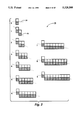
- FIG. 3 shows a pattern set 70 of "patterns" which represent a hierarchy of patterns for recognition of low fidelity bits which are to be enhanced.
- Printers or other devices which use template matching can use these patterns to detect edge lines which may be slightly horizontal or slightly vertical.
- the set is a "hierarchy" of ten patterns, in which the next higher member of the set is a composite of the previous member in the hierarchy and an extension pattern of two additional bits. This method of obtaining patterns saves gate resources in implementation, in that any pattern is simply the combination of the next lower priority pattern plus two additional bits, one "on” and the other "off".
- the highest priority pattern is pattern 9, but fewer or more patterns may be utilized.
- the patterns are designed to find the slope of portions of edges, or contours, in an image.
- the largest, or highest, pattern which receives a match will have priority over smaller patterns, and the enhancement called for by that particular pattern will be utilized. If no pattern matches, then the portion of the image being examined is not an edge, and no enhancement action is taken.
- Pattern 0 will be identified as a match at any edge transition from white to black.
- Higher priority patterns are extensions of pattern 0, each with two additional bits, which will match edges that are not precisely horizontal or vertical. For example, line 74 shows an edge line that is precisely horizontal which is matched by pattern 0.
- Pattern 1, which has a "run-length" of 1 will match an edge approximately 45° from horizontal, shown by line 76. As the run-length of patterns increases, the angle of the edge that each pattern will match gets closer to horizontal.
- Pattern 9 has a run-length of 9.
- FIGS. 4 and 5 show a set of templates created from pattern 4.
- pattern 4 is rotated and mirrored in the horizontal and vertical directions to produce a set of 16 templates.
- Template a h describes the basic pattern.
- Template b h is the complement of the basic pattern. Together, these two templates are called an "impulse pair"
- templates a h and b h are rotated 180° another impulse pair is created by templates c h and d h .
- templates c h and d h are then mirrored, creating two additional impulse pairs made up of templates e h and f h and templates g h and h h .
- Templates a h -h h are herein referred to as "horizontal" templates, and templates a v -h v are herein referred to as “vertical” templates. Templates a h -h h and a v -h v are herein referred to as "permutations" of pattern 4.
- a match of both templates of an impulse pair denotes the existence of an "impulse match" denoting a black or white line with a width of one bit.
- matches for both templates in an impulse pair occur, they may be treated differently that when only one template from the impulse pair is recognized or if both templates in the pair were matched independently, and different enhancement information may be output.
- Matches for single templates of an impulse pair denote transitions from black to white or white to black over widths wider than a single bit.
- a basic impulse match may be rotated and mirrored in both the horizontal and vertical directions in the same way that the basic pattern was in FIG. 4, to create an additional 16 templates.
- Each pattern in the hierarchical set 70 may be used to create a similar set of 32 templates of different permutations. Additional patterns or combinations of patterns or templates with different extension patterns may be combined to recognize other objects such as crossed lines and corners.
- FIG. 6 shows an input window 80 to be used to determine the area of the image to be matched by the templates.
- An input window is defined as the area of the input low resolution bitmap over which patterns can be found.
- Central pixel 82 is the pixel which will receive enhanced correction information.
- Input window 80 is shown with a size of 11 ⁇ 11 pixels. However, size of the input window is important only to the extent that it allows the recognition of all patterns, It may be adjusted up or down in size in the design as required.
- the technique of the invention makes symmetrical corrections-that is, corrections can be made to the vertical direction with the same precision as in the horizontal direction, to either side of the center point.
- a window that is as tall as it is wide, with an equal number of pixels along each axis to each side of the center point, is called a "symmetrical" window.
- the side of the window that is truncated by the edge of the image is considered to be filled with "off" pixels.
- An input window of size 11 ⁇ 11 is appropriate for the hierarchical set of patterns 70 in FIG. 3.
- Pattern 6, with a run-length of 6, fits entirely within the window at its first correctable pixel at the center pixel location. It can be shown that patterns of larger run-length, such as pattern 9, will also fit. In consideration of current economics of design and of output resolution capabilities, patterns of run-lengths of greater than 6 may not give discernibly better results than achieved using a hierarchy that includes patterns 0-6.
- FIG. 7 shows a portion of an image 90 in input window 80. As shown, a portion of the image matches pattern 7, but only the portion matching pattern 6 is visible inside the window. Pixel 82, the central pixel, is in a correctable position for both pattern 6 and 7, but will receive enhancement information corresponding to pattern 6. As the window shifts locations over the image, other correctable pixels in the pattern may be detected.
- FIG. 8 illustrates an enhancement of a group of pixels forming a portion of an image.
- Group 110 encompasses a group of pixels that matches pattern 4, permutation a h , as shown in FIG. 4. For this example, it is assumed that this portion of the image does not match any impulse match template (i.e., the width of the image represented in part by the pixel group is greater than 1 pixel wide), or any higher priority template.
- Lines 122 and 124 illustrate the first and second scan lines, respectively, of the overscan. Marks 126 show the clock frequency in the fast scan direction.
- Line 132 shows the trajectory of the line of the edge illustrated by the group of pixels.
- Line 134 shows the corrected edge in the enhancement.
- the enhanced edge is one half of the maximum spot diameter from the original trajectory.
- the central pixel can be divided into eight segments, each with a different gray level or intensity value.
- the first pixel to be corrected is pixel 120.
- pixel 120 In the original image input, pixel 120 is entirely white.
- the first, or top scan of this pixel will also be entirely white.
- Correction of the pixel to the enhanced edge will be made in the second, or bottom scan of pixel 120.
- Scan spot 136 shows a spot of intensity 2 that significantly fills in the area between the original trajectory and the enhanced edge to correct the line at the first clock cycle.
- Scan spot 138 of intensity 1 significantly fills in the area to the enhanced edge at the second clock cycle.
- Scan spot 140 also has an intensity of 1 at the third clock cycle.
- Correction may also be made to pixel 128.
- a scan spot of intensity 4 shown by scan spot 144, is needed.
- Scan spot 146 at the second clock cycle has an intensity of 3.
- Scan spot 148, at the third clock cycle also has an intensity of 3.
- Scan spot 150 has an intensity of 2 at the fourth clock cycle.
- the second scan of pixel 128 needs no correction, so scan spots of intensity 4 will be output at each clock cycle.
- the expanded segment pattern of corrected values of pixel 128 is then 4332 and 4444 for the first and second scans, respectively.
- FIG. 9 shows the resulting expanded pattern of intensity values according to the method performed in FIG. 8.
- pixel 120 When pixel 120 is in the central pixel position of window 80 of FIG. 6 when a match with template 4 permutation a h is found, it will be enhanced with segments with gray level intensities of 0 0 0 0 in the first scan, and 2 1 1 0 in the second scan.
- pixel 128 when pixel 128 is the central pixel, it will be enhanced with segments with gray level intensities of 4 3 3 2 and 4 4 4 4, shown in Table 1. If a match with this pattern is made when pixel 130 is in the central pixel position, no enhancements are made according to this pattern and the segments represent the original pixel. However, pixel 130 is likely to fall in the correctable range of another template.
- Tables 1 or 2 could be used to determine the enhancement values of segments for the central pixel. If a permutation of an impulse match of pattern 4 was the highest priority match, Tables 3 or 4 could be used to determine the enhancement values of segments for the central pixel.
- pixels 120 and 128 are the only pixels to be corrected in this pixel group. Values for pixel 120 are shown in the Pixel 2 column in Table 1. Values for pixels which occur in the position of pixel 128 are shown in the Pixel 1 column.
- Tables 1-4 show enhancement values of segments for the pixels which will be enhanced in pattern 4 for different permutations and impulse match permutations. Similar tables of enhancement values for horizontal, vertical and impulse match templates up to run-length of 6 are found in Appendix A. The tables in Appendix A may be used to find the enhancement values for correctable pixels in templates of different run-lengths.
- Tables 1 and 2 show templates which are permutations of basic pattern 4, Table 1 showing enhancement values for horizontal permutations, and Table 2 showing enhancement values for vertical permutations.
- the enhancement value for the central pixel is shown in one of the two columns, Pixel1 or Pixel2, depending on where in the pattern the central pixel lies.
- the data in these tables has been determined empirically. Small variations in the intensity of enhancement values of segments are likely to be imperceptible when output. Similarly, patterns which are longer than run-length 6 may not produce perceptibly better enhanced results when output, depending on the resolution of the output medium.
- Tables 3 and 4 show enhancement values for the segments for pixels in impulse matches for pattern 4. For each impulse match template which is permuted from pattern 4, the enhancement values for the central pixel are shown in one of the four columns, according to where in the pattern the central pixel lies. Table 3 shows the values for horizontal impulse match templates, and Table 4 shows the values for vertical impulse match templates.
- the flowchart of FIG. 12 shows steps in enhancing a portion of an image.
- the step in box 220 stores consecutive lines of an image.
- the step in box 222 isolates a portion of the image.
- the step in box 224 forms a window in the isolated portion of the image. This window may be a symmetrical set of pixels around a central pixel.
- the step in box 226 generates an identifier describing the pixel pattern.
- the step in box 228 compares the identifier of the window with the identifiers of known pixel patterns, or templates.
- the step in box 230 finds the highest priority template that is matched.
- the step in box 232 enhances the central pixel, according to the correction data for the highest priority matched template. If more than one template for a given pattern is detected and a pixel is correctable in both, enhancement information for the template corresponding to the lowest alphanumeric is given priority.
- Template 252 shows that template a h based on pattern 5 matches on the portion of the image.
- Template 254 shows that template d h of pattern 5 also matches on the portion of the image.
- pixel 256 falls in a correctable pixel position in both templates 252 and 254. In this case, the enhanced segment values for the correctable pixel position of template a h , template 252, would be used.
- FIG. 14 shows a block diagram of an apparatus 280 for performing the image enhancement in accordance with the present invention.
- Raster Data Source 282 provides serial raster data to Band Buffer 284, formed by RAM 286 controlled by Address Counter 288.
- RAM 286 stores a field of (L ⁇ N-1), where L is the number of bits in a line of the input, and N is the height of the input window. The Nth line is shifted directly into the shift register to form an N height window.
- the number of bits in a line L will vary by the input data source, for example for a CRT the line length may be 1000 bits, but for a large-scale printer the number of bits in a line may be such as much as 8000 bits.
- a typical RAM size for implementing an 11 ⁇ 11 window may be about (3300 bits ⁇ 11 lines).
- RAM 286 and Address Counter 288 form a circular band buffer which steps line by line through the input.
- the band buffer could be made up of a series of shift registers which perform the same function.
- Band Buffer 284 provides input data lines to Template Logic 290.
- Template Logic 290 is made up of a plurality of shift registers 292. There are N shift registers, one for each line of the input window.
- the shift registers 292 input data into Template Decoding Logic 294 to form the input window.
- the input window is examined for matches with a hierarchical set of templates.
- Template Decoding Logic 294 examines primarily the pixels around the center axis of the input window, but data for the entire input window may be received from the shift registers 292.
- Template Decoding Logic 294 may compare the data with templates either serially or in parallel.
- the enhanced segment data for the corrected pixel is output from Template Logic 290 to output means 296, which may be a microaddressable display means.
- FIGS. 15-20 describe methods of implementing Template Decoding Logic 294.
- FIG. 15 shows a portion of an input window 310 with pixel locations labeled A-H. For this example, pixel A 312 is taken to be in the central pixel position. Each pixel location will provide a signal A-H to the template decoding logic describing the bit value of the pixel.
- FIGS. 16-19 describe a typical way in which templates may be decoded.
- FIG. 16(a) shows the first template to be decoded in this example, a two pixel template in which the top pixel 320 has a bit value of "1", and the bottom pixel 322 has a bit value of "0".
- FIG. 16(b) shows a typical implementation of logic to detect the presence of this template.
- Gate 324 tests signals A and B.
- Gates 326, 328, and 330 also test signals C and D, E and F, and G and H, respectively, for matches with the template. If the signals from A and B describe a match with template 1 and none of the other signals match the template, the output 334 from gate 332 will indicate a match for template 1.
- FIG. 17(a) shows the second template, template 2.
- Circuit 340 in FIG. 17(b) surveys signals A, B, C, and D for a match with template 2. If the signals match template 2 and signals E, F, G, and H do not indicate a match with the next template, the output signal 342 will indicate a match with template 2.
- the circuit in FIG. 18(b) similarly tests for a match with template 3 in FIG. 18(a), and the circuit in FIG. 19(b) similarly tests for a match with template 4 in FIG. 19(a).
- the circuitry increases exponentially with the size of the template set.
- FIG. 20 shows a circuit 360 that may be employed in the template decoding logic using templates related to patterns similar to set 70 of FIG. 10.
- the hierarchical nature of the pattern set allows the circuit to build upon itself for each successive pattern in the hierarchy, thereby significantly reducing the number of gates necessary for the implementation.
- Gate 370 detects a match of template 1 by signals A and B.
- Gate 374 uses the output of gate 370 indicating a match of template 1 and input from signals C and D to detect a match of template 2.
- Gate 380 uses the output of gate 374 indicating a match of template 2 and input from signals E and F to detect a match of template 3.
- Gate 386 uses the output of gate 380 indicating a match of template 3 and input from signals G and H to detect a match of template 4.
- gate 372 will indicate a match to output signal 373. If gate 374 indicates a match with template 2, the output signal from 374 will be input to gate 378, which will disable gate 372 and inhibit signal 373 from indicating the match with template 1, so only the match with the highest priority template will be indicated. Similarly, if the output signal from gate 380 indicates a match with template 3, gate 384 will turn off the output of gate 376 and inhibit signals 377 and 373 from indicating a match with template 2 of template 1. Signal 388 output from 386 will also inhibit the previous template match signals if gate 386 indicates a match with template 4.
- the present invention provides economical and technically attractive methods for ernhancing the contour fidelity of exposures in microaddressable display systems. These methods employ hierarchical template matching and spot width compensation techniques to smooth contours and jagged edges commonly found in bit-mapped images.
- the technique has been described in relation to a single beam operation, the technique could be performed independently by each beam of a multi-beam operation. Although the invention has been described in relation to a 2 ⁇ overscanned printer, the technique could be performed to enhance the contour fidelity on any optical display system, including but not limited to increased precision or microaddressable optical printers.
- Appendix A contains tables of enhancement values for templates up to run length of 6.
- Table 1 shows enhancement values for templates made of pattern 0, and impulse match templates based on pattern 0.
- Tables 2 and 3 show enhancement values for templates based on basic pattern 1.
- Tables 4-7 show enhancement values for templates based on basic pattern 2.
- Tables 8-11 show enhancement values for templates based on basic pattern 3.
- Tables 12-15 show enhancement values for templates based on basic pattern 4.
- Tables 16-19 show enhancement values for templates based on basic pattern 5.
- Tables 20-23 show enhancement values for templates based on basic pattern 6. The values in the tables have been determined empirically, and small variations in the intensity of enhancement values are likely to be imperceptible when output.
Landscapes
- Engineering & Computer Science (AREA)
- General Engineering & Computer Science (AREA)
- Physics & Mathematics (AREA)
- General Physics & Mathematics (AREA)
- Theoretical Computer Science (AREA)
- Facsimile Image Signal Circuits (AREA)
- Image Analysis (AREA)
- Dot-Matrix Printers And Others (AREA)
- Laser Beam Printer (AREA)
- Fax Reproducing Arrangements (AREA)
- Image Processing (AREA)
Priority Applications (1)
| Application Number | Priority Date | Filing Date | Title |
|---|---|---|---|
| US08/146,629 US5329599A (en) | 1991-12-20 | 1993-10-29 | Enhanced fidelity reproduction of images by hierarchical template matching |
Applications Claiming Priority (2)
| Application Number | Priority Date | Filing Date | Title |
|---|---|---|---|
| US81155091A | 1991-12-20 | 1991-12-20 | |
| US08/146,629 US5329599A (en) | 1991-12-20 | 1993-10-29 | Enhanced fidelity reproduction of images by hierarchical template matching |
Related Parent Applications (1)
| Application Number | Title | Priority Date | Filing Date |
|---|---|---|---|
| US81155091A Continuation | 1991-12-20 | 1991-12-20 |
Publications (1)
| Publication Number | Publication Date |
|---|---|
| US5329599A true US5329599A (en) | 1994-07-12 |
Family
ID=25206859
Family Applications (1)
| Application Number | Title | Priority Date | Filing Date |
|---|---|---|---|
| US08/146,629 Expired - Lifetime US5329599A (en) | 1991-12-20 | 1993-10-29 | Enhanced fidelity reproduction of images by hierarchical template matching |
Country Status (4)
| Country | Link |
|---|---|
| US (1) | US5329599A (fr) |
| EP (1) | EP0549314B1 (fr) |
| JP (1) | JP3490729B2 (fr) |
| DE (1) | DE69226249T2 (fr) |
Cited By (25)
| Publication number | Priority date | Publication date | Assignee | Title |
|---|---|---|---|---|
| US5479584A (en) * | 1992-08-28 | 1995-12-26 | Xerox Corporation | Enhanced fidelity reproduction of images with device independent numerical sample output |
| EP0708415A3 (fr) * | 1994-10-18 | 1996-10-02 | Hewlett Packard Co | Mise à l'échelle à quatre quadrants des données de matrice de points |
| US5568078A (en) * | 1994-12-30 | 1996-10-22 | Hyundai Electronics Industries Co., Ltd. | Clock delay compensating and duty controlling apparatus of a phase-locked loop |
| US5579527A (en) * | 1992-08-05 | 1996-11-26 | David Sarnoff Research Center | Apparatus for alternately activating a multiplier and a match unit |
| US5631979A (en) * | 1992-10-26 | 1997-05-20 | Eastman Kodak Company | Pixel value estimation technique using non-linear prediction |
| WO1997021188A1 (fr) * | 1995-12-04 | 1997-06-12 | David Sarnoff Research Center, Inc. | Systeme et procede de reconnaissance a champ de vision grand angulaire et petit angulaire |
| US5657430A (en) * | 1996-03-07 | 1997-08-12 | Hewlett-Packard Company | Software-based procedure for conversion of a scalable font character bitmap to a gray level bitmap |
| US5696845A (en) * | 1993-12-17 | 1997-12-09 | Xerox Corporation | Method for design and implementation of an image resolution enhancement system that employs statistically generated look-up tables |
| US5729634A (en) * | 1996-03-29 | 1998-03-17 | Xerox Corporation | Document processing system for enhancing halftone images including multiple centered dots |
| US5748796A (en) * | 1994-08-25 | 1998-05-05 | Sgs-Thomson Microelectronics S.R.L. | Fuzzy logic device for image noise reduction |
| US5754751A (en) * | 1996-03-07 | 1998-05-19 | Hewlett-Packard Company | Software-based procedure and apparatus for enhancement of a gray level image |
| EP0854636A3 (fr) * | 1997-01-21 | 1999-05-12 | Xerox Corporation | Filtres hiérarchiques par comparaison avec des motifs standards |
| US6129457A (en) * | 1997-07-01 | 2000-10-10 | Xerox Corporation | Resolution enhancement for a digital printing apparatus |
| US6285711B1 (en) | 1998-05-20 | 2001-09-04 | Sharp Laboratories Of America, Inc. | Block matching-based method for estimating motion fields and global affine motion parameters in digital video sequences |
| US20020015046A1 (en) * | 2000-05-26 | 2002-02-07 | Satoshi Okada | Graphic display apparatus, character display apparatus, display method, recording medium, and program |
| US6366362B1 (en) | 1998-12-23 | 2002-04-02 | Xerox Corporation | Method and apparatus for adjusting input binary image halftone dots using template matching controlled by print engine xerographic density information to maintain constant tone reproduction on printed output over time |
| US20030161534A1 (en) * | 2000-02-17 | 2003-08-28 | Xerox Corporation | Feature recognition using loose gray scale template matching |
| US6714665B1 (en) | 1994-09-02 | 2004-03-30 | Sarnoff Corporation | Fully automated iris recognition system utilizing wide and narrow fields of view |
| US6738517B2 (en) | 2000-12-19 | 2004-05-18 | Xerox Corporation | Document image segmentation using loose gray scale template matching |
| US6757431B2 (en) * | 2000-12-19 | 2004-06-29 | Xerox Corporation | Resolution conversion for anti-aliased images using loose gray scale template matching |
| US20050002070A1 (en) * | 2003-07-02 | 2005-01-06 | Fuji Photo Film Co., Ltd. | Image forming apparatus and image forming method |
| US20060056725A1 (en) * | 2004-09-10 | 2006-03-16 | Keithley Douglas G | Method and apparatus for image processing |
| US20060232798A1 (en) * | 2005-04-13 | 2006-10-19 | Xerox Corporation. | Blended error diffusion and adaptive quantization |
| US20150042675A1 (en) * | 2013-08-06 | 2015-02-12 | Denise M. Burke | Pattern Based Design Application |
| CN113095139A (zh) * | 2021-03-11 | 2021-07-09 | 上海航天控制技术研究所 | 一种基于高斯模板匹配的红外点目标识别方法 |
Families Citing this family (6)
| Publication number | Priority date | Publication date | Assignee | Title |
|---|---|---|---|---|
| US5237646A (en) * | 1992-10-13 | 1993-08-17 | Hewlett-Packard Company | Pixel image enhancement employing a reduced template memory store |
| DE69419198T2 (de) * | 1993-04-30 | 1999-11-04 | Hewlett-Packard Co., Palo Alto | Verfahren und Vorrichtung zum Drucken eines verbesserten Bildes |
| US5440407A (en) * | 1994-03-11 | 1995-08-08 | Hewlett-Packard Company | Pixel correction and smoothing method |
| JP3029533B2 (ja) * | 1994-04-12 | 2000-04-04 | シャープ株式会社 | 画像形成装置 |
| DE19506792C2 (de) * | 1995-02-27 | 2001-05-03 | Oce Printing Systems Gmbh | Verfahren und Vorrichtung zur Steigerung der Bildqualität in Bildausgabegeräten |
| JP5282470B2 (ja) * | 2007-09-05 | 2013-09-04 | 株式会社リコー | 画像処理装置、画像形成装置および画像処理方法 |
Citations (12)
| Publication number | Priority date | Publication date | Assignee | Title |
|---|---|---|---|---|
| US3573789A (en) * | 1968-12-13 | 1971-04-06 | Ibm | Method and apparatus for increasing image resolution |
| US4129860A (en) * | 1975-09-12 | 1978-12-12 | Kabushiki Kaisha Seikosha | Apparatus for forming a character by a matrix pattern of picture elements |
| US4437122A (en) * | 1981-09-12 | 1984-03-13 | Xerox Corporation | Low resolution raster images |
| US4486785A (en) * | 1982-09-30 | 1984-12-04 | International Business Machines Corporation | Enhancement of video images by selective introduction of gray-scale pels |
| US4544922A (en) * | 1981-10-29 | 1985-10-01 | Sony Corporation | Smoothing circuit for display apparatus |
| EP0163841A2 (fr) * | 1984-05-17 | 1985-12-11 | International Business Machines Corporation | Dispositif pour relever la qualité d'impression de lignes fines |
| US4586037A (en) * | 1983-03-07 | 1986-04-29 | Tektronix, Inc. | Raster display smooth line generation |
| US4679039A (en) * | 1983-11-14 | 1987-07-07 | Hewlett-Packard Company | Smoothing discontinuities in the display of serial parallel line segments |
| US4780711A (en) * | 1985-04-12 | 1988-10-25 | International Business Machines Corporation | Anti-aliasing of raster images using assumed boundary lines |
| US4847641A (en) * | 1988-08-16 | 1989-07-11 | Hewlett-Packard Company | Piece-wise print image enhancement for dot matrix printers |
| US4908780A (en) * | 1988-10-14 | 1990-03-13 | Sun Microsystems, Inc. | Anti-aliasing raster operations utilizing sub-pixel crossing information to control pixel shading |
| EP0500375A2 (fr) * | 1991-02-22 | 1992-08-26 | Canon Kabushiki Kaisha | Dispositif d'enregistrement d'information |
-
1992
- 1992-12-14 JP JP33314592A patent/JP3490729B2/ja not_active Expired - Fee Related
- 1992-12-21 EP EP92311669A patent/EP0549314B1/fr not_active Expired - Lifetime
- 1992-12-21 DE DE69226249T patent/DE69226249T2/de not_active Expired - Fee Related
-
1993
- 1993-10-29 US US08/146,629 patent/US5329599A/en not_active Expired - Lifetime
Patent Citations (13)
| Publication number | Priority date | Publication date | Assignee | Title |
|---|---|---|---|---|
| US3573789A (en) * | 1968-12-13 | 1971-04-06 | Ibm | Method and apparatus for increasing image resolution |
| US4129860A (en) * | 1975-09-12 | 1978-12-12 | Kabushiki Kaisha Seikosha | Apparatus for forming a character by a matrix pattern of picture elements |
| US4437122A (en) * | 1981-09-12 | 1984-03-13 | Xerox Corporation | Low resolution raster images |
| US4437122B1 (fr) * | 1981-09-12 | 1993-03-30 | Xerox Corp | |
| US4544922A (en) * | 1981-10-29 | 1985-10-01 | Sony Corporation | Smoothing circuit for display apparatus |
| US4486785A (en) * | 1982-09-30 | 1984-12-04 | International Business Machines Corporation | Enhancement of video images by selective introduction of gray-scale pels |
| US4586037A (en) * | 1983-03-07 | 1986-04-29 | Tektronix, Inc. | Raster display smooth line generation |
| US4679039A (en) * | 1983-11-14 | 1987-07-07 | Hewlett-Packard Company | Smoothing discontinuities in the display of serial parallel line segments |
| EP0163841A2 (fr) * | 1984-05-17 | 1985-12-11 | International Business Machines Corporation | Dispositif pour relever la qualité d'impression de lignes fines |
| US4780711A (en) * | 1985-04-12 | 1988-10-25 | International Business Machines Corporation | Anti-aliasing of raster images using assumed boundary lines |
| US4847641A (en) * | 1988-08-16 | 1989-07-11 | Hewlett-Packard Company | Piece-wise print image enhancement for dot matrix printers |
| US4908780A (en) * | 1988-10-14 | 1990-03-13 | Sun Microsystems, Inc. | Anti-aliasing raster operations utilizing sub-pixel crossing information to control pixel shading |
| EP0500375A2 (fr) * | 1991-02-22 | 1992-08-26 | Canon Kabushiki Kaisha | Dispositif d'enregistrement d'information |
Cited By (40)
| Publication number | Priority date | Publication date | Assignee | Title |
|---|---|---|---|---|
| US5579527A (en) * | 1992-08-05 | 1996-11-26 | David Sarnoff Research Center | Apparatus for alternately activating a multiplier and a match unit |
| US5479584A (en) * | 1992-08-28 | 1995-12-26 | Xerox Corporation | Enhanced fidelity reproduction of images with device independent numerical sample output |
| US5631979A (en) * | 1992-10-26 | 1997-05-20 | Eastman Kodak Company | Pixel value estimation technique using non-linear prediction |
| US5696845A (en) * | 1993-12-17 | 1997-12-09 | Xerox Corporation | Method for design and implementation of an image resolution enhancement system that employs statistically generated look-up tables |
| US5748796A (en) * | 1994-08-25 | 1998-05-05 | Sgs-Thomson Microelectronics S.R.L. | Fuzzy logic device for image noise reduction |
| US6714665B1 (en) | 1994-09-02 | 2004-03-30 | Sarnoff Corporation | Fully automated iris recognition system utilizing wide and narrow fields of view |
| EP0708415A3 (fr) * | 1994-10-18 | 1996-10-02 | Hewlett Packard Co | Mise à l'échelle à quatre quadrants des données de matrice de points |
| US5757982A (en) * | 1994-10-18 | 1998-05-26 | Hewlett-Packard Company | Quadrantal scaling of dot matrix data |
| US5568078A (en) * | 1994-12-30 | 1996-10-22 | Hyundai Electronics Industries Co., Ltd. | Clock delay compensating and duty controlling apparatus of a phase-locked loop |
| CN1067829C (zh) * | 1994-12-30 | 2001-06-27 | 现代电子产业株式会社 | 锁相环路的时钟延迟补偿及占空控制装置 |
| WO1997021188A1 (fr) * | 1995-12-04 | 1997-06-12 | David Sarnoff Research Center, Inc. | Systeme et procede de reconnaissance a champ de vision grand angulaire et petit angulaire |
| US5657430A (en) * | 1996-03-07 | 1997-08-12 | Hewlett-Packard Company | Software-based procedure for conversion of a scalable font character bitmap to a gray level bitmap |
| US5754751A (en) * | 1996-03-07 | 1998-05-19 | Hewlett-Packard Company | Software-based procedure and apparatus for enhancement of a gray level image |
| US5729634A (en) * | 1996-03-29 | 1998-03-17 | Xerox Corporation | Document processing system for enhancing halftone images including multiple centered dots |
| US6332044B1 (en) * | 1997-01-21 | 2001-12-18 | Xerox Corporation | System and method for enhancement of image contour fidelity |
| EP0854636A3 (fr) * | 1997-01-21 | 1999-05-12 | Xerox Corporation | Filtres hiérarchiques par comparaison avec des motifs standards |
| US6129457A (en) * | 1997-07-01 | 2000-10-10 | Xerox Corporation | Resolution enhancement for a digital printing apparatus |
| US6285711B1 (en) | 1998-05-20 | 2001-09-04 | Sharp Laboratories Of America, Inc. | Block matching-based method for estimating motion fields and global affine motion parameters in digital video sequences |
| US6366362B1 (en) | 1998-12-23 | 2002-04-02 | Xerox Corporation | Method and apparatus for adjusting input binary image halftone dots using template matching controlled by print engine xerographic density information to maintain constant tone reproduction on printed output over time |
| US6678414B1 (en) | 2000-02-17 | 2004-01-13 | Xerox Corporation | Loose-gray-scale template matching |
| US6807304B2 (en) * | 2000-02-17 | 2004-10-19 | Xerox Corporation | Feature recognition using loose gray scale template matching |
| US20030161534A1 (en) * | 2000-02-17 | 2003-08-28 | Xerox Corporation | Feature recognition using loose gray scale template matching |
| US7102650B2 (en) | 2000-05-26 | 2006-09-05 | Sharp Kabushiki Kaisha | Graphic display apparatus, character display apparatus, display method, recording medium, and program |
| US20020015046A1 (en) * | 2000-05-26 | 2002-02-07 | Satoshi Okada | Graphic display apparatus, character display apparatus, display method, recording medium, and program |
| US6914615B2 (en) * | 2000-05-26 | 2005-07-05 | Sharp Kabushiki Kaisha | Graphic display apparatus, character display apparatus, display method, recording medium, and program |
| US20050212815A1 (en) * | 2000-05-26 | 2005-09-29 | Satoshi Okada | Graphic display apparatus, character display apparatus, display method, recording medium, and program |
| US6738517B2 (en) | 2000-12-19 | 2004-05-18 | Xerox Corporation | Document image segmentation using loose gray scale template matching |
| US6757431B2 (en) * | 2000-12-19 | 2004-06-29 | Xerox Corporation | Resolution conversion for anti-aliased images using loose gray scale template matching |
| US20050002070A1 (en) * | 2003-07-02 | 2005-01-06 | Fuji Photo Film Co., Ltd. | Image forming apparatus and image forming method |
| US6991386B2 (en) * | 2003-07-02 | 2006-01-31 | Fuji Photo Film Co., Ltd. | Image forming apparatus and image forming method |
| US7281871B2 (en) | 2003-07-02 | 2007-10-16 | Fujifilm Corporation | Image forming apparatus and image forming method |
| US20060056725A1 (en) * | 2004-09-10 | 2006-03-16 | Keithley Douglas G | Method and apparatus for image processing |
| US7340105B2 (en) * | 2004-09-10 | 2008-03-04 | Marvell International Technology Ltd. | Method and apparatus for image processing |
| US20080152246A1 (en) * | 2004-09-10 | 2008-06-26 | Douglas Gene Keithley | Method and apparatus for image processing |
| US7587096B2 (en) | 2004-09-10 | 2009-09-08 | Marvell International Technology Ltd. | Method and apparatus for image processing |
| US20060232798A1 (en) * | 2005-04-13 | 2006-10-19 | Xerox Corporation. | Blended error diffusion and adaptive quantization |
| US8208175B2 (en) | 2005-04-13 | 2012-06-26 | Xerox Corporation | Blended error diffusion and adaptive quantization |
| US20150042675A1 (en) * | 2013-08-06 | 2015-02-12 | Denise M. Burke | Pattern Based Design Application |
| CN113095139A (zh) * | 2021-03-11 | 2021-07-09 | 上海航天控制技术研究所 | 一种基于高斯模板匹配的红外点目标识别方法 |
| CN113095139B (zh) * | 2021-03-11 | 2022-07-05 | 上海航天控制技术研究所 | 一种基于高斯模板匹配的红外点目标识别方法 |
Also Published As
| Publication number | Publication date |
|---|---|
| DE69226249T2 (de) | 1999-01-21 |
| DE69226249D1 (de) | 1998-08-20 |
| EP0549314B1 (fr) | 1998-07-15 |
| JP3490729B2 (ja) | 2004-01-26 |
| JPH05316349A (ja) | 1993-11-26 |
| EP0549314A1 (fr) | 1993-06-30 |
Similar Documents
| Publication | Publication Date | Title |
|---|---|---|
| US5329599A (en) | Enhanced fidelity reproduction of images by hierarchical template matching | |
| EP0526000B1 (fr) | Aptitude de micro-adressage par illumination surbalayée pour imprimantes optiques ou similaires ayant des milieux d'enregistrement photosensibles à grand contraste | |
| EP0765508B1 (fr) | Systeme et procede permettant d'ameliorer les caracteristiques graphiques des moteurs de marquage | |
| EP0477712B1 (fr) | Méthode et dispositif pour l'amélioration des bords dans des dispositifs à matrice de points | |
| US6332044B1 (en) | System and method for enhancement of image contour fidelity | |
| US5383036A (en) | Enhancement of multiple color images without color separation error by inverse symmetrical template matching | |
| EP0388833B1 (fr) | Système d'enregistrement optique | |
| EP0768792B1 (fr) | Procédé et appareil pour l'amélioration de la résolution des images à échelle de gris qui comporte du texte et des images | |
| US5430472A (en) | Method and apparatus for eliminating distortion via overscanned illumination for optical printers and the like having high gamma photosensitive recording media and high addressability | |
| US6181438B1 (en) | Method and apparatus for digital image darkness control using quantized fractional pixels | |
| US5483351A (en) | Dilation of images without resolution conversion to compensate for printer characteristics | |
| US5479584A (en) | Enhanced fidelity reproduction of images with device independent numerical sample output | |
| JPH04307269A (ja) | 印刷システムにおけるイメージ品位改善装置 | |
| US5504462A (en) | Apparatus for enhancing pixel addressability in a pulse width and position modulated system | |
| EP0893780B1 (fr) | Méthode de conversion de résolution de données d'impression pour une imprimante | |
| US5367381A (en) | Method and apparatus for enhanced resolution and contrast via super intensity controlled overscanned illumination in a two dimensional high addressability printer | |
| US5640191A (en) | Resolution transforming raster based imaging system and related transformation method | |
| US6781718B2 (en) | Image correction method and image correcting apparatus | |
| US6985627B2 (en) | LED bar array high addressable imaging in 2-dimensions | |
| JPH0691930A (ja) | 光学プリンタの解像度とコントラストを改善する方法と装置 | |
| JPH0691936A (ja) | 光学プリンタの歪を除去する方法 | |
| WO1995033330A1 (fr) | Procede de rendu d'images dans un moteur de marquage binaire |
Legal Events
| Date | Code | Title | Description |
|---|---|---|---|
| STCF | Information on status: patent grant |
Free format text: PATENTED CASE |
|
| FPAY | Fee payment |
Year of fee payment: 4 |
|
| FPAY | Fee payment |
Year of fee payment: 8 |
|
| AS | Assignment |
Owner name: BANK ONE, NA, AS ADMINISTRATIVE AGENT, ILLINOIS Free format text: SECURITY INTEREST;ASSIGNOR:XEROX CORPORATION;REEL/FRAME:013153/0001 Effective date: 20020621 |
|
| AS | Assignment |
Owner name: JPMORGAN CHASE BANK, AS COLLATERAL AGENT, TEXAS Free format text: SECURITY AGREEMENT;ASSIGNOR:XEROX CORPORATION;REEL/FRAME:015134/0476 Effective date: 20030625 Owner name: JPMORGAN CHASE BANK, AS COLLATERAL AGENT,TEXAS Free format text: SECURITY AGREEMENT;ASSIGNOR:XEROX CORPORATION;REEL/FRAME:015134/0476 Effective date: 20030625 |
|
| FPAY | Fee payment |
Year of fee payment: 12 |
|
| AS | Assignment |
Owner name: XEROX CORPORATION, CONNECTICUT Free format text: RELEASE BY SECURED PARTY;ASSIGNOR:JPMORGAN CHASE BANK, N.A. AS SUCCESSOR-IN-INTEREST ADMINISTRATIVE AGENT AND COLLATERAL AGENT TO JPMORGAN CHASE BANK;REEL/FRAME:066728/0193 Effective date: 20220822 |