US5336846A - Cable clamp having loop-forming wedge - Google Patents
Cable clamp having loop-forming wedge Download PDFInfo
- Publication number
- US5336846A US5336846A US07/904,147 US90414792A US5336846A US 5336846 A US5336846 A US 5336846A US 90414792 A US90414792 A US 90414792A US 5336846 A US5336846 A US 5336846A
- Authority
- US
- United States
- Prior art keywords
- cable
- wall
- cable clamp
- wedge member
- abutment surfaces
- Prior art date
- Legal status (The legal status is an assumption and is not a legal conclusion. Google has not performed a legal analysis and makes no representation as to the accuracy of the status listed.)
- Expired - Lifetime
Links
Images


Classifications
-
- H—ELECTRICITY
- H02—GENERATION; CONVERSION OR DISTRIBUTION OF ELECTRIC POWER
- H02G—INSTALLATION OF ELECTRIC CABLES OR LINES, OR OF COMBINED OPTICAL AND ELECTRIC CABLES OR LINES
- H02G7/00—Overhead installations of electric lines or cables
- H02G7/05—Suspension arrangements or devices for electric cables or lines
- H02G7/053—Suspension clamps and clips for electric overhead lines not suspended to a supporting wire
- H02G7/056—Dead-end clamps
-
- Y—GENERAL TAGGING OF NEW TECHNOLOGICAL DEVELOPMENTS; GENERAL TAGGING OF CROSS-SECTIONAL TECHNOLOGIES SPANNING OVER SEVERAL SECTIONS OF THE IPC; TECHNICAL SUBJECTS COVERED BY FORMER USPC CROSS-REFERENCE ART COLLECTIONS [XRACs] AND DIGESTS
- Y10—TECHNICAL SUBJECTS COVERED BY FORMER USPC
- Y10T—TECHNICAL SUBJECTS COVERED BY FORMER US CLASSIFICATION
- Y10T24/00—Buckles, buttons, clasps, etc.
- Y10T24/39—Cord and rope holders
- Y10T24/3969—Sliding part or wedge
-
- Y—GENERAL TAGGING OF NEW TECHNOLOGICAL DEVELOPMENTS; GENERAL TAGGING OF CROSS-SECTIONAL TECHNOLOGIES SPANNING OVER SEVERAL SECTIONS OF THE IPC; TECHNICAL SUBJECTS COVERED BY FORMER USPC CROSS-REFERENCE ART COLLECTIONS [XRACs] AND DIGESTS
- Y10—TECHNICAL SUBJECTS COVERED BY FORMER USPC
- Y10T—TECHNICAL SUBJECTS COVERED BY FORMER US CLASSIFICATION
- Y10T24/00—Buckles, buttons, clasps, etc.
- Y10T24/39—Cord and rope holders
- Y10T24/3969—Sliding part or wedge
- Y10T24/3971—Rope looped about movable member
-
- Y—GENERAL TAGGING OF NEW TECHNOLOGICAL DEVELOPMENTS; GENERAL TAGGING OF CROSS-SECTIONAL TECHNOLOGIES SPANNING OVER SEVERAL SECTIONS OF THE IPC; TECHNICAL SUBJECTS COVERED BY FORMER USPC CROSS-REFERENCE ART COLLECTIONS [XRACs] AND DIGESTS
- Y10—TECHNICAL SUBJECTS COVERED BY FORMER USPC
- Y10T—TECHNICAL SUBJECTS COVERED BY FORMER US CLASSIFICATION
- Y10T403/00—Joints and connections
- Y10T403/70—Interfitted members
- Y10T403/7062—Clamped members
- Y10T403/7064—Clamped members by wedge or cam
- Y10T403/7066—Clamped members by wedge or cam having actuator
Definitions
- the present invention relates to improvements in the field of drop cable clamps. More particularly, the invention is directed to an improved wedge clamp for holding a cable suspended from a support.
- a drop cable clamp for suspending a coaxial television cable from a support while providing a loose cable portion extending from the clamp.
- a drop clamp comprises a conical body member formed with a longitudinal outer groove having a depth smaller than the diameter of the cable for receiving the cable such as to leave a cable portion protruding therefrom, and a conical wedge sleeve for mounting over the body member and formed with a longitudinal slot for passing the cable therethrough.
- the conical body member is also provided at its smaller end with means for connecting it to the support.
- the drop cable clamp of the type described above is generally capable of sustaining a load up to about 500 pounds.
- a multi-wire cable such as a telephone aerial cable, suspended from a support
- the increased number of wires in the cable adds to the weight of the cable so that the load may exceed 500 pounds and reach 750 pounds or more, causing the sleeve of the drop clamp to open up and/or the sidewall of the body member to collapse.
- the longer the suspended cable is the greater is the pull exerted by the cable.
- Adverse weather conditions also contribute to increasing the pull exerted by the cable on the clamp, thus increasing the load sustained by the clamp.
- a cable clamp for holding a cable suspended from a support, comprising a shell member having a mouth opening for the passage of the cable, first and second elongated inner abutment surfaces against which first and second portions of the cable received through the mouth opening are adapted to bear, the first and second inner abutment surfaces being disposed in opposed, spaced-apart facing relationship to each other and extending along respective longitudinal axes which intersect one another at an acute angle; and a movable wedge member having first and second outer abutment surfaces cooperating with the first and second inner abutment surfaces, respectively, to wedge the first and second cable portions, and a third outer abutment surface intermediate the first and second outer abutment surfaces.
- the cable clamp of the invention further includes attachment means for attaching the shell member to the support such that the shell member is spaced from the support.
- the first and second outer abutment surfaces of the wedge member are elongated and extend along respective longitudinal axes which intersect one another at an angle substantially equal to the aforesaid acute angle such that when the wedge member is in the wedging position, the first and second outer abutment surfaces extend substantially parallel to the first and second inner abutment surfaces, respectively.
- the third outer abutment surface of the wedge member is curved to permit substantially full contact engagement thereof by the loop portion of the cable.
- the shell member comprises a planar base wall and first and second elongated walls extending transversely of the base wall and in opposed spaced-apart relation to one another to define at one end the mouth opening, the first and second walls including the first and second inner abutment surfaces, respectively.
- the first wall extends along a longitudinal axis which is coaxial with the longitudinal axis of the first inner abutment surface.
- the second wall comprises a first wall portion extending parallel to the first wall and defining together with the first wall and the base wall an elongated throat passage adjacent the mouth opening, and a second wall portion disposed at the aforesaid acute angle relative to the first wall portion, the second wall portion including the second inner abutment surface.
- a first guide flange extends along a longitudinal edge of the first wall, the first guide flange being substantially coextensive with the first inner abutment surface and guiding the first cable portion while preventing lateral displacement of same.
- the first wall together with the base wall and the first guide flange define a first channel for receiving the first cable portion, which channel merges into the throat passage.
- a second guide flange also extends along a longitudinal edge of the second wall portion, the second guide flange being substantially coextensive with the second inner abutment surface and guiding the second cable portion while preventing lateral displacement of same.
- the second wall portion together with the base wall and the second guide flange define a second channel for receiving the second cable portion, the second channel merging into the throat passage.
- the wedge member is slidably mounted on the base wall of the shell member for sliding movement between the wedging and non-wedging positions.
- the wedge member has a lead end and comprises an elongated peripheral wall having first and second surface portions converging towards the lead end, and a third curved surface portion intermediate the first and second surface portions, the first, second and third surface portions defining the aforesaid first, second and third outer abutment surfaces, respectively.
- the wedge member further includes a planar sidewall extending inwardly from one longitudinal edge of the peripheral wall, substantially parallel to and adjacent the base wall of said shell member.
- a guide flange extends continuously along the other longitudinal edge of the peripheral wall, for guiding the first and second cable portions and the cable loop portion while preventing lateral displacement of same.
- the cable clamp of the invention advantageously includes guide means for guiding the wedge member during movement thereof between the wedging and non-wedging positions.
- guide means preferably comprises a tongue projecting outwardly from the base wall of the shell member and a guide slot formed in the sidewall of the wedge member, the tongue extending through the guide slot for limited guided movement and retention of the wedge member within the shell member.
- the attachment means preferably comprises an elongate hooking member extending outwardly from the other end of the first wall and substantially along the longitudinal axis thereof.
- the cable clamp according to the invention has a load capacity exceeding 750 pounds pull and can thus be used for holding multi-wire cables suspended from a support, such as a pole. Since the wedge member has a self-wedging action, the cable clamp of the invention is easy to install and facilitates slack adjustment for proper cable tensioning.
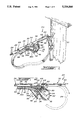
- FIG. 1 is a perspective view of a cable clamp according to a preferred embodiment of the invention, as seen holding a multi-wire cable suspended from a pole;
- FIGS. 2, 3 and 4 are side elevation views showing how the cable is inserted inside the clamp and retained in clamping engaging therein;
- FIG. 5 is a top plan view of the cable clamp
- FIG. 6 is a side elevation view showing the other side of the cable clamp
- FIG. 7 is a sectional view taken along line 7--7 of FIG. 6;
- FIG. 8 is another sectional view taken along line 8--8 of FIG. 5;
- FIG. 9 is a further sectional view taken along line 9--9 of FIG. 2;
- FIG. 10 is a perspective view of the wedge member of the cable clamp illustrated in FIG. 1;
- FIG. 11 is a fragmentary sectional view of a cable clamp according to another preferred embodiment of the invention, adapted for clamping a cable of circular cross-section;
- FIG. 12 is a fragmentary top plan view illustrating the hooking end of a cable clamp according to a further preferred embodiment of the invention.
- FIG. 13 is a fragmentary sideview of the embodiment illustrated in FIG. 12;
- FIG. 14 is a fragmentary top plan view illustrating the hooking end of a cable clamp according to yet another preferred embodiment of the invention.
- FIG. 15 is a fragmentary sideview of the embodiment illustrated in FIG. 14.
- FIG. 16 is a fragmentary sectional view taken along line 16--16 of FIG. 14.
- FIG. 1 a cable clamp which is generally designated by reference numeral 20 and seen hooked to a pole 22, holding a multi-wire cable 24 suspended therefrom.
- the cable 24 is typically a telephone aerial cable of rectangular cross-section, which comprises a plurality of longitudinal extending wires 26 covered with a sheath 28 of plastic material.
- the cable clamp 20 comprises two main components: a shell member 30 and a movable wedge member 32 mounted inside the shell member 30.
- the shell member 30 includes a planar base wall 34 and upper and lower elongated walls 36,38 extending at right angle to the base wall 34 and in opposed spaced-apart relation to one another to define at one end a mouth opening 40 for the passage of the cable 24.
- the lower wall 38 has a first wall portion 38a extending parallel to the upper wall 36 and defining together with the walls 34 and 36 an elongated throat passage 42 adjacent the mouth opening 40, and a second wall portion 38b disposed at an angle of about 50° relative to the first wall portion 38a.
- the wall 36 and wall portion 38b have respective elongated inner abutment surfaces 44 and 46 against which cable portions 24a and 24b are adapted to bear.
- the abutment surfaces 44 and 46 are disposed in opposed, spaced-apart facing relationship to one another and extend along respective longitudinal axes which intersect one another at an angle of about 50°.
- a first guide flange 48 extends along the side edge of upper wall 36 and parallel to the base wall 34, the flange 48 being substantially coextensive with the abutment surface 44 and defining together with the walls 34,36 a channel 50 for receiving the cable portion 24a.
- a second guide flange 52 extends along the side edge of wall portion 38b and parallel to the base wall 34, the flange 52 being also substantially coextensive with the abutment surface 46 and defining together the wall 34 and wall portion 38b a channel 54 for receiving the cable portion 24b. Both channels 50 and 54 merge into the throat passage 42.
- a guide tab 56 extends from the side edge of wall 36 and parallel to the base wall 34 for guiding the cable 24 through the mouth opening 40.
- a convexly curved protrusion 58 extends from the upper wall 36 and defines a corresponding recess 60 in the abutment surface 44, as best shown in FIG. 8.
- the recess 60 has a concavely curved, serrated surface 62.
- the wall 36 is extended rearwardly along the longitudinal axis thereof to define an elongate hooking member 64.
- the hooking member 64 is integral with the wall 36 and is formed with a loophole 66 for engaging a hook 68 or other similar fastener.
- the base wall 34 of the shell member 30 is provided with a plurality of spaced-apart reinforcing ribs which are formed by punching, as best shown in FIGS. 5-7.
- the wedge member 32 has a lead end 72 and comprises an elongated peripheral wall 74 having first and second wall portions 74a and 74b converging towards the lead end 72, and a third curved wall portion 74c intermediate the wall portions 74a and 74b, as best shown in FIG. 10.
- the wall portions 74a and 74b extend along respective longitudinal axes which intersect one another at an angle of about 50°.
- the wall portions 74a, 74b and 74c define outer surface portions 76a, 76b and 76c, respectively; as shown, the surface portions 76c, 76b and 76c are serrated.
- a planar sidewall 78 extend inwardly from one side edge of the peripheral wall 74, substantially parallel to and adjacent the base wall 34 of the shell member 30.
- a guide flange 80 extends continuously along the other side edge of the peripheral wall 74.
- the outer surface portions 76a and 76b of the wedge member 32 cooperate with the inner surfaces 44 and 46, respectively, of the shell member 30 to wedge the cable portions 24a and 24b.
- the wedge member 32 is slidably mounted on the base wall 34 of the shell member 30 for sliding movement between the non-wedging position illustrated in FIG. 2 and the wedging position illustrated in FIG. 4.
- the base wall 34 is provided with an outwardly projecting tongue 82 which extends through a slot 84 formed in the sidewall 78 of the wedge member 32.
- the tongue 82 is inclined relative to the base wall 34 and has an end portion 86 which extends parallel to the sidewall 78 and is in sliding contact engagement therewith.
- the tongue 82 and slot 84 thus serve to guide the wedge member 32 during movement thereof between the wedging and non-wedging positions, while retaining the wedge member 32 mounted on the base wall 34 of the shell member 30. Movement of the wedge member 32 is limited by the length of the slot 82.
- the cable 24 is passed through the mouth opening 40 and throat passage 42 and into the channel 50 so as to extend rearwardly beyond the wedge member 32, as shown in FIG. 2.
- the cable 24 is then looped about the wedge member 32 so as to extend in a direction towards the mouth opening 40, and passed into the channel 54 and again through the throat passage 42 to exit through the opening 40, as shown in FIG. 3.
- the loop portion 24c engages the outer surface portion 76c of wedge member 32 to thereby move the wedge member 32 from the non-wedging position illustrated in FIG. 3 to the wedging position illustrated in FIG.
- the recess 60 thus defines a cable arresting means preventing longitudinal displacement of the cable 24 when the wedge member 32 is in the wedging position.
- the slip-preventing serrations which are formed in the surface 62 as well as in the surface portions 76a, 76b and 76c also contribute to prevent longitudinal displacement of the cable 24.
- the flanges 48, 52 and 80 prevent lateral displacement of the cable.
- mouth opening 40 and throat passage 42 together with the passages defined between the flanges 48,52 and the wedge member 32 in the non-wedging position define a Y-shaped side opening, it is also possible to first form a loop with the cable 24 and then insert the loop sideways directly into the side opening, around the wedge member 32.
- FIG. 11 illustrates a cable clamp 20' according to another embodiment of the invention, which is adapted to clamp a cable 24' of circular cross-section, such as a coaxial TV cable.
- the upper wall 36' which extends transversely of the base wall 34' of shell member 30' has a semi-circular cross-section.
- the peripheral wall 74' which extends transversely of the sidewall 78' of wedge member 32' has a semi-circular cross-section.
- the walls 36' and 74' cooperate to clampingly engage the cable 24' received therebetween.
- the lower wall of shell member 30' has the same cross-section as the upper wall 36'.
- a metallic wire 164 which is bent to define a hooking loop, as shown in FIGS. 12 and 13.
- the legs 186,186' of the bent wire 164 are connected to an extension 188 which projects rearwardly from the shell member 130 and extends along the longitudinal axis of the upper wall 136.
- Leg 186 which is shorter than leg 186' is fixedly connected to the extension 188, whereas leg 186' is releasably connected.
- the legs 186,186' have right angled end portions 190,190' provided with beaded heads 192,192'.
- leg 186 extends through the restricted passage of a keyhole-shaped slot 194, where it is retained captive by material punched to form a pair of opposed stop lugs partially closing the passage, as shown in FIG. 12.
- the end portion 190' of leg 186' also extends through the restricted passage of a keyhole-shaped slot 196, but may be removed by passing the beaded head 192' through the eye portion of the slot 196, as shown in FIG. 12.
- Such an arrangement enables the leg 186' to be disconnected from the extension 188 for passage through the opening of an eyebolt or like fastener.
- reference numeral 134 designates the base wall of shell member 130 and reference numeral 148 the flange of wall 136.
- a metallic wire 264 is also bent to define a hooking loop, but the legs 286,286' of the bent wire are both fixedly secured to the extension 288 which projects rearwarly from the shell member 230 and extends along the longitudinal axis of the upper wall 236.
- the legs 286,286' extend in close parallel relation to one another and have end portions 290,290' extending through an aperture 292 formed in the extension 288.
- Both end portions 290,290' are bent backwards so as to extend through a cavity 294 defined by a punched bridge portion 296. The end portions 290,290' are thus retained captive in the cavity 294 by the bridge portion 296.
- leg 286,286' are also secured to the extension 288 by a retention collar 298.
- a U-shaped slit 300 is formed in the extension 288 to provide a tongue 302 which may be bent upwardly as shown in broken line in FIG. 25, to enlarge the aperture 292 for permitting passage of the end portions 290,290' of legs 286,286'.
- reference numeral 234 designates the base wall of shell member 230 and reference numeral 248 the flange of wall 236.
Landscapes
- Installation Of Indoor Wiring (AREA)
- Supports For Pipes And Cables (AREA)
- Clamps And Clips (AREA)
Priority Applications (2)
| Application Number | Priority Date | Filing Date | Title |
|---|---|---|---|
| CA002070887A CA2070887C (fr) | 1992-06-09 | 1992-06-09 | Serre-cable a clavette en boucle |
| US07/904,147 US5336846A (en) | 1992-06-09 | 1992-06-25 | Cable clamp having loop-forming wedge |
Applications Claiming Priority (2)
| Application Number | Priority Date | Filing Date | Title |
|---|---|---|---|
| CA002070887A CA2070887C (fr) | 1992-06-09 | 1992-06-09 | Serre-cable a clavette en boucle |
| US07/904,147 US5336846A (en) | 1992-06-09 | 1992-06-25 | Cable clamp having loop-forming wedge |
Publications (1)
| Publication Number | Publication Date |
|---|---|
| US5336846A true US5336846A (en) | 1994-08-09 |
Family
ID=25675200
Family Applications (1)
| Application Number | Title | Priority Date | Filing Date |
|---|---|---|---|
| US07/904,147 Expired - Lifetime US5336846A (en) | 1992-06-09 | 1992-06-25 | Cable clamp having loop-forming wedge |
Country Status (2)
| Country | Link |
|---|---|
| US (1) | US5336846A (fr) |
| CA (1) | CA2070887C (fr) |
Cited By (25)
| Publication number | Priority date | Publication date | Assignee | Title |
|---|---|---|---|---|
| US5639049A (en) * | 1996-05-08 | 1997-06-17 | Jennings; Gilbert M. | Compact cable clip for retainment of cables and tubing |
| US5869785A (en) * | 1997-06-10 | 1999-02-09 | Antec Corporation | Wire clamp with parallel gripping action |
| US6249938B1 (en) | 1999-07-28 | 2001-06-26 | Murray, Inc. | Cable length adjustment device |
| US6256841B1 (en) | 1998-12-31 | 2001-07-10 | Otis Elevator Company | Wedge clamp type termination for elevator tension member |
| FR2844111A1 (fr) * | 2002-09-03 | 2004-03-05 | Telenco Telecomm Engineering C | Pince d'ancrage pour cable de telecommunication |
| KR100445984B1 (ko) * | 2002-05-10 | 2004-08-25 | 이치우 | 케이블 클램프 |
| US6789295B1 (en) * | 1998-08-21 | 2004-09-14 | Amicus Trade Ab | Clamp apparatus |
| US20040195556A1 (en) * | 2001-08-01 | 2004-10-07 | Facey Hugh David | Wire or like connectors/tensioners |
| US6832414B2 (en) | 2002-11-30 | 2004-12-21 | Bellsouth Intellectual Property Corporation | Apparatus and method for clamping cable |
| US6898827B1 (en) | 2003-08-06 | 2005-05-31 | The Crosby Group, Inc. | Wedge socket with actuator assembly |
| US20050218269A1 (en) * | 2004-04-01 | 2005-10-06 | Senior Industries, Inc. | Clamp |
| US20050238311A1 (en) * | 2004-04-22 | 2005-10-27 | Forrester Joseph H | Support fixture and method for supporting subscriber specific fiber optic drop wire |
| AT500454A1 (de) * | 1999-09-16 | 2005-12-15 | Ensto Sekko Oy | Endklemme für ein isoliertes oberirdisches kabel |
| US20060275010A1 (en) * | 2004-04-22 | 2006-12-07 | Joseph Forrester | Support Fixture and Method for Supporting Subscriber Specific Fiber Optic Drop Wire |
| EP1746061A1 (fr) * | 2005-07-22 | 2007-01-24 | Inventio Ag | Fixation de fin de courroie pour attacher la courroie d'un ascenseur |
| US20070034454A1 (en) * | 2005-07-22 | 2007-02-15 | Inventio Ag | Support Means End Connection for Fastening an End of a Support Means in an Elevator Installation, an Elevator Installation with a Support Means End Connection, and a Method for Fastening an End of a Support Means in an Elevator Installation |
| USD538621S1 (en) * | 2005-09-28 | 2007-03-20 | Anton Van Es | Wedge clamp |
| US20090317180A1 (en) * | 2008-06-24 | 2009-12-24 | Esco Corporation | Wedge and Socket Assembly |
| US20100037436A1 (en) * | 2008-08-13 | 2010-02-18 | Smith Rory S | Rope Termination Device |
| US9120656B2 (en) | 2012-06-14 | 2015-09-01 | Warn Industries, Inc. | Rope anchor for a winch |
| US20150266636A1 (en) * | 2014-03-24 | 2015-09-24 | Ideal Industries, Inc. | Cable lacing tie devices and methods of using the same |
| US10228044B2 (en) * | 2015-10-29 | 2019-03-12 | Factor 55, Llc | Splicer thimble for rope |
| US10677316B2 (en) | 2015-10-29 | 2020-06-09 | Factor 55, Llc | Clevis mount thimble |
| CN112260195A (zh) * | 2020-09-23 | 2021-01-22 | 安徽华希电力科技有限公司 | 一种可调整安装角度以适应电缆头的三芯电缆卡具装置 |
| US20230249014A1 (en) * | 2020-06-12 | 2023-08-10 | Latchways Plc | Self-Tightening Cable Clamp |
Citations (12)
| Publication number | Priority date | Publication date | Assignee | Title |
|---|---|---|---|---|
| US421120A (en) * | 1890-02-11 | John j | ||
| FR357674A (fr) * | 1905-09-12 | 1906-01-09 | Charles Henri Auriol | Attache pour cables |
| FR492439A (fr) * | 1918-10-22 | 1919-07-08 | Henri Amouroux | Dispositif de jonction des fils et cables métalliques aux tendeurs, crochets et autres organes d'attache |
| US1380800A (en) * | 1921-06-07 | Worth | ||
| US1759591A (en) * | 1928-07-25 | 1930-05-20 | Newhall Henry B Corp | Drop-wire support |
| FR1108346A (fr) * | 1953-09-28 | 1956-01-11 | Gutehoffnungshuette Sterkrade | Attache de câble à cosse, en particulier pour installations d'extraction en puits de mine |
| US2781212A (en) * | 1952-11-05 | 1957-02-12 | Reliable Electric Co | Wire supporting device |
| US3905711A (en) * | 1974-10-31 | 1975-09-16 | Marion Power Shovel Co | Cable connecting assembly |
| US3960461A (en) * | 1975-04-07 | 1976-06-01 | Isaac Sachs | Drop wire clamps |
| US4362288A (en) * | 1980-06-27 | 1982-12-07 | Herman Allen | Shock-absorbing cable anchor for mobile equipment |
| US4407471A (en) * | 1980-12-17 | 1983-10-04 | Dr. Franz & Rutenbeck | Clamping device for self-supporting electric cables |
| SU1153147A1 (en) * | 1983-07-22 | 1985-04-30 | Zverev Aleksandr | Clip for rope |
-
1992
- 1992-06-09 CA CA002070887A patent/CA2070887C/fr not_active Expired - Fee Related
- 1992-06-25 US US07/904,147 patent/US5336846A/en not_active Expired - Lifetime
Patent Citations (12)
| Publication number | Priority date | Publication date | Assignee | Title |
|---|---|---|---|---|
| US421120A (en) * | 1890-02-11 | John j | ||
| US1380800A (en) * | 1921-06-07 | Worth | ||
| FR357674A (fr) * | 1905-09-12 | 1906-01-09 | Charles Henri Auriol | Attache pour cables |
| FR492439A (fr) * | 1918-10-22 | 1919-07-08 | Henri Amouroux | Dispositif de jonction des fils et cables métalliques aux tendeurs, crochets et autres organes d'attache |
| US1759591A (en) * | 1928-07-25 | 1930-05-20 | Newhall Henry B Corp | Drop-wire support |
| US2781212A (en) * | 1952-11-05 | 1957-02-12 | Reliable Electric Co | Wire supporting device |
| FR1108346A (fr) * | 1953-09-28 | 1956-01-11 | Gutehoffnungshuette Sterkrade | Attache de câble à cosse, en particulier pour installations d'extraction en puits de mine |
| US3905711A (en) * | 1974-10-31 | 1975-09-16 | Marion Power Shovel Co | Cable connecting assembly |
| US3960461A (en) * | 1975-04-07 | 1976-06-01 | Isaac Sachs | Drop wire clamps |
| US4362288A (en) * | 1980-06-27 | 1982-12-07 | Herman Allen | Shock-absorbing cable anchor for mobile equipment |
| US4407471A (en) * | 1980-12-17 | 1983-10-04 | Dr. Franz & Rutenbeck | Clamping device for self-supporting electric cables |
| SU1153147A1 (en) * | 1983-07-22 | 1985-04-30 | Zverev Aleksandr | Clip for rope |
Cited By (36)
| Publication number | Priority date | Publication date | Assignee | Title |
|---|---|---|---|---|
| US5639049A (en) * | 1996-05-08 | 1997-06-17 | Jennings; Gilbert M. | Compact cable clip for retainment of cables and tubing |
| US5869785A (en) * | 1997-06-10 | 1999-02-09 | Antec Corporation | Wire clamp with parallel gripping action |
| US6789295B1 (en) * | 1998-08-21 | 2004-09-14 | Amicus Trade Ab | Clamp apparatus |
| US6256841B1 (en) | 1998-12-31 | 2001-07-10 | Otis Elevator Company | Wedge clamp type termination for elevator tension member |
| US6357085B2 (en) | 1998-12-31 | 2002-03-19 | Otis Elevator Company | Wedge clamp type termination for elevator tension member |
| USRE47035E1 (en) | 1998-12-31 | 2018-09-11 | Otis Elevator Company | Wedge clamp type termination for elevator tension member |
| US6249938B1 (en) | 1999-07-28 | 2001-06-26 | Murray, Inc. | Cable length adjustment device |
| AT500454B1 (de) * | 1999-09-16 | 2006-05-15 | Ensto Sekko Oy | Endklemme für ein isoliertes oberirdisches kabel |
| RU2597078C9 (ru) * | 1999-09-16 | 2016-11-20 | Энсто Финланд Ой | Натяжной зажим для изолированного воздушного кабеля |
| RU2597078C2 (ru) * | 1999-09-16 | 2016-09-10 | Энсто Финланд Ой | Натяжной зажим для изолированного воздушного кабеля |
| AT500454A1 (de) * | 1999-09-16 | 2005-12-15 | Ensto Sekko Oy | Endklemme für ein isoliertes oberirdisches kabel |
| US20040195556A1 (en) * | 2001-08-01 | 2004-10-07 | Facey Hugh David | Wire or like connectors/tensioners |
| KR100445984B1 (ko) * | 2002-05-10 | 2004-08-25 | 이치우 | 케이블 클램프 |
| FR2844111A1 (fr) * | 2002-09-03 | 2004-03-05 | Telenco Telecomm Engineering C | Pince d'ancrage pour cable de telecommunication |
| US6832414B2 (en) | 2002-11-30 | 2004-12-21 | Bellsouth Intellectual Property Corporation | Apparatus and method for clamping cable |
| US6898827B1 (en) | 2003-08-06 | 2005-05-31 | The Crosby Group, Inc. | Wedge socket with actuator assembly |
| US20050218269A1 (en) * | 2004-04-01 | 2005-10-06 | Senior Industries, Inc. | Clamp |
| US7234669B2 (en) * | 2004-04-01 | 2007-06-26 | Senior Industries, Inc. | Clamp |
| US20060275010A1 (en) * | 2004-04-22 | 2006-12-07 | Joseph Forrester | Support Fixture and Method for Supporting Subscriber Specific Fiber Optic Drop Wire |
| US20050238311A1 (en) * | 2004-04-22 | 2005-10-27 | Forrester Joseph H | Support fixture and method for supporting subscriber specific fiber optic drop wire |
| US7578035B2 (en) | 2005-07-22 | 2009-08-25 | Inventio Ag | Support means end connection for fastening an end of a support means in an elevator installation, an elevator installation with a support means end connection, and a method for fastening an end of a support means in an elevator installation |
| US20070034454A1 (en) * | 2005-07-22 | 2007-02-15 | Inventio Ag | Support Means End Connection for Fastening an End of a Support Means in an Elevator Installation, an Elevator Installation with a Support Means End Connection, and a Method for Fastening an End of a Support Means in an Elevator Installation |
| EP1746061A1 (fr) * | 2005-07-22 | 2007-01-24 | Inventio Ag | Fixation de fin de courroie pour attacher la courroie d'un ascenseur |
| USD538621S1 (en) * | 2005-09-28 | 2007-03-20 | Anton Van Es | Wedge clamp |
| US8381364B2 (en) | 2008-06-24 | 2013-02-26 | Esco Corporation | Wedge and socket assembly |
| US20090317180A1 (en) * | 2008-06-24 | 2009-12-24 | Esco Corporation | Wedge and Socket Assembly |
| US8096024B2 (en) | 2008-08-13 | 2012-01-17 | Thyssenkrupp Elevator Capital Corporation | Rope termination device |
| US20100037436A1 (en) * | 2008-08-13 | 2010-02-18 | Smith Rory S | Rope Termination Device |
| US9120656B2 (en) | 2012-06-14 | 2015-09-01 | Warn Industries, Inc. | Rope anchor for a winch |
| US20150266636A1 (en) * | 2014-03-24 | 2015-09-24 | Ideal Industries, Inc. | Cable lacing tie devices and methods of using the same |
| US9682806B2 (en) * | 2014-03-24 | 2017-06-20 | Ideal Industries, Inc. | Cable lacing tie devices and methods of using the same |
| RU2671773C2 (ru) * | 2014-03-24 | 2018-11-06 | Идеал Индастриз, Инк. | Кабельные обвязочные стягивающие устройства и способы их использования |
| US10228044B2 (en) * | 2015-10-29 | 2019-03-12 | Factor 55, Llc | Splicer thimble for rope |
| US10677316B2 (en) | 2015-10-29 | 2020-06-09 | Factor 55, Llc | Clevis mount thimble |
| US20230249014A1 (en) * | 2020-06-12 | 2023-08-10 | Latchways Plc | Self-Tightening Cable Clamp |
| CN112260195A (zh) * | 2020-09-23 | 2021-01-22 | 安徽华希电力科技有限公司 | 一种可调整安装角度以适应电缆头的三芯电缆卡具装置 |
Also Published As
| Publication number | Publication date |
|---|---|
| CA2070887A1 (fr) | 1993-12-10 |
| CA2070887C (fr) | 1995-04-25 |
Similar Documents
| Publication | Publication Date | Title |
|---|---|---|
| US5336846A (en) | Cable clamp having loop-forming wedge | |
| US6094783A (en) | Rope clamp | |
| US6003208A (en) | Parallel entry tie | |
| US4191334A (en) | Cable tie | |
| US6012204A (en) | Fitting for attachment to a rope | |
| US4432121A (en) | Safety hook or elastic fastening and securing cables of the sandow type | |
| US5033169A (en) | Rope fastener | |
| US10795108B2 (en) | Spring assist cable clamps | |
| JP4257288B2 (ja) | 長尺部材用クランプ | |
| JPH05118471A (ja) | ケーブル締結部材 | |
| US5890265A (en) | Parallel entry tie | |
| US9958089B2 (en) | Lashing support spacer tie | |
| US6355887B1 (en) | Cable support | |
| US6763553B2 (en) | Low profile latchable tie | |
| US5513421A (en) | Cable tie having an improved strap locking device | |
| US8650725B1 (en) | System and method for securing a flexible panel | |
| US6526628B1 (en) | Low thread force cable tie with locking device that pierces strap | |
| EP0971845A1 (fr) | Attache de cable en ligne | |
| US5596791A (en) | Rope clamp | |
| USRE31689E (en) | Cable tie | |
| US4477948A (en) | Dead-end messenger wire holder | |
| CA3131047C (fr) | Dispositif et methode d'attache de lacet rapide | |
| US12401183B2 (en) | Single person wedge clamp | |
| US5689911A (en) | Easy tie fish hook | |
| JP2842392B2 (ja) | 低圧引込線用絶縁クランプ |
Legal Events
| Date | Code | Title | Description |
|---|---|---|---|
| STCF | Information on status: patent grant |
Free format text: PATENTED CASE |
|
| AS | Assignment |
Owner name: DIAMOND COMMUNICATION PRODUCTS,INC., NEW JERSEY Free format text: ASSIGNMENT OF ASSIGNORS INTEREST;ASSIGNOR:SACHS,ISAAC;REEL/FRAME:007603/0411 Effective date: 19950817 |
|
| FEPP | Fee payment procedure |
Free format text: PAYOR NUMBER ASSIGNED (ORIGINAL EVENT CODE: ASPN); ENTITY STATUS OF PATENT OWNER: LARGE ENTITY |
|
| FPAY | Fee payment |
Year of fee payment: 4 |
|
| AS | Assignment |
Owner name: THOMAS & BETTS INTERNATIONAL, INC., NEVADA Free format text: ASSIGNMENT OF ASSIGNORS INTEREST;ASSIGNOR:DIAMOND COMMUNICATION PRODUCTS, INC.;REEL/FRAME:009423/0208 Effective date: 19980623 |
|
| FEPP | Fee payment procedure |
Free format text: PAT HOLDER NO LONGER CLAIMS SMALL ENTITY STATUS, ENTITY STATUS SET TO UNDISCOUNTED (ORIGINAL EVENT CODE: STOL); ENTITY STATUS OF PATENT OWNER: LARGE ENTITY |
|
| FEPP | Fee payment procedure |
Free format text: PAYER NUMBER DE-ASSIGNED (ORIGINAL EVENT CODE: RMPN); ENTITY STATUS OF PATENT OWNER: LARGE ENTITY Free format text: PAYOR NUMBER ASSIGNED (ORIGINAL EVENT CODE: ASPN); ENTITY STATUS OF PATENT OWNER: LARGE ENTITY |
|
| FPAY | Fee payment |
Year of fee payment: 8 |
|
| REMI | Maintenance fee reminder mailed | ||
| FEPP | Fee payment procedure |
Free format text: ENTITY STATUS SET TO UNDISCOUNTED (ORIGINAL EVENT CODE: BIG.); ENTITY STATUS OF PATENT OWNER: LARGE ENTITY |
|
| FPAY | Fee payment |
Year of fee payment: 12 |
|
| AS | Assignment |
Owner name: BELDEN INC., MISSOURI Free format text: ASSIGNMENT OF ASSIGNORS INTEREST;ASSIGNORS:THOMAS & BETTS CORPORATION;THOMAS & BETTS INTERNATIONAL, INC.;THOMAS & BETTS LIMITED;REEL/FRAME:026133/0421 Effective date: 20101119 |