US5361995A - Automatic product feed and method for controlling a milling roller mill - Google Patents
Automatic product feed and method for controlling a milling roller mill Download PDFInfo
- Publication number
- US5361995A US5361995A US07/910,187 US91018792A US5361995A US 5361995 A US5361995 A US 5361995A US 91018792 A US91018792 A US 91018792A US 5361995 A US5361995 A US 5361995A
- Authority
- US
- United States
- Prior art keywords
- roller mill
- feed
- product
- analog signal
- signal
- Prior art date
- Legal status (The legal status is an assumption and is not a legal conclusion. Google has not performed a legal analysis and makes no representation as to the accuracy of the status listed.)
- Expired - Fee Related
Links
- 238000000034 method Methods 0.000 title claims abstract description 14
- 238000003801 milling Methods 0.000 title claims abstract description 11
- 238000000227 grinding Methods 0.000 claims abstract description 41
- 230000001105 regulatory effect Effects 0.000 claims abstract description 28
- 230000001276 controlling effect Effects 0.000 claims abstract description 11
- 239000000523 sample Substances 0.000 claims abstract description 5
- 238000010276 construction Methods 0.000 description 9
- 238000005516 engineering process Methods 0.000 description 6
- 230000005540 biological transmission Effects 0.000 description 3
- 238000006243 chemical reaction Methods 0.000 description 3
- 238000013016 damping Methods 0.000 description 2
- 230000000087 stabilizing effect Effects 0.000 description 2
- 241000191291 Abies alba Species 0.000 description 1
- 206010015535 Euphoric mood Diseases 0.000 description 1
- 230000002743 euphoric effect Effects 0.000 description 1
- 230000002349 favourable effect Effects 0.000 description 1
- 235000013312 flour Nutrition 0.000 description 1
- 238000009472 formulation Methods 0.000 description 1
- 238000009434 installation Methods 0.000 description 1
- 230000010354 integration Effects 0.000 description 1
- 238000012423 maintenance Methods 0.000 description 1
- 239000000203 mixture Substances 0.000 description 1
- 238000012544 monitoring process Methods 0.000 description 1
- 230000003287 optical effect Effects 0.000 description 1
- 230000008092 positive effect Effects 0.000 description 1
Images



Classifications
-
- B—PERFORMING OPERATIONS; TRANSPORTING
- B02—CRUSHING, PULVERISING, OR DISINTEGRATING; PREPARATORY TREATMENT OF GRAIN FOR MILLING
- B02C—CRUSHING, PULVERISING, OR DISINTEGRATING IN GENERAL; MILLING GRAIN
- B02C4/00—Crushing or disintegrating by roller mills
- B02C4/28—Details
- B02C4/32—Adjusting, applying pressure to, or controlling the distance between, milling members
-
- B—PERFORMING OPERATIONS; TRANSPORTING
- B02—CRUSHING, PULVERISING, OR DISINTEGRATING; PREPARATORY TREATMENT OF GRAIN FOR MILLING
- B02C—CRUSHING, PULVERISING, OR DISINTEGRATING IN GENERAL; MILLING GRAIN
- B02C4/00—Crushing or disintegrating by roller mills
- B02C4/28—Details
- B02C4/286—Feeding devices
Definitions
- the invention is directed to an automatic product feed for a milling roller mill having a mechanical sensor, a product feed device with adjustable drive means for the feed rolls, as well as engaging and disengaging means for the grinding rolls, and to a method for controlling the grinding in a milling roller mill.
- the amount of product flowing into the roller mill must be processed within a bandwidth and metered to the grinding rolls while compensating for temporary feed fluctuations as far as possible;
- the product feed to the grinding rolls must be stopped with minimum delay and the grinding rolls must be moved apart simultaneously.
- the grinding process is acknowledged as the core of every mill. Therefore, the quality of the grinding is influenced by a number of parameters. Special importance is attached to the regulation of the product feed to the grinding rolls and to trouble-free operation of the elements required for this.
- the degree of automation in a modern mill has already reached a particularly high level. A further increase in automation is demanded, not least of all, to ensure quality, at least to the extent that the parameters already presently influenced by hardware technology can be exploited to achieve even greater perfection so as to enable easier access through human intervention and management of the process.
- the device according to the invention is characterized in that it includes a first mechanical signal transmitter for a digital signal and a second mechanical signal transmitter for an analog signal.
- the novel invention allows a large number of particularly preferred constructions.
- the speed of the feed roll can be regulated via the analog signal and engagement and disengagement can be controlled via the digital signal.
- This division has the particular advantage that practice-related adjustments can be implemented independently of the regulation of the product feed and engagement and disengagement.
- Each function can be comprehended and supervised in itself.
- the drive means or a drive motor for the feed roll can be regulated in a continuous manner by the analog signal via an electrical converter unit.
- the analog signal is associated with the regulation of a product feed slide and the digital signal is associated with the engagement and disengagement.
- the regulation of the product feed slide can be effected corresponding to EP-PS No. 38 054.
- the mechanically movable sensor is preferably constructed, in a manner known per se, as a probe (e.g. christmas tree or perforated plate) extending in the direction of the product flow to be moved accompanied by spring tension, and the signal transmitter is constructed as a contact element moved by the sensor.
- a contact element, as signal transmitter for the analog signal or for the digital signal is associated with the probe in each instance, preferably at an outer end of the roller mill.
- a proximity switch for converting the mechanical signal into an analog electrical signal is associated with the signal transmitter for the analog signal, and a contact switch of an electrical valve for controlling the engagement and disengagement can be associated with the signal transmitter for the digital signal.
- a voltage transformer unit and a current transformer unit are directly associated with the signal transmitter for the analog signal and integrated in the roller mill.
- a frequency converter unit for regulating at least two, or a plurality of, feed rolls is preferably arranged at a distance from the roller mill.
- the drive motor is flanged directly on a gear unit for reversing the direction of rotation of the feed roll as well as of a distributing roll arranged parallel thereto.
- the rotational direction reversing gear unit has a reduction gear ratio of 1:5 to 1:20, preferably approximately 1:10, and the reduction and reversing gear unit can be formed from only three pairs of toothed wheels.
- an adjusting gear unit and a control unit for selecting different speed stages of the feed rolls, and the analog signal for regulating a product feed slide are associated with the drive motor and the engagement and disengagement is controlled via the digital signal.
- the invention is further directed to an automatic product feed for a milling roller mill with a mechanical sensor, a product feed device and means for regulating the product feed, wherein an analog signal can be generated via the sensor and a mechanical signal transmitter and further a control and storage unit is associated with the automatic product feed for different positions of an adjusting device.
- either the opening position of a feed segment is regulated via the analog signal corresponding to the amount of product fed to the roller mill and various speed stages of the feed roll are adjusted via the control and feed unit, or the speed of the feed rolls is regulated via the analog signal corresponding to the amount of product fed to the roller mill and various positions of a feed segment are adjusted via the control and storage unit.
- a digital signal can be generated from the analog signal, e.g. via limiting value switches, and the engagement and disengagement can be controlled by means of this digital signal.
- the novel invention allows the use of a control unit and storage and computing means in coordination with a control signal for adjusting the grinding gap according to a program which can be determined beforehand.
- the invention is further directed to a novel method for controlling the grinding of a milling roller mill which includes an adjusting device and an engaging and disengaging arrangement for the grinding rolls and a product feed to the grinding rolls which is regulated via a product flow sensor, which method is characterized in that an analog signal is generated via a mechanical sensor which regulates as a function of the amount of product fed to the roller mill, and further at least one independently adjustable digital signal is generated which controls either the engagement and disengagement of the grinding rolls or various basic adjustments of the product feed as a function of overriding parameters (mill output, product quality).
- the novel invention is the first to show that the generation of an analog signal and a digital signal which can be adjusted as a function of the latter permits the greatest possible freedom in selecting the manner in which the grinding is influenced and optimal grinding conditions are accordingly made possible for the first time for every case of application via the parameters involved in this application.
- every function to the lowest possible level can now be ensured autonomously using simple, inexpensive means.
- two digital signals are generated, wherein a first digital signal from the mechanical sensor controls the engagement and disengagement of the grinding rolls as a function of the product flow and a second digital signal generated by an independent control unit determines basic adjustments of the product feed.
- a determined rate of rotation for the feed roll can be preselected or adjusted at any time in the event of a change of product. Or a basic adjustment can be selected, or adjusted when the product is changed, for the segment or the metering gap.
- the product feed is regulated in every case autonomously or automatically via the analog signal generated by the mechanical sensor.
- control unit contains storage and computing means and can be used in coordination with a control signal for the grinding gap adjustment according to a program which can be fixed beforehand.
- An optimal feed roll speed can be adjusted, depending on grinding conditions, in the regulation of the amount of product by regulating the segment approximately in accordance with EP-PS 38 054 via a pneumatic regulation of the metering gap.
- An optimal value can be adjusted for the metering gap by means of a digital signal of a control unit in regulating the product amount by means of regulating the feed roll speed according to DE-GM 86 14 505.
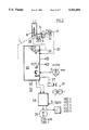
- FIG. 1 shows the basic elements for the grinding process in a milling roller mill in a schematic manner
- FIG. 2 shows an example with analog signal converter and digital contact switch
- FIG. 3 shows a special embodiment form of FIG. 1 with an electropneumatic valve for the engagement and disengagement of the grinding roll;
- FIG. 4 shows the generation of a mechanical-electrical converter unit with a rotary potentiometer in a schematic manner
- FIG. 5 shows a gear unit for the operation of the feed roll in a schematic manner
- FIG. 6 shows an example for regulating the feed by means of pneumatic regulation of a segment slide and for the control of various speed stages of the feed rolls;
- FIG. 7 shows a section through an 8-roll roller mill.
- FIG. 1 shows a milling roller mill 1 which is normally constructed in a two-fold manner, but only one half of which is shown.
- the supply of product is effected via a feed cylinder 2 in a product feed space 3 whose lower portion contains a distributing roll 4 and a feed roll 5 which can be made to rotate in the same direction via a gear unit 6 and drive means 7.
- a mechanical sensor 8 which is directly connected with a mechanical signal transmitter 9 in an articulated manner is located in the feed cylinder 2.
- the sensor 8 is held in its highest position by a tension field 10 in the absence of product flow.
- the flowing product presses the sensor 8 down and the signal transmitter 9 executes an analogous movement and transmits an analog signal, known per se, to a converter unit 11.
- a feed gap 12 is formed by a segment 13, a segment distributing device 14 being shown schematically in addition.
- FIG. 1 shows the two basic possibilities whereby either the speed of the feed roll 5 or the position of the feed segment 13 is influenced based upon the signal of the sensor 8 and a converter device (S/R) 15 via connections 16 and 16', respectively, shown in dashes.
- S/R converter device
- the product discharged in the feed roll 5 is fed to a grinding roll pair 18 corresponding to arrow 17.
- the grinding roll pair includes a fixed roll 19 and a loose roll 20.
- An engaging and disengaging arrangement 21 which is controlled via a control line 22 as a function of a control signal of the sensor 8 is associated with the loose roll 20.
- a flour gap adjusting device 23 is associated with the loose roll 20 and can be adjusted manually if necessary or via a motor 24 and an electronic storage/computer unit 25 as a function of either the specific grinding work or the quality of the ground product, or as a function of the product output of the roller mill 1.
- FIG. 2 shows a preferred construction of FIG. 1 with additional details with respect to the control and regulating elements.
- Two signal transmitters are shown, a signal transmitter 9 for the analog signal which is generated by the movement or position of a cam disk 30 and is transmitted via a control line to evaluating electronics 33 as an electric analog voltage signal by means of an analog signal converter 31; and a second signal transmitter 34 for a digital signal which is likewise transferred, via a contact switch 35 and a control line 36, to the evaluating electronics 33 from which a digital signal is transmitted via a control line 37 to the engaging and disengaging arrangement 21.
- the analog signal is converted in a frequency converter 38 directly for a drive motor 39 by which the speed of the feed roll 5 is regulated.
- FIG. 3 shows another construction possibility in a somewhat simplified construction.
- the analog signal can be controlled by the analog signal converter 31 via the digital signal for special operating positions.
- the digital signal directly controls an electropneumatic valve 40 which controls two pneumatic cylinders 41 and 42 for engaging and disengaging the grinding rolls.
- Various basic positions can be selected on site via a manual switch for desired operating states by supplying compressed air.
- FIG. 4 shows an even more simplified schematic view of the processing of the analog signal, in this case converted by a rotary potentiometer, and shows the conversion of a mechanical analog signal into an electrical analog signal.
- the tension spring 10 can be arranged in various positions and its tension varied via a tensioning screw 51 depending on the specific product quality and flow conditions.
- FIG. 5 shows the very simple reduction gear unit with a set of gear wheels for the feed roll 5 and for the distributing roll 4, respectively, and only one set of transmission rollers 60 and 61, respectively.
- the advantage of this construction consists in that the transmission required for the transmission from the feed roll to the distributing roll is simultaneously the reduction gearing from a drive motor to the feed roll.
- FIG. 6 shows another particularly advantageous construction for a completely self-regulating product feed via an analog signal and the possibility of a pre-adjustment of a feed roll speed stage by means of a motor, possibly by manual input 70 via a control unit 71.
- a switching lever 73 and automatic adjusting means 74 can be switched to one of the speed stages 1, 2, 3, 4 or 5 via a stage switching gear unit.
- the digital signal is initiated via the control unit according to external parameters.
- An analog signal is transmitted to the control unit simultaneously via an analog signal converter by the mechanical signal transmitter 9.
- this has the advantage that a corresponding position signal for monitoring tasks is utilized in the computer and various controls can be coordinated.
- the actual feed regulation is effected via the type of pneumatic regulation of the metering segment and metering gap 12 known from EP-PS 38 054.
- the engagement and disengagement is controlled by a digital signal modeled on the pneumatic analog signal and formed by a threshold value control valve 76.
- FIG. 7 shows the two halves of an 8-roll milling roller mill.
- Each sensor which is constructed in this case as a vertically disposed perforated plate, is associated with one vertical half, i.e. two roll pairs 19/20, 19'/20' arranged one above the other.
Landscapes
- Engineering & Computer Science (AREA)
- Food Science & Technology (AREA)
- Crushing And Grinding (AREA)
- Adjustment And Processing Of Grains (AREA)
- Disintegrating Or Milling (AREA)
- Constituent Portions Of Griding Lathes, Driving, Sensing And Control (AREA)
Priority Applications (1)
| Application Number | Priority Date | Filing Date | Title |
|---|---|---|---|
| US08/335,980 US5485965A (en) | 1990-12-12 | 1994-11-04 | Automatic product feed and method for controlling a milling roller mill |
Applications Claiming Priority (3)
| Application Number | Priority Date | Filing Date | Title |
|---|---|---|---|
| CH3931/90A CH682809A5 (de) | 1990-12-12 | 1990-12-12 | Produktspeiseautomatik, Verfahren zur Steuerung der Vermahlung eines Müllereiwalzenstuhles. |
| CH3931/90 | 1990-12-12 | ||
| PCT/CH1991/000248 WO1992010295A1 (de) | 1990-12-12 | 1991-12-05 | Produktspeiseautomatik und verfahren zur steuerung eines müllereiwalzenstuhles |
Related Child Applications (1)
| Application Number | Title | Priority Date | Filing Date |
|---|---|---|---|
| US08/335,980 Continuation US5485965A (en) | 1990-12-12 | 1994-11-04 | Automatic product feed and method for controlling a milling roller mill |
Publications (1)
| Publication Number | Publication Date |
|---|---|
| US5361995A true US5361995A (en) | 1994-11-08 |
Family
ID=4266577
Family Applications (2)
| Application Number | Title | Priority Date | Filing Date |
|---|---|---|---|
| US07/910,187 Expired - Fee Related US5361995A (en) | 1990-12-12 | 1991-12-05 | Automatic product feed and method for controlling a milling roller mill |
| US08/335,980 Expired - Fee Related US5485965A (en) | 1990-12-12 | 1994-11-04 | Automatic product feed and method for controlling a milling roller mill |
Family Applications After (1)
| Application Number | Title | Priority Date | Filing Date |
|---|---|---|---|
| US08/335,980 Expired - Fee Related US5485965A (en) | 1990-12-12 | 1994-11-04 | Automatic product feed and method for controlling a milling roller mill |
Country Status (10)
| Country | Link |
|---|---|
| US (2) | US5361995A (de) |
| EP (1) | EP0515596B1 (de) |
| JP (1) | JPH0832309B2 (de) |
| KR (1) | KR970001781B1 (de) |
| AT (1) | ATE114503T1 (de) |
| CH (1) | CH682809A5 (de) |
| DE (1) | DE59103700D1 (de) |
| ES (1) | ES2067959T3 (de) |
| RU (1) | RU2066564C1 (de) |
| WO (1) | WO1992010295A1 (de) |
Cited By (8)
| Publication number | Priority date | Publication date | Assignee | Title |
|---|---|---|---|---|
| US5485965A (en) * | 1990-12-12 | 1996-01-23 | Buehler Ag | Automatic product feed and method for controlling a milling roller mill |
| US5509612A (en) * | 1991-02-11 | 1996-04-23 | Gerteis; Paul | Process and device for the continuous shaping of particulate materials |
| DE19726551A1 (de) * | 1997-06-23 | 1998-12-24 | Buehler Ag | Speisesensorik |
| US20160067713A1 (en) * | 2013-04-23 | 2016-03-10 | Satake Corporation | Stock level detector for roll machine for milling |
| CN105536943A (zh) * | 2015-12-24 | 2016-05-04 | 山东理工大学 | 一种点连接式多仓管磨机胀肚检测装置及预胀肚调控方法 |
| WO2020106244A3 (en) * | 2018-07-30 | 2020-07-23 | Alapala Maki̇na Gida Sanayi̇ Ve Ti̇caret Anoni̇m Şi̇rketi̇ | A roller mill machine |
| CN113663770A (zh) * | 2021-08-23 | 2021-11-19 | 中粮工程装备(张家口)有限公司 | 一种磨粉机在线研磨监测系统及方法 |
| US11185867B2 (en) | 2018-05-25 | 2021-11-30 | Bühler AG | Distribution metering device for a roller mill, roller mill with such a distribution metering device, method for grinding grinding stock, and roller mill comprising a switching cabinet with a cooling system |
Families Citing this family (19)
| Publication number | Priority date | Publication date | Assignee | Title |
|---|---|---|---|---|
| DE4226182A1 (de) * | 1992-08-07 | 1994-02-10 | Kloeckner Humboldt Deutz Ag | Anlage und Verfahren zur Druckbehandlung körnigen Gutes |
| US5865382A (en) * | 1997-01-24 | 1999-02-02 | Beloit Technologies, Inc. | Protection system for a wood chip destructuring device |
| DE19722523A1 (de) * | 1997-05-30 | 1998-12-03 | Buehler Ag | Verfahren und Vorrichtung zur hydraulisch-elektrischen Spaltregelung |
| JP2003071314A (ja) * | 2001-08-31 | 2003-03-11 | Kobe Steel Ltd | 水熱養生設備および水熱養生造粒物の製造方法 |
| JP2004041984A (ja) * | 2002-07-15 | 2004-02-12 | Taiheiyo Cement Corp | 平板状物の破砕システム |
| JP4599492B2 (ja) * | 2003-12-09 | 2010-12-15 | 明治機械株式会社 | 穀物・種子・固形樹脂の製粉機 |
| WO2006115509A2 (en) | 2004-06-24 | 2006-11-02 | Novartis Vaccines And Diagnostics Inc. | Small molecule immunopotentiators and assays for their detection |
| DE102004052084B4 (de) * | 2004-10-26 | 2016-10-27 | Bühler AG | Walzwerk |
| DE102007006092A1 (de) * | 2007-02-07 | 2008-08-14 | Polysius Ag | Verfahren zur Zerkleinerung von Mahlgut mit einer Rollenmühle |
| CN102076418B (zh) | 2008-07-02 | 2014-04-09 | 布勒股份公司 | 生产面粉的方法、料床辊磨机和之字形分离器及其应用 |
| DE102008036784C5 (de) * | 2008-08-07 | 2013-06-20 | Thyssenkrupp Polysius Ag | Rollenmühle und Verfahren zur Zerkleinerung von Mahlgut |
| US8070081B2 (en) * | 2009-05-14 | 2011-12-06 | Wark Rickey E | Pressure monitor for pulverizer |
| JP5108855B2 (ja) * | 2009-10-23 | 2012-12-26 | 明治機械株式会社 | 穀物・種子・固形樹脂の製粉機 |
| US8544774B1 (en) * | 2012-04-20 | 2013-10-01 | Metso Minerals Industries, Inc. | Roller crusher, and method of protecting a roller crusher from uncrushable objects |
| CN105214825B (zh) * | 2015-10-27 | 2017-09-01 | 张荣斌 | 一种八辊式破碎机的自动控制系统及方法 |
| CN105562148B (zh) * | 2016-01-20 | 2018-01-16 | 福建安井食品股份有限公司 | 速冻后结块食品的滚轮压散装置 |
| CN107377092B (zh) * | 2017-08-17 | 2019-03-26 | 中国电子科技集团公司第十八研究所 | 一种粉料的辊压进料装置 |
| JP6876896B2 (ja) * | 2017-11-06 | 2021-05-26 | アイメックス株式会社 | 移動ロールの位置調整装置及び同装置を備えたロールミル |
| CN117561123A (zh) * | 2021-07-12 | 2024-02-13 | 布勒股份公司 | 进料水平控制系统和方法 |
Citations (2)
| Publication number | Priority date | Publication date | Assignee | Title |
|---|---|---|---|---|
| US4442980A (en) * | 1980-04-11 | 1984-04-17 | Bebruder Buhler AG. | Procedure and mechanism for the automatic control of a grinding mill roller carriage equipped with a regulated product feed |
| US4881689A (en) * | 1985-03-15 | 1989-11-21 | Gebrueder Buehler Ag | Method for setting the grinding rollers in roller frames of a flour milling plant, as well as flour milling plant for performing the method |
Family Cites Families (1)
| Publication number | Priority date | Publication date | Assignee | Title |
|---|---|---|---|---|
| CH682809A5 (de) * | 1990-12-12 | 1993-11-30 | Buehler Ag | Produktspeiseautomatik, Verfahren zur Steuerung der Vermahlung eines Müllereiwalzenstuhles. |
-
1990
- 1990-12-12 CH CH3931/90A patent/CH682809A5/de not_active IP Right Cessation
-
1991
- 1991-12-05 US US07/910,187 patent/US5361995A/en not_active Expired - Fee Related
- 1991-12-05 KR KR1019920701899A patent/KR970001781B1/ko not_active Expired - Fee Related
- 1991-12-05 DE DE59103700T patent/DE59103700D1/de not_active Expired - Fee Related
- 1991-12-05 ES ES91920198T patent/ES2067959T3/es not_active Expired - Lifetime
- 1991-12-05 JP JP4500240A patent/JPH0832309B2/ja not_active Expired - Lifetime
- 1991-12-05 RU SU915053092A patent/RU2066564C1/ru active
- 1991-12-05 AT AT91920198T patent/ATE114503T1/de not_active IP Right Cessation
- 1991-12-05 EP EP91920198A patent/EP0515596B1/de not_active Expired - Lifetime
- 1991-12-05 WO PCT/CH1991/000248 patent/WO1992010295A1/de not_active Ceased
-
1994
- 1994-11-04 US US08/335,980 patent/US5485965A/en not_active Expired - Fee Related
Patent Citations (2)
| Publication number | Priority date | Publication date | Assignee | Title |
|---|---|---|---|---|
| US4442980A (en) * | 1980-04-11 | 1984-04-17 | Bebruder Buhler AG. | Procedure and mechanism for the automatic control of a grinding mill roller carriage equipped with a regulated product feed |
| US4881689A (en) * | 1985-03-15 | 1989-11-21 | Gebrueder Buehler Ag | Method for setting the grinding rollers in roller frames of a flour milling plant, as well as flour milling plant for performing the method |
Cited By (10)
| Publication number | Priority date | Publication date | Assignee | Title |
|---|---|---|---|---|
| US5485965A (en) * | 1990-12-12 | 1996-01-23 | Buehler Ag | Automatic product feed and method for controlling a milling roller mill |
| US5509612A (en) * | 1991-02-11 | 1996-04-23 | Gerteis; Paul | Process and device for the continuous shaping of particulate materials |
| DE19726551A1 (de) * | 1997-06-23 | 1998-12-24 | Buehler Ag | Speisesensorik |
| US6502773B1 (en) | 1997-06-23 | 2003-01-07 | Buhler Ag | Feed sensor system and method of operation |
| US20160067713A1 (en) * | 2013-04-23 | 2016-03-10 | Satake Corporation | Stock level detector for roll machine for milling |
| US10875028B2 (en) * | 2013-04-23 | 2020-12-29 | Satake Corporation | Stock level detector for roll machine for milling |
| CN105536943A (zh) * | 2015-12-24 | 2016-05-04 | 山东理工大学 | 一种点连接式多仓管磨机胀肚检测装置及预胀肚调控方法 |
| US11185867B2 (en) | 2018-05-25 | 2021-11-30 | Bühler AG | Distribution metering device for a roller mill, roller mill with such a distribution metering device, method for grinding grinding stock, and roller mill comprising a switching cabinet with a cooling system |
| WO2020106244A3 (en) * | 2018-07-30 | 2020-07-23 | Alapala Maki̇na Gida Sanayi̇ Ve Ti̇caret Anoni̇m Şi̇rketi̇ | A roller mill machine |
| CN113663770A (zh) * | 2021-08-23 | 2021-11-19 | 中粮工程装备(张家口)有限公司 | 一种磨粉机在线研磨监测系统及方法 |
Also Published As
| Publication number | Publication date |
|---|---|
| KR970001781B1 (ko) | 1997-02-15 |
| ATE114503T1 (de) | 1994-12-15 |
| US5485965A (en) | 1996-01-23 |
| CH682809A5 (de) | 1993-11-30 |
| JPH0832309B2 (ja) | 1996-03-29 |
| RU2066564C1 (ru) | 1996-09-20 |
| DE59103700D1 (de) | 1995-01-12 |
| JPH05504721A (ja) | 1993-07-22 |
| ES2067959T3 (es) | 1995-04-01 |
| EP0515596B1 (de) | 1994-11-30 |
| WO1992010295A1 (de) | 1992-06-25 |
| EP0515596A1 (de) | 1992-12-02 |
Similar Documents
| Publication | Publication Date | Title |
|---|---|---|
| US5361995A (en) | Automatic product feed and method for controlling a milling roller mill | |
| RU1820873C (ru) | Устройство дл регулировани рабочего зазора между валками мельничных вальцовых станков | |
| EP0531417B1 (de) | Regelventil zur durchflusssteuerung von gas oder fluidum und seine verwendung | |
| US4896808A (en) | Device for the controlled infeed of a web to a printing machine, method for regulating a corresponding control signal, and device for performing the method | |
| DE602004003734T2 (de) | Verfahren und Vorrichtung zur Dickenregelung eines gewalzten Produktes | |
| DE2834586A1 (de) | Elektronischer druckschalter | |
| US11702795B2 (en) | Apparatus for washing and dewatering pulp, a system for controlling such an apparatus, and a method for processing pulp in such an apparatus | |
| SU923356A3 (ru) | Система управлени верхним и нижним приводами пресса непрерывного действи дл производства древесностружечных плит | |
| US4869411A (en) | Roll feed apparatus | |
| CN114249063A (zh) | 一种稳定皮带机下料系统及稳定皮带机下料的控制方法 | |
| SU986979A1 (ru) | Устройство дл равномерного питани волокном группы чесальных машин | |
| JPH0127776B2 (de) | ||
| WO2006017947A1 (de) | Verfahren zur regelung der walzenanpressung bei walzenschälern | |
| JPH09502770A (ja) | カーディング・ドラフティングレベラ装置 | |
| RU5937U1 (ru) | Устройство для загрузки зерноочистительных машин | |
| SU971932A1 (ru) | Устройство дл регулировани производительности батареи кипоразборщиков | |
| EP0175405B1 (de) | Bandförderer dessen aktiver Teil des Bandes durch eine Gasschicht gestützt wird | |
| SU996537A1 (ru) | Устройство стабилизации производительности агрегата питани группы трепальных машин | |
| SU1603164A1 (ru) | Способ автоматического регулировани процесса сушки сыпучих материалов во вращающемс барабане | |
| SU1534049A1 (ru) | Устройство управлени процессом увлажнени хлопковых сем н | |
| SU1344414A1 (ru) | Способ автоматического управлени процессом измельчени зерна и устройство дл его осуществлени | |
| CN120923124A (zh) | 一种基板玻璃生产投料系统及控制方法 | |
| CN101698967B (zh) | 一种干法非织造前处理设备及该设备上的棉箱 | |
| SU1028268A1 (ru) | Устройство дл автоматического регулировани режимов работы рабочего органа сельскохоз йственной машины | |
| SU1244220A2 (ru) | Устройство стабилизации производительности агрегата питани группы трепальных машин |
Legal Events
| Date | Code | Title | Description |
|---|---|---|---|
| AS | Assignment |
Owner name: BUEHLER AG, SWITZERLAND Free format text: ASSIGNMENT OF ASSIGNORS INTEREST.;ASSIGNORS:HOSTETTLER, RENE;MACHLER, ERNST;REEL/FRAME:006433/0744 Effective date: 19920723 |
|
| FEPP | Fee payment procedure |
Free format text: PAYOR NUMBER ASSIGNED (ORIGINAL EVENT CODE: ASPN); ENTITY STATUS OF PATENT OWNER: LARGE ENTITY |
|
| FPAY | Fee payment |
Year of fee payment: 4 |
|
| REMI | Maintenance fee reminder mailed | ||
| LAPS | Lapse for failure to pay maintenance fees | ||
| STCH | Information on status: patent discontinuation |
Free format text: PATENT EXPIRED DUE TO NONPAYMENT OF MAINTENANCE FEES UNDER 37 CFR 1.362 |
|
| FP | Lapsed due to failure to pay maintenance fee |
Effective date: 20021108 |