US5367397A - Wavelength-stabilizing method and its associated circuitry for an optical communication system - Google Patents
Wavelength-stabilizing method and its associated circuitry for an optical communication system Download PDFInfo
- Publication number
- US5367397A US5367397A US08/173,276 US17327693A US5367397A US 5367397 A US5367397 A US 5367397A US 17327693 A US17327693 A US 17327693A US 5367397 A US5367397 A US 5367397A
- Authority
- US
- United States
- Prior art keywords
- light
- signal
- wavelength
- coherent optical
- station
- Prior art date
- Legal status (The legal status is an assumption and is not a legal conclusion. Google has not performed a legal analysis and makes no representation as to the accuracy of the status listed.)
- Expired - Fee Related
Links
Images


Classifications
-
- H—ELECTRICITY
- H01—ELECTRIC ELEMENTS
- H01S—DEVICES USING THE PROCESS OF LIGHT AMPLIFICATION BY STIMULATED EMISSION OF RADIATION [LASER] TO AMPLIFY OR GENERATE LIGHT; DEVICES USING STIMULATED EMISSION OF ELECTROMAGNETIC RADIATION IN WAVE RANGES OTHER THAN OPTICAL
- H01S5/00—Semiconductor lasers
- H01S5/06—Arrangements for controlling the laser output parameters, e.g. by operating on the active medium
- H01S5/068—Stabilisation of laser output parameters
- H01S5/0683—Stabilisation of laser output parameters by monitoring the optical output parameters
- H01S5/0687—Stabilising the frequency of the laser
Definitions
- This invention relates to a wavelength stabilizing method and its associated circuitry to be used for an optical communication system in which signal light is transmitted and received between a pair of stations each equipped with a coherent optical transmitter and a coherent optical receiver.
- a station to be used in an optical communication system is generally equipped as shown in FIG. 1.
- Each station e.g. Stations A, B, is equipped with its respective coherent optical transmitter, 11A, 11B for sending out an optical signal to its opposite station.
- Each station is also equipped with its respective coherent optical receiver, 12A, 12B, etc., for receiving the corresponding optical signal from the same station.
- the generated light is modulated by the input digital signal either by means of Frequency-Shift-Keying (FSK) or by Phase-Shift-Keying (PSK) and is sent out to the corresponding optical transmission line, 100, 200, etc.
- FSK Frequency-Shift-Keying
- PSK Phase-Shift-Keying
- the incoming signal light and the light from the corresponding local light source, 13B, 13A are combined by means of the corresponding optical mixer, 14B, 14A and the resulting signal is supplied to the corresponding coherent optical receiver.
- the coherent optical receiver 12B, 12A serve to convert the beated signal light produced by the optical mixer, 14B, 14A, into an electric signal by means of a photo-diode and the electric signal is then demodulated.
- the coherent optical receiver being used in this description is a well-known receiver recommended in "A Study on an Active Square Law Method for a Polarization-Diversity Coherent Optical Receiver" published by M. Shibutani and S. Yamazaki in IEEE Photonics Technology Letters, Vol. 1, No. 7, July 1989. This receiver was also disclosed in a paper entitled "Polarization Independent Coherent Optical Receiver" published by B. Glance in the Journal of Light-Wave Technology, Vol. LT-5, No. 2, February, 1987.
- a feature of this receiver is that it splits the incoming optical signal into two mutually perpendicularly-polarized component signals which are separately received by the optical-heterodyne technique.
- the derived pair of intermediate-frequency signals are demodulated independently and synthesized at the processing section.
- a composite demodulated signal of constant amplitude, irrespective of the polarized-plane conditions, is obtained.
- the two intermediate-frequency signals are independently demodulated and the resulting component signals are synthesized into an output signal at the baseband stage.
- the signal light sent out by the coherent optical transmitter 11A at station A reaches Station B through optical fiber.
- the output light from the local light source 13B is combined with the incoming signal light from station A by means of the light mixer 14B.
- the mixed optical signal is converted into an electrical signal by the coherent optical receiver 12B.
- the wavelength of the locally-generated light must be kept highly stable.
- the converted electrical signal must always be monitored by monitoring equipment, and the local optical source 13B must be controlled precisely so that the wavelength of the locally-generated light is always kept constant.
- a similar construction is used when transmitting the signal light from the coherent optical transmitter 11B to the coherent optical receiver 12A at station A.
- the wavelengths of the coherent light transmitters are not controlled.
- Such systems are usually constructed so that the wavelengths of the light output of the local light sources are controlled by the coherent optical receiver, resulting in unavoidable fluctuation of the wavelengths of the light output from the transmitters caused by changes in the ambient temperature and weather. Consequently, local light sources capable of covering the wavelength variations of the output light are needed. These wavelength variations are very likely to cause instability in all of the transmission paths.
- the present invention provides a wavelength stabilizing method for use in an optical communication system employing the same optical frequency both for transmission and reception between two stations both equipped with a coherent optical transmitter and a coherent optical receiver.
- the wavelength of the signal light output of the coherent optical transmitter at station B is controlled and transmitted to station A.
- the incoming signal light from station A is received at station B by controlling the light wavelength of the local light generated by the local light source.
- Another object of the invention is to provide a method of stabilizing the light wavelength for use with an optical communication system wherein the light output from the coherent transmitter is split into two portions by an optical splitter. One of the portions is used as the signal light to be transmitted to the opposite station (station A). The output of the local light source is also split into two portions by another optical splitter. One of the output portions of the local light source is mixed with the incoming signal light from station A by means of the light mixer and applied to the coherent optical receiver as the input signal.
- the remaining portion of the split signal light from the splitter is mixed with the remaining portion of the split light from the splitter of the optical mixer, and the mixed optical signal, after detection, serves to generate a control signal to be applied to the coherent optical transmitter by the control circuit in such a way that the control signal is applied to stabilize the wavelength of the output light from the transmitter.
- It is a specific object of the invention to provide wavelength-stabilizing circuitry comprising a first optical splitter used to split signal light generated by a coherent optical transmitter installed in station B, a local light source capable of generating local light required to operate a coherent optical receiver to receive signal light transmitted from station A, a second optical splitter used to split local light, an optical mixer to mix a portion of locally generated light and a portion of the transmitting signal light split by the first optical splitter, a second optical mixer used to mix the remaining portion of locally-generated light and the signal light sent from station A, and a control circuit capable of controlling the coherent optical transmitter by detecting signal light mixed by the first optical mixer and reentering it into the coherent optical transmitter to stabilize the wavelength of the transmitting signal light.
- FIG. 1 is a block diagram of an embodiment of conventional wavelength stabilizing equipment used in an optical communication system.
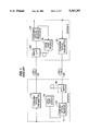
- FIG. 2 is a block diagram of an embodiment of a wavelength-stabilizing apparatus according to the present invention for use in an optical communication system.
- FIG. 3 is a block diagram of a coherent optical transmitter.
- FIG. 4 is a diagram showing the relationship between the input current and the signal light output of the coherent optical transmitter.
- FIG. 5 shows the relationship between the input current and the light output of the semiconductor laser diode LD111A when the bias input current shown in FIG. 4 and the non-return-to-zero (NRZ) signal are supplied to the LD111A simultaneously.
- NRZ non-return-to-zero
- FIG. 6 is a detailed block diagram covering the receiving section of station B shown in FIG. 2 including the coherent optical receiver 12B, the local optical source 13B, the optical mixer 15B and the optical splitter 16B.
- FIG. 7 is a detailed block diagram covering the transmitting section of station B shown in FIG. 2 and shows the coherent optical transmitter 11B, the optical splitter 19B, the optical mixer 17B and the control circuit 18B.
- FIG. 2 shows the block diagram of the invention.
- the signal light of extremely stable wavelength is generated by the coherent optical transmitter 11A at station A and sent out to the optical transmission line 100.
- the signal light received from station B is mixed with the light generated by the local light source 13A by the optical mixer 15A.
- the mixed optical signal is then converted into an electrical signal by the coherent optical receiver 12A.
- the converted electrical signal is constantly monitored by means of monitoring equipment and, depending upon the signal conditions, the local light source 13A is subject to control.
- the construction of the local light source is such that the wavelength of the light transmitted is adjusted to correspond to the wavelength of the signal light sent from station B.
- the wavelength of the signal light transmitted from the coherent optical transmitter 11A at station A, the wavelengths of the signal light transmitted from the coherent optical transmitter 11B at station B and of the generated light from the local light sources at both stations A and B are stabilized.
- FIG. 3 shows the circuit diagram of the coherent optical transmitter 11A.
- the waveform-shaping circuit 110A receives a NRZ (Non Return to Zero) signal of 1.5 Mb/s as its input, shapes it into a perfect rectangular waveform, and then supplies it to the semiconductor laser LD111A.
- NRZ Non Return to Zero
- the input-current versus light-output characteristic of the LD111A is shown in FIG. 4.
- the NRZ signal and the bias current I B shown in FIG. 4 are supplied to the LD111A simultaneously, signal light of having two different wavelength values of ⁇ 1 and ⁇ 2 ( ⁇ 1 ⁇ 2 ) are generated as shown in FIG. 5.
- the mid wavelength value between ⁇ 1 and ⁇ 2 is 1/2 ⁇ 10 14 Hz.
- the frequency difference between the signal light values corresponding to the NRZ-signal values of "1" and "0" is 4 GHz. Incidentally, the frequency difference depends upon the amplitude of the NRZ signal.
- the LD111A When a high frequency signal is input into the LD111A with a bias current which is much higher than the threshold value, the LD111A generates a signal light corresponding to the "0" and "1" of the NRZ signal. FSK modulation is carried out by this procedure.
- the output light of the LD111A is a stable light source.
- FIG. 6 shows a block diagram of the coherent optical receiver 12B, local light source 13B, optical mixer 15B and optical splitter 16B.
- the optical signal that has undergone FSK modulation coming in from the optical transmission line 100 is applied to the polarizing prism 151B.
- the polarization-diversity coherent optical receiver is shown in FIG. 6.
- This incoming optical signal is then split into two polarized light components of mutually perpendicular polarities known as "P" and "S" polarized light.
- the "P” component is incident to optical mixer 121P and the "S” component is incident to another optical mixer 121S through either one of the optical fibers, both of which are designed to preserve the polarization plane, whether it be "P" or "S”.
- the polarizing prism 152B When the light output from the local light source 13B, a semiconductor laser, is incident upon the polarizing prism 152B through the optical splitter 16B, it is split into P and S components.
- the P or S component is incident upon the optical mixer 121P or 121S, respectively, through either one of the optical fibers, both of which are capable of preserving the corresponding plane of polarization.
- the output light frequency of the local light source 13B is predetermined to be a suitable value to obtain an IF signal.
- the local light source 13B generates a local light having wavelength ⁇ 0 which maintains the frequency difference between the mean value of light frequencies corresponding to received signal "1" and "0" and ⁇ 0 at 5 GHz (the same as IF) in order to make the IF signal 5 GHz.
- optical beat signals whose frequencies are equal to the frequency difference of the two light signals are generated, and they are incident upon a pair of photo-diodes, 122P and 122S, respectively.
- Each photo-diode serves to convert the incident signal light into an electrical signal.
- the photo-diodes essentially serve as square law detectors, two components of the signal light appear in the output of each photo-diode, these components differing in frequency and phase according to the difference between the incident light transmitted to the light mixers 121P and 121S and the light generated from the local light source.
- the gains of the pair of variable gain amplifiers, 123P and 123S are always controlled to keep the output of each constant by means of a pair of control circuits 124P and 124S.
- the variable-gain amplifiers serve as the intermediate-frequency amplifiers and have an intermediate frequency and bandwidth of 5 GHz and 4 GHz, respectively. Since the outputs of the variable gain amplifiers 123P and 123S have phase differences corresponding to "1" or "0" of the signal light, respectively, the baseband signals "0" and "1" of the signal light are generated by means of the demodulation circuit, 125P and 125S, employing the technique of delayed detection. The outputs of 125P and 125S are added together by means of the signal adder 126.
- another adder 127 and automatic-frequency controller (AFC) are provided as a compensation circuit for possible variation of the output wavelength of the local light source.
- the beat frequency of the output of the light mixers, 121P and 121S may fluctuate as the result of possible wavelength fluctuations of the output of the semiconductor laser, LD13B
- the output-frequency of the variable intermediate-frequency amplifiers, 123P and 123S may deviate from 5 GHz.
- the amplitude of the 5 GHz component of the output of the variable gain amplifiers 123P and 123S may fluctuate.
- the adder 127 detects and adds the 5 GHz from the output components of the variable gain amplifiers 123P and 123S and supplies the result to the automatic-frequency controller 128. It controls the laser diode 13B so that the laser output coincides with the nominal output level of adder 127.
- the nominal output level of the adder 127 is so designed as to coincide with its output level for the case in which the difference between the intermediate-frequencies, i.e., the output, of the variable gain amplifiers 123P and 123S is precisely 5 GHz.
- This can be realized by controlling the electric current through the Peltier element to cool the laser LD13B.
- the output wavelength of a semiconductor laser is subject to temperature variations. This property can also be utilized to stabilize the output wavelength of a semiconductor laser. Generation and absorption of heat of the automatic frequency controller 128 are therefore controlled by controlling the electric current through the Peltier element.
- FIG. 7 is a block diagram of the transmitting section of station B, which consists of a coherent optical transmitter 11B, an optical splitter 19B, an optical mixer 17B and a control circuit 18B.
- the coherent optical transmitter 11B is identical with the coherent optical transmitter 11A already explained in FIG. 3.
- a beat signal having a frequency equal to the frequency difference between the optical frequencies of the output signal light from the coherent optical transmitter 11B that has been modified by the FSK technique and the local light from the local light source 13B generated by the mixer 17B can be converted into an electrical signal by means of the photo diode 181B.
- This signal that is amplified by the intermediate amplifier 182B which has an intermediate frequency of 5 GHz.
- the wavelength of the output signal light of the automatic-frequency controller 183B is stabilized by temperature control of the semiconductor laser.
- the intermediate-frequency fluctuates and, as an unavoidable result, the output level of the automatic-frequency controller (AFC) 128B which operates close to the intermediate frequency of 5 GHz also fluctuates.
- the electric current through the Peltier element used to cool the laser in the coherent optical transmitter 11B is adjusted in accordance with changes in the level of the AFC 128B.
- the polarization diversity technique is employed in the coherent optical receiver of the embodiment.
- any other system of heterodyne detection including PSK or DPSK, could be used to good effect.
- Digital modulation could also be successfully employed.
Landscapes
- Physics & Mathematics (AREA)
- Condensed Matter Physics & Semiconductors (AREA)
- General Physics & Mathematics (AREA)
- Electromagnetism (AREA)
- Optics & Photonics (AREA)
- Optical Communication System (AREA)
Priority Applications (1)
| Application Number | Priority Date | Filing Date | Title |
|---|---|---|---|
| US08/173,276 US5367397A (en) | 1990-10-15 | 1993-12-27 | Wavelength-stabilizing method and its associated circuitry for an optical communication system |
Applications Claiming Priority (4)
| Application Number | Priority Date | Filing Date | Title |
|---|---|---|---|
| JP2273314A JPH04150628A (ja) | 1990-10-15 | 1990-10-15 | 光通信システムの波長安定化方法および回路 |
| JP2-273314 | 1990-10-15 | ||
| US77541591A | 1991-10-15 | 1991-10-15 | |
| US08/173,276 US5367397A (en) | 1990-10-15 | 1993-12-27 | Wavelength-stabilizing method and its associated circuitry for an optical communication system |
Related Parent Applications (1)
| Application Number | Title | Priority Date | Filing Date |
|---|---|---|---|
| US77541591A Continuation | 1990-10-15 | 1991-10-15 |
Publications (1)
| Publication Number | Publication Date |
|---|---|
| US5367397A true US5367397A (en) | 1994-11-22 |
Family
ID=17526152
Family Applications (1)
| Application Number | Title | Priority Date | Filing Date |
|---|---|---|---|
| US08/173,276 Expired - Fee Related US5367397A (en) | 1990-10-15 | 1993-12-27 | Wavelength-stabilizing method and its associated circuitry for an optical communication system |
Country Status (2)
| Country | Link |
|---|---|
| US (1) | US5367397A (ja) |
| JP (1) | JPH04150628A (ja) |
Cited By (16)
| Publication number | Priority date | Publication date | Assignee | Title |
|---|---|---|---|---|
| US5541759A (en) * | 1995-05-09 | 1996-07-30 | Microsym Computers, Inc. | Single fiber transceiver and network |
| US5790286A (en) * | 1995-10-28 | 1998-08-04 | Samsung Electronics Co., Ltd. | Technique for embodying duplication of optical paths in optical data transmission |
| EP0889312A3 (en) * | 1997-06-30 | 1999-08-04 | Ando Electric Co., Ltd. | Apparatus for measuring characteristics of optical fiber |
| US6212311B1 (en) * | 1997-10-06 | 2001-04-03 | Fujitsu Limited | Light signal transmission system and light signal transmission method |
| US6407846B1 (en) | 2001-03-16 | 2002-06-18 | All Optical Networks, Inc. | Photonic wavelength shifting method |
| US20020131125A1 (en) * | 2001-03-16 | 2002-09-19 | Myers Michael H. | Replicated-spectrum photonic transceiving |
| US20030043426A1 (en) * | 2001-08-30 | 2003-03-06 | Baker R. J. | Optical interconnect in high-speed memory systems |
| US20030053178A1 (en) * | 2001-08-28 | 2003-03-20 | Karlquist Richard K. | Frequency translating devices and frequency translating measurement systems that utilize light-activated resistors |
| US20040208646A1 (en) * | 2002-01-18 | 2004-10-21 | Seemant Choudhary | System and method for multi-level phase modulated communication |
| DE10308306A1 (de) * | 2003-02-26 | 2004-10-28 | Siemens Ag | Verfahren und Anordnung zur Übertragung von Working-Signalen und Protection-Signalen über optische Datennetze |
| US20050100344A1 (en) * | 2003-11-06 | 2005-05-12 | Hogan Josh N. | System for coherent optical communication |
| US20070154221A1 (en) * | 2003-06-10 | 2007-07-05 | Nortel Networks Limited | Frequency agile transmitter and receiver architecture for dwdm systems |
| US20080038001A1 (en) * | 2006-03-10 | 2008-02-14 | Becker Donald A | Feedback-controlled coherent optical receiver with electrical compensation/equalization |
| US20120294614A1 (en) * | 2011-05-17 | 2012-11-22 | Nec Laboratories America, Inc. | Symmetric Coherent OFDMA-PON Configuration with Low-Speed ONU-Side |
| US20160301475A1 (en) * | 2015-04-09 | 2016-10-13 | Futurewei Technologies, Inc. | Optical Transceiving Using Self-Homodyne Detection (SHD) and Remote Modulation |
| US11398868B1 (en) * | 2021-05-31 | 2022-07-26 | Solanium Labs Ltd. | Intra data center optical communication |
Citations (7)
| Publication number | Priority date | Publication date | Assignee | Title |
|---|---|---|---|---|
| US4817206A (en) * | 1986-04-10 | 1989-03-28 | Cselt- Centro Studi E Laboratori Telecomunicazioni S.P.A. | Optical-fiber transmission system with polarization modulation and heterodyne coherent detection |
| US4888817A (en) * | 1987-10-28 | 1989-12-19 | Kokusai Denshin Denwa Kabushiki Kaisha | Polarization diversity light receiving system using baseband combining |
| JPH0239741A (ja) * | 1988-07-29 | 1990-02-08 | Nec Corp | 偏波ダイバーシチ型光ヘテロダイン受信装置 |
| US4912526A (en) * | 1985-12-20 | 1990-03-27 | Yokogawa Electric Corporation | Optical frequency synthesizer/sweeper |
| US4965858A (en) * | 1988-02-19 | 1990-10-23 | Fujitsu Limited | Polarization diversity optical receiver for coherent optical communication |
| US5052051A (en) * | 1988-10-20 | 1991-09-24 | Fujitsu Limited | Heterodyne receiver for coherent optical communication |
| US5142402A (en) * | 1988-12-16 | 1992-08-25 | Hitachi, Ltd. | Polarization diversity optical receiving apparatus and method |
-
1990
- 1990-10-15 JP JP2273314A patent/JPH04150628A/ja active Pending
-
1993
- 1993-12-27 US US08/173,276 patent/US5367397A/en not_active Expired - Fee Related
Patent Citations (7)
| Publication number | Priority date | Publication date | Assignee | Title |
|---|---|---|---|---|
| US4912526A (en) * | 1985-12-20 | 1990-03-27 | Yokogawa Electric Corporation | Optical frequency synthesizer/sweeper |
| US4817206A (en) * | 1986-04-10 | 1989-03-28 | Cselt- Centro Studi E Laboratori Telecomunicazioni S.P.A. | Optical-fiber transmission system with polarization modulation and heterodyne coherent detection |
| US4888817A (en) * | 1987-10-28 | 1989-12-19 | Kokusai Denshin Denwa Kabushiki Kaisha | Polarization diversity light receiving system using baseband combining |
| US4965858A (en) * | 1988-02-19 | 1990-10-23 | Fujitsu Limited | Polarization diversity optical receiver for coherent optical communication |
| JPH0239741A (ja) * | 1988-07-29 | 1990-02-08 | Nec Corp | 偏波ダイバーシチ型光ヘテロダイン受信装置 |
| US5052051A (en) * | 1988-10-20 | 1991-09-24 | Fujitsu Limited | Heterodyne receiver for coherent optical communication |
| US5142402A (en) * | 1988-12-16 | 1992-08-25 | Hitachi, Ltd. | Polarization diversity optical receiving apparatus and method |
Non-Patent Citations (3)
| Title |
|---|
| Glance Polarization Independent Coherent Optical Receiver Journal of Lightwave Tech. vol. LT5, No. 2, Feb. 1987. * |
| Shibutani et al, "A Study on an Active Square-Law Combining Method for a Polarization etc." IEEE Photonics Tech. Letters, vol. 1, No. 7, Jul. 1989. |
| Shibutani et al, A Study on an Active Square Law Combining Method for a Polarization etc. IEEE Photonics Tech. Letters, vol. 1, No. 7, Jul. 1989. * |
Cited By (28)
| Publication number | Priority date | Publication date | Assignee | Title |
|---|---|---|---|---|
| US5541759A (en) * | 1995-05-09 | 1996-07-30 | Microsym Computers, Inc. | Single fiber transceiver and network |
| US5790286A (en) * | 1995-10-28 | 1998-08-04 | Samsung Electronics Co., Ltd. | Technique for embodying duplication of optical paths in optical data transmission |
| EP0889312A3 (en) * | 1997-06-30 | 1999-08-04 | Ando Electric Co., Ltd. | Apparatus for measuring characteristics of optical fiber |
| US6055044A (en) * | 1997-06-30 | 2000-04-25 | Ando Electric Co., Ltd. | Apparatus for measuring characteristics of optical fiber |
| US6212311B1 (en) * | 1997-10-06 | 2001-04-03 | Fujitsu Limited | Light signal transmission system and light signal transmission method |
| US6407846B1 (en) | 2001-03-16 | 2002-06-18 | All Optical Networks, Inc. | Photonic wavelength shifting method |
| US20020131125A1 (en) * | 2001-03-16 | 2002-09-19 | Myers Michael H. | Replicated-spectrum photonic transceiving |
| US20030053178A1 (en) * | 2001-08-28 | 2003-03-20 | Karlquist Richard K. | Frequency translating devices and frequency translating measurement systems that utilize light-activated resistors |
| US9697883B2 (en) | 2001-08-30 | 2017-07-04 | Micron Technology, Inc. | Optical interconnect in high-speed memory systems |
| US20030043426A1 (en) * | 2001-08-30 | 2003-03-06 | Baker R. J. | Optical interconnect in high-speed memory systems |
| US8712249B2 (en) | 2001-08-30 | 2014-04-29 | Micron Technology, Inc. | Optical interconnect in high-speed memory systems |
| US7941056B2 (en) * | 2001-08-30 | 2011-05-10 | Micron Technology, Inc. | Optical interconnect in high-speed memory systems |
| US20110231618A1 (en) * | 2001-08-30 | 2011-09-22 | Baker Russel J | Optical interconnect in high-speed memory systems |
| US9299423B2 (en) | 2001-08-30 | 2016-03-29 | Micron Technology, Inc. | Optical interconnect in high-speed memory systems |
| US20040208646A1 (en) * | 2002-01-18 | 2004-10-21 | Seemant Choudhary | System and method for multi-level phase modulated communication |
| DE10308306A1 (de) * | 2003-02-26 | 2004-10-28 | Siemens Ag | Verfahren und Anordnung zur Übertragung von Working-Signalen und Protection-Signalen über optische Datennetze |
| DE10308306B4 (de) * | 2003-02-26 | 2006-04-20 | Siemens Ag | Verfahren und Anordnung zur Übertragung von Working-Signalen und Protection-Signalen über optische Datennetze |
| US20070154221A1 (en) * | 2003-06-10 | 2007-07-05 | Nortel Networks Limited | Frequency agile transmitter and receiver architecture for dwdm systems |
| US7526211B2 (en) * | 2003-06-10 | 2009-04-28 | Nortel Networks Limited | Frequency agile transmitter and receiver architecture for DWDM systems |
| US20050100344A1 (en) * | 2003-11-06 | 2005-05-12 | Hogan Josh N. | System for coherent optical communication |
| US20080038001A1 (en) * | 2006-03-10 | 2008-02-14 | Becker Donald A | Feedback-controlled coherent optical receiver with electrical compensation/equalization |
| US7406269B2 (en) * | 2006-03-10 | 2008-07-29 | Discovery Semiconductors, Inc. | Feedback-controlled coherent optical receiver with electrical compensation/equalization |
| US9160480B2 (en) * | 2011-05-17 | 2015-10-13 | Nec Laboratories America, Inc. | Symmetric coherent OFDMA-PON configuration with low-speed ONU-side |
| US20120294614A1 (en) * | 2011-05-17 | 2012-11-22 | Nec Laboratories America, Inc. | Symmetric Coherent OFDMA-PON Configuration with Low-Speed ONU-Side |
| US20160301475A1 (en) * | 2015-04-09 | 2016-10-13 | Futurewei Technologies, Inc. | Optical Transceiving Using Self-Homodyne Detection (SHD) and Remote Modulation |
| US9654219B2 (en) * | 2015-04-09 | 2017-05-16 | Futurewei Technologies, Inc. | Optical transceiving using self-homodyne detection (SHD) and remote modulation |
| US11398868B1 (en) * | 2021-05-31 | 2022-07-26 | Solanium Labs Ltd. | Intra data center optical communication |
| US12191914B2 (en) | 2021-05-31 | 2025-01-07 | Solanium Labs Ltd. | Intra data center optical communication |
Also Published As
| Publication number | Publication date |
|---|---|
| JPH04150628A (ja) | 1992-05-25 |
Similar Documents
| Publication | Publication Date | Title |
|---|---|---|
| US5367397A (en) | Wavelength-stabilizing method and its associated circuitry for an optical communication system | |
| CA1290019C (en) | Dual balanced optical signal receiver | |
| US5134509A (en) | Coherent subcarrier multiplexed optical communication system | |
| US7406269B2 (en) | Feedback-controlled coherent optical receiver with electrical compensation/equalization | |
| US7869719B2 (en) | Method and system for automatic feedback control for fine tuning a delay interferometer | |
| US4989200A (en) | Coherent subcarrier multiplexed optical communication system | |
| US5546190A (en) | Carrier and clock recovery for lightwave systems | |
| US20040208643A1 (en) | Coherent optical receivers | |
| EP0352809B1 (en) | Polarization diversity optical heterodyne receiver with phase adjustment of two i.f. signals for control of a local optical source | |
| US5422752A (en) | Optical transmission system | |
| US4972515A (en) | Polarization diversity receiver having little deteriorated sensitivity despite use of a square-law demodulator having a restricted dynamic range | |
| EP0325815B1 (en) | Method and device for compensating at the receiving side the phase noise of a transmitting laser and of a local laser in a coherent optical communication system with heterodyne detection | |
| EP0314491B1 (en) | Polarization diversity light receiving system | |
| US6819877B1 (en) | Optical links | |
| CN114690436B (zh) | 一种光偏振控制装置和偏振分集自相干系统 | |
| US5257126A (en) | Coherent optical fiber communications system using polarization modulation | |
| US5461504A (en) | Opto-electronic circuits | |
| JP2659417B2 (ja) | コヒーレント光通信方式 | |
| EP4117202A1 (en) | Coherent optical receiver | |
| JPS60172842A (ja) | 光受信回路制御装置 | |
| US5414550A (en) | Optical heterodyne detector and receiver | |
| JPS63198426A (ja) | 中間周波数安定化方法 | |
| Kuri et al. | 4-2 Optical Heterodyne Detection for 60-GHz-Band Radio-on-Fiber Systems | |
| JPH0583203A (ja) | 光送信機及び光受信機並びにこれらを備えた光通信システム | |
| JPH05224267A (ja) | 光受信器 |
Legal Events
| Date | Code | Title | Description |
|---|---|---|---|
| FEPP | Fee payment procedure |
Free format text: PAYOR NUMBER ASSIGNED (ORIGINAL EVENT CODE: ASPN); ENTITY STATUS OF PATENT OWNER: LARGE ENTITY |
|
| FEPP | Fee payment procedure |
Free format text: PAYOR NUMBER ASSIGNED (ORIGINAL EVENT CODE: ASPN); ENTITY STATUS OF PATENT OWNER: LARGE ENTITY |
|
| FPAY | Fee payment |
Year of fee payment: 4 |
|
| REMI | Maintenance fee reminder mailed | ||
| LAPS | Lapse for failure to pay maintenance fees | ||
| STCH | Information on status: patent discontinuation |
Free format text: PATENT EXPIRED DUE TO NONPAYMENT OF MAINTENANCE FEES UNDER 37 CFR 1.362 |
|
| FP | Lapsed due to failure to pay maintenance fee |
Effective date: 20021122 |