US5384655A - Stereoscopic viewing device - Google Patents
Stereoscopic viewing device Download PDFInfo
- Publication number
- US5384655A US5384655A US08/068,117 US6811793A US5384655A US 5384655 A US5384655 A US 5384655A US 6811793 A US6811793 A US 6811793A US 5384655 A US5384655 A US 5384655A
- Authority
- US
- United States
- Prior art keywords
- image
- stereoscope
- images
- housing
- card
- Prior art date
- Legal status (The legal status is an assumption and is not a legal conclusion. Google has not performed a legal analysis and makes no representation as to the accuracy of the status listed.)
- Expired - Lifetime
Links
Images


Classifications
-
- G—PHYSICS
- G02—OPTICS
- G02B—OPTICAL ELEMENTS, SYSTEMS OR APPARATUS
- G02B30/00—Optical systems or apparatus for producing three-dimensional [3D] effects, e.g. stereoscopic images
- G02B30/20—Optical systems or apparatus for producing three-dimensional [3D] effects, e.g. stereoscopic images by providing first and second parallax images to an observer's left and right eyes
- G02B30/34—Stereoscopes providing a stereoscopic pair of separated images corresponding to parallactically displaced views of the same object, e.g. three-dimensional [3D] slide viewers
- G02B30/37—Collapsible stereoscopes
-
- G—PHYSICS
- G02—OPTICS
- G02B—OPTICAL ELEMENTS, SYSTEMS OR APPARATUS
- G02B30/00—Optical systems or apparatus for producing three-dimensional [3D] effects, e.g. stereoscopic images
- G02B30/20—Optical systems or apparatus for producing three-dimensional [3D] effects, e.g. stereoscopic images by providing first and second parallax images to an observer's left and right eyes
- G02B30/34—Stereoscopes providing a stereoscopic pair of separated images corresponding to parallactically displaced views of the same object, e.g. three-dimensional [3D] slide viewers
- G02B30/35—Stereoscopes providing a stereoscopic pair of separated images corresponding to parallactically displaced views of the same object, e.g. three-dimensional [3D] slide viewers using reflective optical elements in the optical path between the images and the observer
Definitions
- the present invention relates to a device for the creation of a stereoscopic image from back to back stereoscopically complementary images and to a novel card bearing stereoscopically complementary images in an arrangement which allows said images to be arranged back to back for viewing with the device of the invention.
- the first developed initially in 1833 by Wheatstone, required two diametrically opposed stereoscopically complementary images, one placed to the left of the left eye at a 90 degree angle to the line of sight and the other placed to the right of the right eye also at a 90 degree angle to the line of sight.
- the system required two mirrors, one for each eye/image and the mirrors reflected the right image to the right eye and the left image to the left eye.
- the Wheatstone system suffers from the disadvantage that two physically separate images are required to provide the stereoscopic effect and the disadvantage that the stereoscope was required to be relatively wide to accomodate the placement of the two images which must be outside of the observer's head.
- Brewster invented a lens based stereoscope which produced a stereoscopic image from two stereoscopically complementary images placed side by side directly in front of the observer.
- the Brewster system has some limitations including the requirement of special lenses to produce a stereoscopic effect, the need to place the images at the focal point of the lenses and to place the lenses at a particular distance from the observer.
- U.S. Pat. No. 4,.561,723 discloses an electronic stereoscopic viewing device whereby two side by side electronically generated images are employed to create a stereoscopic effect with the aid of a combined lens and mirror system.
- the present invention relates to a stereoscopic viewing device for viewing a stereoscopic image created from first and second stereoscopically complementary images which are positioned substantially back-to-back relative to one another and substantially orthogonal to the line of sight of the observer.
- the stereoscope includes a first image conducting means including a left eye viewing port positioned substantially orthogonal to the first image and at least one reflecting means for reflecting the first image to the left eye viewing port for visual perception of the first image by the left eye of an observer.
- the stereoscopic viewing device also includes a second image conducting means including a right eye viewing port positioned substantially orthogonal to the second image and at least one reflecting means for reflecting the second image to the right eye viewing port for visual perception of the second image by the right eye of an observer.
- the device includes a means for optically insulating the first and second image conducting means from one another to restrict optical transfer of the first and second images between the first and second image conducting means.
- the present invention relates to a card adapted for use in the stereoscopic viewing device of the present invention, said card bearing two stereoscopically complementary images and being adapted such that said two stereoscopically complementary images can be positioned substantially back to back relative to one another.
- the stereoscopic viewing device of the present invention provides a convenient means of viewing a stereoscopic image created from a card bearing two stereoscopically complementary images arranged substantially back to back relative to one another.
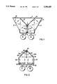
- FIG. 1 is a top view of a stereoscopic viewing device in accordance with the present invention which employs a pair of mirrors for each image conducting means.
- FIG. 2 is a top view of an alternative embodiment of a stereoscopic viewing device in accordance with the present invention which employs a combination of mirrors and lenses to form the image conducting means.
- FIG. 3 depicts the first and second sides of a stereoscopic card in accordance with the present invention.
- FIG. 4 depicts the front of a foldable stereoscopic card in accordance with the present invention.
- FIG. 5 depicts a collapsible version of a stereoscopic viewing device in accordance with the present invention.
- the device can be set up in a room, for example, and need not have a housing to be functional.
- FIG. 1 there is shown a top view of a stereoscopic device in accordance with the present invention. More particularly, the device includes a housing having a front portion 1, a left side portion 2, a right side portion 3 and a back portion 4.
- a card 5 held in place by card positioning means 6 and 7 which may be, for example, a pair of parallel, spaced runners between which the card 5 is held securely in place.
- the card 5 bears two complementary sterescopic images, the left eye image appearing on the left surface 8 of the card 5 and the right eye image appearing on the right surface 9 of the card 5.
- the image on the left surface 8 of card 5 is reflected by a first left reflective surface 10 to a second left reflective surface 11 and then to the left eye 12 of the observer via the left eye viewing port (not shown) in the front portion 1 of the housing.
- the image on the right surface 9 of card 5 is reflected by a first right reflective surface 13 to a second right reflective surface 14 and then to the right eye 15 of the observer via the right eye viewing port (not shown) in the front portion 1 of the housing.
- the viewing ports may be, in the simplest embodiment, two holes in the front portion 1 of the housing.
- the viewing ports can extend outwardly from the housing to provide room for the viewer's nose when employing the viewing device.
- the spacing between the viewing ports should be sufficient to position them at the same distance apart as the eyes of the user.
- An even more sophisticated embodiment provides horizontally adjustable viewing ports to allow adjustment of the spacing of the viewing ports to the particular eye spacing of the user.
- the stereoscope of the present invention creates a stereoscopic image from two stereoscopically complementary pictures arranged substantially back to back relative to one another.
- the device is applicable in the trading card industry, for example, where 3" ⁇ 2.5" cards can be printed bearing stereoscopically complementary images.
- the pictures on the card must be stereoscopically complementary, i.e. one picture must simulate the view of the left eye of the observer and the other picture must simulate the view of the right eye of the observer.
- substantially back to back relative to one another is meant that the images face directions which are substantially 180 degrees from one another.
- substantially is meant from 160-200 degrees from one another. To accomodate variations from 180 degrees, minor adjustments to the orientation of the reflective surfaces 10, 11, 13 and 14 can be made. Otherwise, slight variations in the angle from 180 degrees can be employed to create special visual effects, if desired.
- two back to back electronic image generating devices can be used to create a stereoscopic moving picture.
- the card 5 is replaced by, for example, two television screens placed substantially back to back relative to one another, and which display stereoscopically complementary images.
- a particularly advantageous feature of the device of the present invention is the placement of the first and second images orthogonal to the line of sight of the observer. This leads not only to the ability to employ a single card to generate the stereoscopic image, but also provides a convenient means for optically isolating the left portion of the viewing device from the right portion of the viewing device.
- the card 5 serves the dual function of providing the required stereoscopically complementary images and also optically isolates the left and right portions of the stereoscope thereby preventing contamination of the right eye image by the left eye image and vice versa.
- the device can function with any number of optical transmission means including reflective surfaces, lenses, prisms and even optical fibers.
- the image conducting means is not limited to the particular means shown in the drawings.
- the image conducting means may be affixed to the inside of the housing. In another embodiment, the image conducting means may form an integral part of said housing.
- the device of FIG. 2 comprises a housing Including a front portion 21, a left portion 22, a right portion 23 and a back portion 24a and 24b.
- a card 25 held in place by card positioning means 26 which may be, for example, a pair of parallel, spaced runners between which the card 25 is held securely in place.
- the card 25 bears two complementary sterescopic images, the left eye image appearing on the left surface 27 of the card 25 and the right eye image appearing on the right surface 28 of the card 25.
- the left eye image on the left surface 27 of the card 25 is reflected by the left reflective surface 29 to the left lens 30 which then focuses the left eye image onto the left eye 31 of the observer via the left eye viewing port (not shown) in the front portion 21 of the housing.
- the right eye image on the right surface 28 is reflected by the right reflective surface 32 to the right lens 33 which then focuses the right eye image on the right eye 34 of the observer via the right eye viewing port (not shown) in the front portion 21 of the housing.
- FIG. 2 A variation on the theme of FIG. 2 is to employ a four mirror system as shown in FIG. 1 and to include an image refracting means in the viewing ports. These image refracting-means may be used to focus the image or to enlarge or reduce it in size. Another possibility is to employ the image refracting means in the viewing ports to focus on and magnify particular portions of the image. Of course, removable viewing ports or viewing ports including several different lenses which can be independently employed, can be used to achieve different levels of magnification or any other desired effects.
- the housing In order to provide the highest quality stereoscopic image, it is preferred to build the housing from a light reflective material such as white card stock, plastic and/or other white or light colored material. Further, it is preferred to leave the top and/or the bottom of the housing open to allow light to enter the housing and illuminate the stereoscopically complementary images.
- optional caps for the top and bottom can be provided. The cap(s) could, for example, snap on and off so that during use, sufficient light would be available for viewing the stereoscopic image and, when not in use, the cap(s) can be replaced to keep the inside of the stereoscope clean.
- One or both of the cap(s) may also include a slot or a reclosable opening to allow insertion of the card S through the cap(s) into the card positioning means 6,7 without removing the cap(s) from the stereoscope.
- the top and/or bottom of the housing may be made from a light transmitting material such as clear plastic and may optionally be removable.
- the stereoscope can be closed on all sides keeping the reflective surfaces clean and making shipping and handling more convenient, while still allowing sufficient light inside to illuminate the card 5.
- an artificial light source can be included in the housing or the top or bottom cap. Even lighting of the pictures is important to provide a good quality stereoscopic image and thus, a dome-shaped cap made from a light-reflective material and including a light source, is preferred.
- the housing forms a shell into which a removable insert may be inserted.
- a removable insert is preferably made from a clear or light reflective material and may be designed to fit snugly into the housing.
- One or more of the reflective surfaces 10,11,13,14 are affixed to, or form an integral part of, the removable insert such that when the insert is placed in the housing the reflective surfaces 10,11,13,14 are properly positioned to produce the stereoscopic image.
- the remaining reflective surfaces 10,11,13,14 may be associated with the housing.
- the primary advantage of this embodiment is that it allows convenient and easy replacement of one or more reflective surfaces 10,11,13,14. In this manner, repair of the device is facilitated and, more importantly, a variety of special stereoscopic effects can be produced by inserting different types of reflective surfaces 10,11,13,14 into the stereoscope. For instance, curved reflective surfaces can be employed to make images look wider, narrower, longer, shorter, etc.
- means may be provided in the housing or the cap(s) for the storage of a plurality of cards.
- Such means may be in the form of a slot in one or more of the portions 1-4 of the housing or the cap(s), or in the form of a recess in one or more of the same locations, said recess being provided with some means for retaining the cards in place during storage.
- Other card storage means are possible and the most preferred means will be determined by the number of cards to be stored and the costs of production for the particular design including such means.
- the stereoscope of the present invention may also be offered in the form of a model kit of parts along with assembly instructions.
- This embodiment has the advantages of allowing the device to be mailed or shipped in a more convenient form and it caters to the do-it-yourself market who may wish to assemble and customize their stereoscope.
- the design would be essentially the same as that shown in FIGS. 1-2 except that at least the housing would be made up of several distinct parts which would have to be assembled.
- the card 5 comprises a front side 40 and a back side 41 which are interchangeable.
- the front side 40 bears the left eye image 42 of the stereoscopic picture to be seen by the viewer.
- the back side 41 bears the right eye image 43 of the stereoscopic picture.
- the card 5 is positioned in the stereoscopic viewer so that the left eye image 42 races the left eye side of the viewer and the right eye image 43 faces the right eye side of the viewer.
- the card 5 may also contain text 44 on one or both sides of the card 5.
- the card 5 of FIG. 3 is the most preferred embodiment of the present invention as it allows current manufacturers of 3" ⁇ 2.5" trading cards to switch over to the production or stereoscopic trading cards without having to make significant changes in their machinery and/or manufacturing processes.
- the text 44 is optional and need not be included on the card. However, if text is desirable, for example for statistics to go along with an action photograph of a sports personality, it can be included anywhere on the card so long as the portion of the card which aligns with the image conducting means of the stereoscope still contains the stereoscopically complementary images. Thus, the stereoscope could allow viewing of, for example, only 60% of the card surface to thereby leave 40% of the card surface for textual matter.
- FIG. 4 there is shown an alternative embodiment of a card 5 in accordance with the present invention. More particularly, in FIG. 4 is shown one surface of a foldable card 45 having a top portion 46 and a bottom portion 47, which are interchangeable. The top portion 46 is divided from the bottom portion 47 by a fold line 48.
- the top portion 46 bears the left eye image 49 and the bottom portion 47 bears the right eye image 50. Again, either or both of the top portion 46 and the bottom portion 47 may bear text 51. However, in this embodiment of the invention, it is preferred to put text on the opposite surface (not shown) of the card 45.
- the card 5 of FIG. 4 represents an alternative embodiment of the invention which is particularly useful in circumstances where it is desirable to include a significant amount of textual information along with the stereoscopic image on the card. This embodiment would be particularly suitable for a travel log or for educational stereoscopic cards.
- the card 5 may fold as shown in FIG. 4 or the stereoscopically complementary images can appear side by side on the same surface of the card 5.
- the card 5 with side by side images would also fold in half between the images to thereby allow the images to be arranged substantially back to back in the stereoscopic viewing device.
- additional information about the picture can be provided by adding a magnetic strip to the card 5 and equipping the stereoscopic device with a means for reading and displaying the contents of the magnetic strip.
- FIG. 5 there is shown a top view of a collapsible version of a stereoscope in accordance with the present invention, which stereoscope is partially collapsed in FIG. 5.
- the collapsible device shown in FIG. 5 includes a housing having a front portion 1, a left side portion 2, a right side portion 3, a back portion 4, and a bottom portion 18.
- card positioning means 6 and 7 which may be, for example, a pair of parallel, spaced runners between which the card is held securely in place. Also shown in FIG. 5 are the first left reflective surface 10, the second left reflective surface 11 and the left eye viewing port 16 in the front portion 1 of the housing.
- the stereoscopically complementary image on the right surface of the card is reflected by a first right reflective surface 13 to a second right reflective surface 14 and then to the right eye of the observer via the right eye viewing port 17 in the front portion 1 of the housing.
- FIG. 5 The collapsible device depicted in FIG. 5 is already partially collapsed in that the front portion 1 of the housing is shown folded 90° from its vertical position.
- back portion 4 is attached to bottom portion 18 along back edge 19 as indicated by the four arrows in FIG. 5 and back portion 4 is perpendicular to bottom portion 18.
- the front portion 1 is first folded 180° along fold line 41.
- back portion 4 is folded 90° along fold line 42.
- the device is then folded downward 180° along central fold line 43.
- the device is folded upwards 180° along diagonal fold lines 44,45.
- the device is again folded downwards 270° along fold lines 46,47 to obtain a compact, flat object.
- a protective sleeve (not shown) would be employed to protect the reflective surfaces which would be exposed on the outside surfaces of the folded-up device.
Landscapes
- Physics & Mathematics (AREA)
- General Physics & Mathematics (AREA)
- Optics & Photonics (AREA)
- Stereoscopic And Panoramic Photography (AREA)
- Transition And Organic Metals Composition Catalysts For Addition Polymerization (AREA)
- Polishing Bodies And Polishing Tools (AREA)
- Steroid Compounds (AREA)
- Eye Examination Apparatus (AREA)
- Radiation-Therapy Devices (AREA)
Priority Applications (9)
| Application Number | Priority Date | Filing Date | Title |
|---|---|---|---|
| US08/068,117 US5384655A (en) | 1992-12-09 | 1993-05-27 | Stereoscopic viewing device |
| CA002150227A CA2150227A1 (en) | 1992-12-09 | 1993-12-08 | Stereoscopic viewing device |
| JP6514377A JPH08507385A (ja) | 1992-12-09 | 1993-12-08 | 立体観察装置 |
| PCT/US1993/011940 WO1994014099A1 (en) | 1992-12-09 | 1993-12-08 | Stereoscopic viewing device |
| EP94907090A EP0680621B1 (de) | 1992-12-09 | 1993-12-08 | Stereoskopisches betrachtungsgeraet |
| AU60487/94A AU684266B2 (en) | 1992-12-09 | 1993-12-08 | Stereoscopic viewing device |
| DE69333860T DE69333860D1 (de) | 1992-12-09 | 1993-12-08 | Stereoskopisches betrachtungsgeraet |
| AT94907090T ATE303609T1 (de) | 1992-12-09 | 1993-12-08 | Stereoskopisches betrachtungsgeraet |
| US08/334,399 US5517355A (en) | 1992-12-09 | 1994-11-03 | Card adapted for use in stereoscope |
Applications Claiming Priority (2)
| Application Number | Priority Date | Filing Date | Title |
|---|---|---|---|
| US98820692A | 1992-12-09 | 1992-12-09 | |
| US08/068,117 US5384655A (en) | 1992-12-09 | 1993-05-27 | Stereoscopic viewing device |
Related Parent Applications (1)
| Application Number | Title | Priority Date | Filing Date |
|---|---|---|---|
| US98820692A Continuation-In-Part | 1992-12-09 | 1992-12-09 |
Related Child Applications (1)
| Application Number | Title | Priority Date | Filing Date |
|---|---|---|---|
| US08/334,399 Division US5517355A (en) | 1992-12-09 | 1994-11-03 | Card adapted for use in stereoscope |
Publications (1)
| Publication Number | Publication Date |
|---|---|
| US5384655A true US5384655A (en) | 1995-01-24 |
Family
ID=26748594
Family Applications (2)
| Application Number | Title | Priority Date | Filing Date |
|---|---|---|---|
| US08/068,117 Expired - Lifetime US5384655A (en) | 1992-12-09 | 1993-05-27 | Stereoscopic viewing device |
| US08/334,399 Expired - Lifetime US5517355A (en) | 1992-12-09 | 1994-11-03 | Card adapted for use in stereoscope |
Family Applications After (1)
| Application Number | Title | Priority Date | Filing Date |
|---|---|---|---|
| US08/334,399 Expired - Lifetime US5517355A (en) | 1992-12-09 | 1994-11-03 | Card adapted for use in stereoscope |
Country Status (8)
| Country | Link |
|---|---|
| US (2) | US5384655A (de) |
| EP (1) | EP0680621B1 (de) |
| JP (1) | JPH08507385A (de) |
| AT (1) | ATE303609T1 (de) |
| AU (1) | AU684266B2 (de) |
| CA (1) | CA2150227A1 (de) |
| DE (1) | DE69333860D1 (de) |
| WO (1) | WO1994014099A1 (de) |
Cited By (5)
| Publication number | Priority date | Publication date | Assignee | Title |
|---|---|---|---|---|
| DE10000189A1 (de) * | 2000-01-05 | 2001-07-12 | Deutsche Telekom Ag | Stereobildbetrachter und zugehörige Bildträger |
| US6487013B2 (en) | 1999-07-20 | 2002-11-26 | Monte Jerome Ramstad | Folding prism stereoscope |
| US20060018016A1 (en) * | 2004-07-22 | 2006-01-26 | Nikiforov Oleg K | Device for viewing stereoscopic images on a display |
| US20060098282A1 (en) * | 2002-07-02 | 2006-05-11 | Mccart John R | Visual media |
| EP1490720B1 (de) * | 2002-03-07 | 2009-02-25 | Flir Systems AB | Einrichtung zur bi-monokularen bilddarstellung |
Families Citing this family (4)
| Publication number | Priority date | Publication date | Assignee | Title |
|---|---|---|---|---|
| EP0744644A1 (de) * | 1995-05-23 | 1996-11-27 | Christian Körber | Vorrichtung zur stereoskopischen Betrachtung |
| US5694260A (en) * | 1995-12-11 | 1997-12-02 | Houston; Christopher M. | Video visual effects generator |
| US6087558A (en) | 1998-07-22 | 2000-07-11 | Prodigene, Inc. | Commercial production of proteases in plants |
| CN103345069A (zh) * | 2013-07-11 | 2013-10-09 | 高生亮 | 便携折叠式电脑立体观看器 |
Citations (2)
| Publication number | Priority date | Publication date | Assignee | Title |
|---|---|---|---|---|
| US906774A (en) * | 1907-09-07 | 1908-12-15 | Walter Ernest Colwell | Mailing and advertising card. |
| US4457584A (en) * | 1982-03-08 | 1984-07-03 | Pryor Eugene F | Stereoscopic viewer with variable fields of vision |
Family Cites Families (17)
| Publication number | Priority date | Publication date | Assignee | Title |
|---|---|---|---|---|
| US472196A (en) * | 1892-04-05 | Stereoscopic album | ||
| US40654A (en) * | 1863-11-17 | Stereoscope and photographic album | ||
| US871974A (en) * | 1905-02-06 | 1907-11-26 | William Verbeck | Folding stereoscope. |
| US1579025A (en) * | 1924-05-07 | 1926-03-30 | Freeman H Owens | Stereoscopic apparatus |
| US2511334A (en) * | 1947-04-28 | 1950-06-13 | Wilhelm B Gruber | Stereoscopic viewer |
| US2616333A (en) * | 1950-02-11 | 1952-11-04 | Theodore B Tinker | Foldable stereoscopic device |
| US2683391A (en) * | 1951-01-17 | 1954-07-13 | John M Nichols | Stereoscopic book device |
| US2842027A (en) * | 1956-05-23 | 1958-07-08 | Betti Adriano | Stereoscopic device in the form of a book |
| FR1182710A (fr) * | 1957-09-13 | 1959-06-29 | Stéréoscope pour examen des films souples ou papiers sans interversion des vues | |
| FI40752B (de) * | 1968-06-06 | 1969-01-31 | T Mannila | |
| US3850505A (en) * | 1973-03-15 | 1974-11-26 | Jetru Inc | Universal stereoscopic viewing device |
| US3888564A (en) * | 1973-10-11 | 1975-06-10 | Marvin E Lebow | Viewing system providing compatability between two dimensional pictures and three dimensional viewing thereof |
| US4150781A (en) * | 1974-08-08 | 1979-04-24 | Johnson Everett A | Access authentication system |
| JPS58166385U (ja) * | 1982-04-28 | 1983-11-05 | 株式会社トミー | 立体視ゲ−ム装置 |
| US5136423A (en) * | 1989-04-10 | 1992-08-04 | Curtin James J | Mailable 3-D viewers of post card size |
| US4998799A (en) * | 1989-12-04 | 1991-03-12 | Brown Dennis L | Stereoscope |
| JPH0566361A (ja) * | 1990-05-11 | 1993-03-19 | Junichi Tanaka | 各種映像の臨場感を増強する光学系並びにテレビジヨンを組み込んだ光学系 |
-
1993
- 1993-05-27 US US08/068,117 patent/US5384655A/en not_active Expired - Lifetime
- 1993-12-08 JP JP6514377A patent/JPH08507385A/ja active Pending
- 1993-12-08 CA CA002150227A patent/CA2150227A1/en not_active Abandoned
- 1993-12-08 WO PCT/US1993/011940 patent/WO1994014099A1/en not_active Ceased
- 1993-12-08 AT AT94907090T patent/ATE303609T1/de not_active IP Right Cessation
- 1993-12-08 EP EP94907090A patent/EP0680621B1/de not_active Expired - Lifetime
- 1993-12-08 AU AU60487/94A patent/AU684266B2/en not_active Ceased
- 1993-12-08 DE DE69333860T patent/DE69333860D1/de not_active Expired - Lifetime
-
1994
- 1994-11-03 US US08/334,399 patent/US5517355A/en not_active Expired - Lifetime
Patent Citations (2)
| Publication number | Priority date | Publication date | Assignee | Title |
|---|---|---|---|---|
| US906774A (en) * | 1907-09-07 | 1908-12-15 | Walter Ernest Colwell | Mailing and advertising card. |
| US4457584A (en) * | 1982-03-08 | 1984-07-03 | Pryor Eugene F | Stereoscopic viewer with variable fields of vision |
Cited By (5)
| Publication number | Priority date | Publication date | Assignee | Title |
|---|---|---|---|---|
| US6487013B2 (en) | 1999-07-20 | 2002-11-26 | Monte Jerome Ramstad | Folding prism stereoscope |
| DE10000189A1 (de) * | 2000-01-05 | 2001-07-12 | Deutsche Telekom Ag | Stereobildbetrachter und zugehörige Bildträger |
| EP1490720B1 (de) * | 2002-03-07 | 2009-02-25 | Flir Systems AB | Einrichtung zur bi-monokularen bilddarstellung |
| US20060098282A1 (en) * | 2002-07-02 | 2006-05-11 | Mccart John R | Visual media |
| US20060018016A1 (en) * | 2004-07-22 | 2006-01-26 | Nikiforov Oleg K | Device for viewing stereoscopic images on a display |
Also Published As
| Publication number | Publication date |
|---|---|
| EP0680621B1 (de) | 2005-08-31 |
| JPH08507385A (ja) | 1996-08-06 |
| EP0680621A4 (de) | 1996-08-14 |
| AU6048794A (en) | 1994-07-04 |
| CA2150227A1 (en) | 1994-06-23 |
| ATE303609T1 (de) | 2005-09-15 |
| US5517355A (en) | 1996-05-14 |
| WO1994014099A1 (en) | 1994-06-23 |
| DE69333860D1 (de) | 2005-10-06 |
| EP0680621A1 (de) | 1995-11-08 |
| AU684266B2 (en) | 1997-12-11 |
Similar Documents
| Publication | Publication Date | Title |
|---|---|---|
| JP4263461B2 (ja) | 自動立体光学装置 | |
| US6070349A (en) | Multi-purpose easel for displaying multiple, 3D, and animated images | |
| US5384655A (en) | Stereoscopic viewing device | |
| US5119234A (en) | Camera for stereoscopic images | |
| US7113334B2 (en) | Autostereoscopic vision system | |
| JP2004533650A5 (de) | ||
| US4464015A (en) | Binocular stereoscopic viewers | |
| US4998799A (en) | Stereoscope | |
| US5136423A (en) | Mailable 3-D viewers of post card size | |
| US3888564A (en) | Viewing system providing compatability between two dimensional pictures and three dimensional viewing thereof | |
| JPH0373913A (ja) | 光学収束の新原理に基づく万能立体ビュアー | |
| US6046850A (en) | Stereoscope apparatus | |
| US20050243418A1 (en) | Adjustable display stereoscope | |
| JPH06133340A (ja) | 立体画像再生装置 | |
| WO1991018314A1 (fr) | Systeme optique servant a intensifier l'impression de presence dans des sites d'images diverses | |
| US20260042032A1 (en) | 3d collection card system | |
| WO1998010322A1 (en) | Head worn stereoscopic display device, particularly for displaying television pictures | |
| GB2208013A (en) | Stereo viewer | |
| JPH07140419A (ja) | 立体視方法とそれに用いる立体視眼鏡及びその製法 | |
| KR0148435B1 (ko) | 입체화상 구현 시스템 및 그 제작방법 | |
| KR200344413Y1 (ko) | 입체카드 투시기 | |
| GB2390909A (en) | Display device having diverging display surfaces | |
| JPH095669A (ja) | 立体視ビュアー | |
| CN2169146Y (zh) | 一种简易立视镜 | |
| JPH078823U (ja) | ステレオビュア |
Legal Events
| Date | Code | Title | Description |
|---|---|---|---|
| STPP | Information on status: patent application and granting procedure in general |
Free format text: APPLICATION UNDERGOING PREEXAM PROCESSING |
|
| FEPP | Fee payment procedure |
Free format text: PAYOR NUMBER ASSIGNED (ORIGINAL EVENT CODE: ASPN); ENTITY STATUS OF PATENT OWNER: SMALL ENTITY |
|
| FPAY | Fee payment |
Year of fee payment: 4 |
|
| FPAY | Fee payment |
Year of fee payment: 8 |
|
| REMI | Maintenance fee reminder mailed | ||
| FPAY | Fee payment |
Year of fee payment: 12 |
|
| SULP | Surcharge for late payment |
Year of fee payment: 11 |