US5425086A - Load control system for controlling a plurality of processes and exchange system having load control system - Google Patents
Load control system for controlling a plurality of processes and exchange system having load control system Download PDFInfo
- Publication number
- US5425086A US5425086A US07/945,957 US94595792A US5425086A US 5425086 A US5425086 A US 5425086A US 94595792 A US94595792 A US 94595792A US 5425086 A US5425086 A US 5425086A
- Authority
- US
- United States
- Prior art keywords
- call
- processes
- types
- load
- load processing
- Prior art date
- Legal status (The legal status is an assumption and is not a legal conclusion. Google has not performed a legal analysis and makes no representation as to the accuracy of the status listed.)
- Expired - Lifetime
Links
Images


Classifications
-
- H—ELECTRICITY
- H04—ELECTRIC COMMUNICATION TECHNIQUE
- H04Q—SELECTING
- H04Q3/00—Selecting arrangements
- H04Q3/42—Circuit arrangements for indirect selecting controlled by common circuits, e.g. register controller, marker
- H04Q3/54—Circuit arrangements for indirect selecting controlled by common circuits, e.g. register controller, marker in which the logic circuitry controlling the exchange is centralised
- H04Q3/545—Circuit arrangements for indirect selecting controlled by common circuits, e.g. register controller, marker in which the logic circuitry controlling the exchange is centralised using a stored program
- H04Q3/54575—Software application
- H04Q3/54591—Supervision, e.g. fault localisation, traffic measurements, avoiding errors, failure recovery, monitoring, statistical analysis
-
- H—ELECTRICITY
- H04—ELECTRIC COMMUNICATION TECHNIQUE
- H04M—TELEPHONIC COMMUNICATION
- H04M3/00—Automatic or semi-automatic exchanges
- H04M3/22—Arrangements for supervision, monitoring or testing
- H04M3/36—Statistical metering, e.g. recording occasions when traffic exceeds capacity of trunks
- H04M3/365—Load metering of control unit
Definitions
- the present invention generally relates to a load control system for controlling a plurality of processes, and more particularly a load control system included in a switching system, such as an exchange system having a plurality of processes for incoming calls.
- FIG. 1 is a graph showing how incoming calls are regulated by a conventional load control system of an exchange system shown in FIG. 2A.
- the horizontal axis of the graph of FIG. 1 represents the number of incoming calls, and the vertical axis thereof represents the rate of accepted calls to the incoming calls.
- FIG. 2B is a flowchart showing the operation of the conventional load control system shown in FIG. 2A.
- the conventional load control system has two types of processes for incoming calls, one of which is a call acceptance process, and the other one of which is a call regulation process.
- a call processing unit 2 of a processing unit 1 shown in FIG. 2A receives an incoming call received from a calling station or a called station in step S1 shown in FIG. 2B.
- the call processing unit 2 increments the value of a counter for counting the number of incoming calls by 1.
- the call processing unit 2 receives data indicative of a call regulation rate from a regulation processing unit 3 of the processing unit 1, and determines, in step S3, whether or not the received call should be accepted by referring to the call regulation rate data.
- a load state monitoring unit 4 of the exchange system periodically monitors the state of a system load which shows, for example, how frequently the processing unit 1 of the exchange system is used for processing incoming calls.
- the load state monitoring unit 4 is externally provided with a parameter A representing an upper load limit, while the unit 4 periodically reads data indicating the system load state in step S7.
- the load state monitoring unit 4 compares the upper load limit with the data indicating the system load state, and determines whether or not the processing unit 1 has an overload. When it is determined that the processing unit 1 is operating with a normal, the process ends.
- the load state monitoring unit 4 updates, in step S9, the call regulation rate to be used in the next cycle.
- the updated call regulation rate is used when the next incoming call is processed.
- the call regulation process is started when the number of incoming calls has reached a point "a", and all incoming calls are regulated (not accepted) when the number of incoming calls has reached a point "b".
- the number of accepted calls is gradually decreased as the number of incoming calls increases between the points "a" and "b" When the number of incoming calls exceeds the point "b", the call acceptance process is not carried out at all. This substantially degrades the communications services.
- a more specific object of the present invention is to provide a load control system for an exchange system capable of efficiently accepting incoming calls within a suitable load range without excessively performing processes other than the call acceptance process.
- a load control system having n types of processes provided for processing requests of an identical type, the load control system comprising: load processing means for executing one of m types of processes among the n types of processes in response to one of the processing requests where n and m are respectively integers equal to or larger than 1 and m is equal to or smaller than n; monitor means, coupled to the load processing means, for periodically monitoring a load of the load processing means and for selecting the m types of processes from among the n types of processes on the basis of the load of the load processing means; and execution ratio calculation means, coupled to the load processing means and the monitor means, for determining execution ratios of the m types of processes so that the load of the load processing means is equal to or lower than a first reference value and an execution ratio of at least one of the types of processes is equal to or higher than a second reference value, the load processing means executing the m types of processes in response to the processing requests with the execution ratios of the m types of processes.
- Another object of the present invention is to provide an exchange system using the above load processing system.
- an exchange system having n types of processes provided for call processing requests
- the load control system comprising: load processing means for executing one of m types of call processes among the n types of call processes in response to one of the call processing requests where n and m are respectively integers equal to or larger than 1 and m is equal to or smaller than n; monitor means, coupled to the lead processing means, for periodically monitoring a load of the load processing means and for selecting the m types of call processes from among the n types of processes on the basis of the lead of the lead processing means; and execution ratio calculation means, coupled to the lead processing means and the monitor means, for determining execution ratios of the m types of call processes so that the lead of the lead processing means is equal to or lower than a first reference value and an execution ratio of at least one of the types of call processes is equal to or higher than a second reference value, the lead processing means executing the m types of call processes in response to the processing requests with the execution ratios of the m types of call processes.
- FIG. 1 is a graph showing how incoming calls are processed by means of a conventional load control system
- FIG. 2A is a block diagram of a convention load control system of an exchange system
- FIG. 2B is a flowchart of a conventional lead control process
- FIG. 3A is a block diagram showing an overview of a load control system according to an embodiment of the present invention.
- FIG. 3B is a diagram showing a relationship among a plurality of processes handled by the load control system shown in FIG. 3A;
- FIG. 4 is a diagram illustrating how the processes are controlled by the load control system
- FIG. 5 is a block diagram showing an overview of an exchange system to which the present invention is applied.
- FIG. 6 is a diagram illustrating how incoming calls are processed in the exchange system shown in FIG. 5;
- FIG. 7 is a flowchart of a process for determining ratios of execution of processes
- FIG. 8 is a diagram showing a process for calculating average processor operation times
- FIG. 9 is a block diagram of a hardware structure for executing the process shown in FIG. 8;
- FIG. 10 is a flowchart of a process for calculating the average processor operation times
- FIG. 11 is a flowchart showing the operation of a CPU shown in FIG. 9 and the operation of a controller shown in FIG. 9;
- FIG. 12 is a diagram showing how incoming calls are processed by the procedure shown in FIG. 11;
- FIG. 13 is a flowchart showing a process for calculating average processor operation times in a case where four different types of processes are employed.
- FIG. 14 is a block diagram of a communications network to which the present invention is applied.
- FIG. 3A is a block diagram showing an overview of a load control system according to an embodiment of the present invention.
- FIG. 3B is a diagram showing the relationship among a plurality of types of processes executed in the exchange system shown in FIG. 3A.
- the load control system shown in FIG. 3A comprises a load processing unit 11, and a load monitoring control unit 14.
- the load control unit 11 comprises a controller 12, which selectively executes a plurality of processes (types) A, B, C, ....
- the load monitoring control unit 14 comprises a load state monitor 15, and an execution ratio computer 16.
- the load state monitor 15 periodically monitors a total load of the load processing unit 11 (such a total load is also referred to as a system load).
- the load of the load processing unit 11 corresponds to, for example, the time necessary to complete a process.
- the execution ratio computer 16 is notified of the system load monitored by the load state monitor 15, while it is externally notified of a reference value (maximum allowable load quantity) X of the system load.
- the execution ratio is defined as a ratio(s) of a specific one or a plurality of types of processes to a predetermined system load.
- the execution ratio computer 16 is externally informed of a reference value Y of the execution ratio.
- the execution ratio computer 16 computes the execution ratio on the basis of the following criteria.
- the system load must be equal to or smaller than the reference value X.
- the controller 12 is informed of the execution ratio thus computed by the execution ratio computer 16, and selectively handles requests for execution of processes so that the above-mentioned three criteria are satisfied.
- FIG. 3B shows a priority order which defines the relationship among the priority levels of the processes (types) A, B, C, ..., n, in which the process type A has the highest priority over the other processes, the process B has the second highest priority, and the process n has the lowest priority.
- the execution ratio computer 16 selects one or a plurality of process types and calculates the execution ratio.
- the controller 12 of the load processing unit 11 executes the processes in accordance with the execution ratio calculated by the execution ratio computer 16.
- FIG. 4 is a graph of the execution ratios of the processes A-D.
- the horizontal axis of the graph shown in FIG. 4 denotes the number of processes requested, and the vertical axis thereof denotes the system load.
- the reference Y of the execution ratio of the specific process A is defined. While a relatively small number of requested processes is received, only the process A having the highest priority level is executed. When the number of requested processes has reached a point [1], it is determined that the system load has become equal to the reference value X. Hence, the process B having the second priority level is executed while the process A continues to be executed.
- the execution ratios of the processes A and B are determined on the basis of the number of requested processes.
- the process C is allowed to be executed in parallel with the processes A and B so that the system load is equal to the reference value X and the execution ratio of the process A is equal to or higher than the reference ratio Y.
- the execution ratio of the process B and the execution ratio of the process C are determined on the basis of the number of requested processes.
- the process B is not allowed to be executed, and the process D having the fourth priority level is allowed be executed in lieu of the process B.
- the processes A, C and D are executed in parallel thereto.
- FIG. 5 is a block diagram of an exchange system to which the present invention is applied.
- the exchange system shown-in FIG. 5 comprises a network (NW) 30, a central processing unit (CC; hereinafter simply referred to as a processor) 31, a main memory (MM) 32, and a monitor unit 33.
- NW network
- CC central processing unit
- MM main memory
- monitor unit 33 A plurality of subscriber lines or transmission lines connected to other exchange systems are connected to the network 30.
- the processor 31 controls transmission and reception of call control information or other information with respect to the subscriber lines and the transmission lines, and controls switching of the network 30.
- the load state of the exchange system that is, the load of the processor 31 is monitored by the monitor unit 33, which has the functions of both the load state monitor 15 and the execution ratio computer 16.
- the monitor unit 33 periodically gathers information concerning the state of the processor 31, the number of calls requested for processing applied to the processor 31, the number of calls which has been completed, and the number of calls for each of the processes, and determines which process types should be selected or executed. Then, the monitor unit 33 periodically generates a control output signal indicating the execution ratios of the process types selected.
- the present embodiment of the present invention has three different types of processes.
- the first process type is a call acceptance process
- the other two process types are call regulation processes, one of which processes is a call rejecting process, and the other one of which processes is a call discarding process.
- the call rejecting process notifies a station which generates a request for processing a call that the call acceptance process has been regulated. For example, a busy tone signal or a message is sent to the station which generates a request for call processing.
- the call discarding process discards a request for processing a call without notification of the regulation of the call acceptance process.
- the load state of the exchange system corresponds to the time it takes the processor 31 to process the requests.
- the monitor unit 33 gathers the aforementioned information at intervals of, for example, four seconds.
- the monitor unit 33 has first information indicating the upper limit X of the load of the processor 31, and second information indicating the lower limit Y of the rate of accepted calls to all the calls. That is, the first information is related to the rate of operation of the processor 31, and the second information is related to the ratio of acceptance of calls.
- the monitor unit 33 executes the regulation control so that the rate of operation of the unit 33 is prevented from exceeding the upper limit X, and concurrently the rate of acceptance of call is prevented from becoming lower than the lower limit Y.
- the following decision is made based on various pieces of data including the rate of operation of the processor 31 obtained from the data gathered by the monitor unit 33.
- the ratio of the number of calls accepted, the number of calls rejected and the number of calls discarded is adjusted.
- the suitable case is such that the rate of operation of the processor 31 is lower than the upper limit under the condition that the number of calls rejected is zero and the number of calls discarded is also zero. If the rate of operation of the processor 31 is equal to or higher than the upper limit X under the above-mentioned condition, the ratios of the process types are adjusted in the following three manners so that the rate of operation of the processor 31 is equal to the upper limit X.
- the ratios of the respective process types regulated according to the above-mentioned theory are shown in FIG. 6.
- the rate of operation of the processor 31 has reached the upper limit X, and hence the call rejecting process is started in addition to the call accepting process.
- the rate of calls accepted has reached the lower limit, and hence the call discarding process is started in addition to the call accepting process and the call rejecting process.
- the call rejecting process is stopped, and only the call discarding process is carried out as the regulation process.
- FIG. 7 is a flowchart showing the operation of the monitor unit 33.
- Various parameters used for the operation of the monitor unit 33 are stored in the main memory 32.
- the following parameters, which are measured by the monitor unit 33, indicate the load state of the processor 31:
- N The number of all incoming calls
- Oa target number of calls accepted, which is equal to Oc ⁇ N/100.
- the allowable number of calls accepted, the allowable number of calls rejected and the allowable number of calls discarded, which allowable numbers are used during the next cycle, are computed under the following conditions so that T ⁇ Ot, when R>0, D>0 or T>Ot.
- the number of incoming calls which will be generated during the next cycle is estimated as the number of incoming calls which are generated during the current cycle.
- One or more process types to be executed during the next cycle and the ratio of execution thereof can be obtained during the current cycle by using the above parameters, the expressions and the conditions (1)-(4), as shown in FIG. 7.
- the monitor unit 33 determines whether or not A ⁇ Oa in step S12.
- An ⁇ Oa that is, the number of calls accepted exceeds the target number of calls accepted
- step S13 the monitor unit 33 sets the allowable number of calls accepted during the next cycle to be equal to An, and gives no limitation to the allowable number of calls rejected.
- step S15 the monitor unit 33 determines whether or not Rn ⁇ 0.
- step S16 the monitor unit 33 sets the allowable number of calls accepted and the allowable number of calls rejected during the next cycle to be equal to An and Rn, respectively.
- step S18 the monitor unit 33 determines whether or not An ⁇ 0.
- the monitor unit 33 sets, in step S19, the allowable number of calls accepted and the allowable number of calls rejected during the next cycle to be equal to An and 0, respectively.
- the monitor unit 33 sets both the allowable number of calls accepted and the allowable number of calls rejected for the next cycle to be zero in step S20.
- the system loads T1, T2 and T3 respectively obtained during the three consecutive cycles are written as follows:
- the monitor unit 33 calculates the average operation time ta of the processor 31 necessary to accept call (request).
- the monitor unit 33 calculates the average operation time tr of the processor 31 necessary to reject one call (request).
- the call discarding process is carried out in addition to the call accepting and rejecting processes, and the monitor unit 33 calculates the average operation time td of the processor 31 necessary to discard one call (request).
- the average operation time ta of the processor.31 is stored in a register 44 shown in FIG. 9, in which parts which are the same as parts shown in FIG. 5 are given the same reference numerals as previously.
- the monitor unit 33 comprises a controller 43 and registers 44-46.
- the processor-31 comprises a call receiving unit 41 and a CPU 42.
- the content of the register 44 is updated by the latest average operation time ta obtained in a cycle during which only the call accepting process is carried out.
- the average operation time tr necessary for the processor 31 to reject one call is calculated by means of the following expression:
- the average operation time tr thus calculated is stored in the register 45 shown in FIG. 9.
- the content of the register 45 is updated by the latest average operation time tr obtained in a cycle during which both the call accepting process and the call rejecting process are carried out.
- the call discarding process is started.
- the average operation time td of the processor 31 necessary to discard one call is calculated by means of the following expression:
- the average operation time td thus calculated is stored in the register 46 shown in FIG. 9.
- FIG. 10 is a flowchart of the process for calculating the average operation times ta, tr and td.
- the monitor unit 33 more particularly, the controller 43 shown in FIG. 9 measures, at predetermined intervals of, for example, 4 seconds, the total processor operation time T, the number of times that the call accepting, rejecting and discarding processes are carried out in the 4-second cycle.
- FIG. 11 is a flowchart of the call regulation process using the average processor operation times ta, tr and td.
- the CPU 42 receives a call (a request for call processing) and increments an internal counter indicating the number of incoming calls by 1.
- the CPU 42 receives, from the controller 43 of the monitor unit 33, data indicating the ratio of the call accepting process, the ratio of call rejecting process and the ratio of call discarding process, which are now written as AP, RJ and DS, respectively.
- the CPU 42 increments, by 1, the value of an internal counter indicating the number Na of times that the call accepting process is executed.
- the call accepting process is carried out.
- step S35 the CPU 42 increments, by 1, the value of an internal counter indicating the number Nr of times that the call accepting process is executed.
- step S36 the call rejecting process is carried out.
- step S36 the CPU 42 sends a busy tone signal or a message to a station which generates a call or a low-order station, and informs it that the request for call processing cannot be accepted.
- step S37 the CPU 42 increments, by 1, the value of an internal counter indicating the number Nd of times that the call discarding process is executed.
- step S38 the call discarding process is carried out. That is, the call is discarded without sending the busy tone signal or message.
- step S41 the controller 43 periodically measures the total processor operation time T, and the numbers Na, Nr and Nd of times that the call accepting, rejecting and discarding processes are carried out.
- the parameters Na, Nr and Nd are obtained in steps S33, S34 and S35, respectively.
- the total processor operation time T can be measured by measuring the total rest time of the CPU 42 within a predetermined period equal to, for 4 seconds.
- step S41 the controller 43 calculates the average processor operation times ta, tr and td in the aforementioned manner.
- step S43 the controller 43 determines whether or not the CPU42 is in an overload state.
- step S44 determines that the CPU 42 is in the overload state, and informs the CPU 42 of the ratios AP, RJ and RD of the call accepting, rejecting and discarding processes.
- step S45 the controller 43 resets the number of times Na, Nr and Nd to zero. When it is determined, in step S43, that the CPU 42 does not have an overload, the step S45 is also executed.
- three types of call processing are used. However, it is also possible to employ more than three types of call processing.
- FIG. 12 shows four different types of call processing PA, PB, PC and PD.
- the total processor operation time T and the numbers Na, Nb, Nc and Nd of times that the processes PA, PB, PC and PD are respectively carried out.
- n1 When the number of incoming calls is equal to or smaller than n1, only the process PA is executed.
- the process PB is started in addition to the process PA.
- the process PC is started in addition to the processes PA and PB.
- FIG. 13 is a flowchart of a process for calculating the average processor operation times ta, tb, tc and td.
- the controller 43 of the monitor unit 33 ends the process shown in FIG. 13.
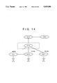
- the present invention is suitable for an AIN (Advanced Intelligent Network) system.
- the AIN system comprises a service control point and a plurality of service switching points, which are connected to the service control point via a signal transfer point.
- FIG. 14 is an AIN system, which comprises a service control point SCP, service switching points SSP, and a signal transfer point STP, which connects the service control point SCP and the service switching points SSP.
- the signal transfer point STP remote from the signal switching points SSP, is included in a common signal line network. Terminals are connected to the switching service points SSP. In FIG. 14, an end office, to which terminals are connected, is connected to one of the service switching points SSP.
- a service management system SMS is connected to the service control point SCP.
- the service control point SCP has a database commonly used for the service switching points SSP. Further, the service control point scP has a concentrated service control related to the service switching points SSP.
- the present invention is installed in the service control point SCP.
- the service switching point SSP When a terminal connected to one of the service switching points SSP generates a call, the service switching point SSP sends a request for call processing to the service control point SCP via the signal transfer point STP.
- the above request is applied to the processor 31 shown in FIG. 5, more particularly the call receiving unit 41 shown in FIG. 9.
- the network 30 shown in FIG. 5 or FIG. 9 corresponds to one of the service switching points SSP.
- the service control point SCP executes, fop example, the call accepting process, in which the service switching point or points SSP are controlled by the service control point SCP via the signal transfer point STP.
Landscapes
- Engineering & Computer Science (AREA)
- Signal Processing (AREA)
- Computer Networks & Wireless Communication (AREA)
- Exchange Systems With Centralized Control (AREA)
Applications Claiming Priority (4)
| Application Number | Priority Date | Filing Date | Title |
|---|---|---|---|
| JP3237727A JP2938630B2 (ja) | 1991-09-18 | 1991-09-18 | 複数の処理方法を有するシステムにおける負荷制御方式 |
| JP3-237727 | 1991-09-18 | ||
| JP3279299A JPH05145959A (ja) | 1991-10-25 | 1991-10-25 | 負荷制御処理量測定方法 |
| JP3-279299 | 1991-10-25 |
Publications (1)
| Publication Number | Publication Date |
|---|---|
| US5425086A true US5425086A (en) | 1995-06-13 |
Family
ID=26533340
Family Applications (1)
| Application Number | Title | Priority Date | Filing Date |
|---|---|---|---|
| US07/945,957 Expired - Lifetime US5425086A (en) | 1991-09-18 | 1992-09-16 | Load control system for controlling a plurality of processes and exchange system having load control system |
Country Status (2)
| Country | Link |
|---|---|
| US (1) | US5425086A (fr) |
| CA (1) | CA2078497C (fr) |
Cited By (30)
| Publication number | Priority date | Publication date | Assignee | Title |
|---|---|---|---|---|
| US5513255A (en) * | 1993-12-11 | 1996-04-30 | Electronics And Telecommunication Research Institute | Method for controlling overload of distributed processors of full electronic switching system |
| US5513257A (en) * | 1993-12-15 | 1996-04-30 | Electronics And Telecommunications Research Institute | Method for controlling overload in centralized and distributed operating hybrid switching system |
| WO1996015609A3 (fr) * | 1994-11-11 | 1996-08-08 | Nokia Telecommunications Oy | Prevention de la surcharge au niveau d'un n×ud de reseau de telecommunications |
| WO1996015634A3 (fr) * | 1994-11-11 | 1996-08-08 | Nokia Telecommunications Oy | Prevention de la surcharge au niveau d'un n×ud de reseau de telecommunications |
| US5550914A (en) * | 1994-02-25 | 1996-08-27 | Clarke; David A. | Communications signalling network apparatus |
| US5610915A (en) * | 1994-11-30 | 1997-03-11 | Mci Communications Corporation | System and method therefor of viewing call traffic of a telecommunications network |
| US5717745A (en) * | 1995-04-24 | 1998-02-10 | Mci Communications Corporation | System and method of efficiently evaluating different messages by a server in a telecommunications environment |
| US5802308A (en) * | 1995-04-20 | 1998-09-01 | Fujitsu Limited | Load control system for centralized management/control type network |
| WO1998057504A1 (fr) * | 1997-06-12 | 1998-12-17 | British Telecommunications Public Limited Company | Prevention contre la surcharge dans un point de commande de services (scp) |
| US5862204A (en) * | 1996-09-04 | 1999-01-19 | Electronics And Telecommunications Research Institute | Rare probability connection call registration method using incomplete call causation message for asynchronous transfer mode switching system |
| US5867565A (en) * | 1995-07-17 | 1999-02-02 | Fujitsu Limited | Intelligent network having service control node and service switching node for achieving traffic data collection processing |
| US5870460A (en) * | 1995-05-31 | 1999-02-09 | Mci Communications Corporation | System for least cost routing of data transactions in a telecommunications network |
| US5881140A (en) * | 1996-01-16 | 1999-03-09 | Dsc Telecom L.P. | Apparatus and method of determining switch utilization within a telecommunications network |
| WO1999030515A1 (fr) * | 1997-12-11 | 1999-06-17 | Telefonaktiebolaget Lm Ericsson (Publ) | Regulation de la charge et protection contre les surcharges pour systeme de communication temps reel |
| US5933481A (en) * | 1996-02-29 | 1999-08-03 | Bell Canada | Method of controlling call traffic in a telecommunication system |
| US5949862A (en) * | 1997-04-24 | 1999-09-07 | Fujitsu Limited | Traffic measuring apparatus and method |
| US6058412A (en) * | 1997-06-20 | 2000-05-02 | Fujitsu Limited | Service management system and process control system for intelligent network system |
| US6243735B1 (en) * | 1997-09-01 | 2001-06-05 | Matsushita Electric Industrial Co., Ltd. | Microcontroller, data processing system and task switching control method |
| US6252950B1 (en) * | 1998-09-30 | 2001-06-26 | Lucent Technologies Inc. | Predictive bursty real-time traffic control for telecommunications switching systems |
| US6389012B1 (en) * | 1997-10-17 | 2002-05-14 | Fujitsu Limited | Multi-processor system |
| US6421435B1 (en) * | 1998-11-30 | 2002-07-16 | Qwest Communications International Inc. | SS7 network planning tool |
| US20020159576A1 (en) * | 2001-04-25 | 2002-10-31 | Adams Richard Anthony | Method for overload control in a telecommunications network and apparatus therefor |
| WO2003047229A1 (fr) * | 2001-11-30 | 2003-06-05 | Telefonaktiebolaget Lm Ericsson (Publ) | Procede et disposition permettant le reglage de la charge d'un reseau |
| US6707900B1 (en) | 1996-07-19 | 2004-03-16 | Telefonaktiebolaget Lm Ericsson (Publ) | Dynamic load limiting |
| US20040066921A1 (en) * | 2002-10-02 | 2004-04-08 | Mohan Gawande | Network having space chattering control for maximizing call throughput during overload |
| US20060188079A1 (en) * | 2003-01-08 | 2006-08-24 | Jiashun Tu | Method of controlling the user calling load in soft switch system |
| WO2006120462A1 (fr) * | 2005-05-13 | 2006-11-16 | British Telecommunications Public Limited Company | Systeme de communication |
| US20070233603A1 (en) * | 2006-03-30 | 2007-10-04 | Schmidgall Matthew M | Flexible routing of electronic-based transactions |
| US20080175151A1 (en) * | 2005-05-13 | 2008-07-24 | British Telecommunications Public Limited Company | Communications System |
| US20120155297A1 (en) * | 2010-12-17 | 2012-06-21 | Verizon Patent And Licensing Inc. | Media gateway health |
Citations (3)
| Publication number | Priority date | Publication date | Assignee | Title |
|---|---|---|---|---|
| US4613729A (en) * | 1983-03-31 | 1986-09-23 | Siemens Aktiengesellschaft | Telecommunications system, particularly a telephone exchange system having overload-protected sequential logic systems |
| US4802205A (en) * | 1985-08-14 | 1989-01-31 | Siemens Aktiengesellschaft | Circuit arrangement for telecommunications switching systems, particularly for telephone switching systems comprising information-processing sequential logic systems and traffic measuring devices |
| US4984264A (en) * | 1989-02-22 | 1991-01-08 | Kabushiki Kaisha Toshiba | Call admission control method and cell flow monitoring method in the same method |
-
1992
- 1992-09-16 US US07/945,957 patent/US5425086A/en not_active Expired - Lifetime
- 1992-09-17 CA CA002078497A patent/CA2078497C/fr not_active Expired - Fee Related
Patent Citations (3)
| Publication number | Priority date | Publication date | Assignee | Title |
|---|---|---|---|---|
| US4613729A (en) * | 1983-03-31 | 1986-09-23 | Siemens Aktiengesellschaft | Telecommunications system, particularly a telephone exchange system having overload-protected sequential logic systems |
| US4802205A (en) * | 1985-08-14 | 1989-01-31 | Siemens Aktiengesellschaft | Circuit arrangement for telecommunications switching systems, particularly for telephone switching systems comprising information-processing sequential logic systems and traffic measuring devices |
| US4984264A (en) * | 1989-02-22 | 1991-01-08 | Kabushiki Kaisha Toshiba | Call admission control method and cell flow monitoring method in the same method |
Cited By (43)
| Publication number | Priority date | Publication date | Assignee | Title |
|---|---|---|---|---|
| US5513255A (en) * | 1993-12-11 | 1996-04-30 | Electronics And Telecommunication Research Institute | Method for controlling overload of distributed processors of full electronic switching system |
| US5513257A (en) * | 1993-12-15 | 1996-04-30 | Electronics And Telecommunications Research Institute | Method for controlling overload in centralized and distributed operating hybrid switching system |
| US5550914A (en) * | 1994-02-25 | 1996-08-27 | Clarke; David A. | Communications signalling network apparatus |
| US5898672A (en) * | 1994-11-11 | 1999-04-27 | Nokia Telecommunications Oy | Overload prevention in a telecommunication network node |
| WO1996015609A3 (fr) * | 1994-11-11 | 1996-08-08 | Nokia Telecommunications Oy | Prevention de la surcharge au niveau d'un n×ud de reseau de telecommunications |
| WO1996015634A3 (fr) * | 1994-11-11 | 1996-08-08 | Nokia Telecommunications Oy | Prevention de la surcharge au niveau d'un n×ud de reseau de telecommunications |
| US6018519A (en) * | 1994-11-11 | 2000-01-25 | Nokia Telecommunications Oy | Overload prevention in a telecommunications network node |
| US5610915A (en) * | 1994-11-30 | 1997-03-11 | Mci Communications Corporation | System and method therefor of viewing call traffic of a telecommunications network |
| US5802308A (en) * | 1995-04-20 | 1998-09-01 | Fujitsu Limited | Load control system for centralized management/control type network |
| US5717745A (en) * | 1995-04-24 | 1998-02-10 | Mci Communications Corporation | System and method of efficiently evaluating different messages by a server in a telecommunications environment |
| US5870460A (en) * | 1995-05-31 | 1999-02-09 | Mci Communications Corporation | System for least cost routing of data transactions in a telecommunications network |
| US5867565A (en) * | 1995-07-17 | 1999-02-02 | Fujitsu Limited | Intelligent network having service control node and service switching node for achieving traffic data collection processing |
| US5881140A (en) * | 1996-01-16 | 1999-03-09 | Dsc Telecom L.P. | Apparatus and method of determining switch utilization within a telecommunications network |
| US5933481A (en) * | 1996-02-29 | 1999-08-03 | Bell Canada | Method of controlling call traffic in a telecommunication system |
| US6707900B1 (en) | 1996-07-19 | 2004-03-16 | Telefonaktiebolaget Lm Ericsson (Publ) | Dynamic load limiting |
| US5862204A (en) * | 1996-09-04 | 1999-01-19 | Electronics And Telecommunications Research Institute | Rare probability connection call registration method using incomplete call causation message for asynchronous transfer mode switching system |
| US5949862A (en) * | 1997-04-24 | 1999-09-07 | Fujitsu Limited | Traffic measuring apparatus and method |
| WO1998057504A1 (fr) * | 1997-06-12 | 1998-12-17 | British Telecommunications Public Limited Company | Prevention contre la surcharge dans un point de commande de services (scp) |
| US6058412A (en) * | 1997-06-20 | 2000-05-02 | Fujitsu Limited | Service management system and process control system for intelligent network system |
| CN1096024C (zh) * | 1997-09-01 | 2002-12-11 | 松下电器产业株式会社 | 微控制器、数据处理系统及任务切换控制方法 |
| US6243735B1 (en) * | 1997-09-01 | 2001-06-05 | Matsushita Electric Industrial Co., Ltd. | Microcontroller, data processing system and task switching control method |
| US6389012B1 (en) * | 1997-10-17 | 2002-05-14 | Fujitsu Limited | Multi-processor system |
| WO1999030515A1 (fr) * | 1997-12-11 | 1999-06-17 | Telefonaktiebolaget Lm Ericsson (Publ) | Regulation de la charge et protection contre les surcharges pour systeme de communication temps reel |
| US6438551B1 (en) | 1997-12-11 | 2002-08-20 | Telefonaktiebolaget L M Ericsson (Publ) | Load control and overload protection for a real-time communication system |
| US6252950B1 (en) * | 1998-09-30 | 2001-06-26 | Lucent Technologies Inc. | Predictive bursty real-time traffic control for telecommunications switching systems |
| US6421435B1 (en) * | 1998-11-30 | 2002-07-16 | Qwest Communications International Inc. | SS7 network planning tool |
| US6826268B2 (en) * | 2001-04-25 | 2004-11-30 | Lucent Technologies Inc. | Method for overload control in a telecommunications network and apparatus therefor |
| US20020159576A1 (en) * | 2001-04-25 | 2002-10-31 | Adams Richard Anthony | Method for overload control in a telecommunications network and apparatus therefor |
| WO2003047229A1 (fr) * | 2001-11-30 | 2003-06-05 | Telefonaktiebolaget Lm Ericsson (Publ) | Procede et disposition permettant le reglage de la charge d'un reseau |
| US20050148337A1 (en) * | 2001-11-30 | 2005-07-07 | Bernt Karlsson | Method and arrangement for network load regulation |
| US7274780B1 (en) | 2002-10-02 | 2007-09-25 | At&T Corporation | Network having space chattering control for maximizing call throughput during overload |
| US20040066921A1 (en) * | 2002-10-02 | 2004-04-08 | Mohan Gawande | Network having space chattering control for maximizing call throughput during overload |
| US6829338B2 (en) * | 2002-10-02 | 2004-12-07 | At&T Corp. | Network having space chattering control for maximizing call throughput during overload |
| US6977995B1 (en) | 2002-10-02 | 2005-12-20 | At&T Corp. | Network having space chattering control for maximizing call throughput during overload |
| US20060188079A1 (en) * | 2003-01-08 | 2006-08-24 | Jiashun Tu | Method of controlling the user calling load in soft switch system |
| US7577242B2 (en) * | 2003-01-08 | 2009-08-18 | Zte Corporation | Method of controlling the user calling load in soft switch system |
| WO2006120462A1 (fr) * | 2005-05-13 | 2006-11-16 | British Telecommunications Public Limited Company | Systeme de communication |
| US20080175151A1 (en) * | 2005-05-13 | 2008-07-24 | British Telecommunications Public Limited Company | Communications System |
| US7933200B2 (en) | 2005-05-13 | 2011-04-26 | British Telecommunications Plc | Communications system |
| US8937871B2 (en) | 2005-05-13 | 2015-01-20 | British Telecommunications Plc | Communication system |
| US20070233603A1 (en) * | 2006-03-30 | 2007-10-04 | Schmidgall Matthew M | Flexible routing of electronic-based transactions |
| US20120155297A1 (en) * | 2010-12-17 | 2012-06-21 | Verizon Patent And Licensing Inc. | Media gateway health |
| US8717883B2 (en) * | 2010-12-17 | 2014-05-06 | Verizon Patent And Licensing Inc. | Media gateway health |
Also Published As
| Publication number | Publication date |
|---|---|
| CA2078497C (fr) | 1998-12-22 |
| CA2078497A1 (fr) | 1993-03-19 |
Similar Documents
| Publication | Publication Date | Title |
|---|---|---|
| US5425086A (en) | Load control system for controlling a plurality of processes and exchange system having load control system | |
| US6363052B1 (en) | Congestion control in network systems | |
| EP0791261B1 (fr) | Prevention de la surcharge au niveau d'un n ud de reseau de telecommunications | |
| US4907256A (en) | Exchange system having originating call restriction function | |
| US6826268B2 (en) | Method for overload control in a telecommunications network and apparatus therefor | |
| CA2024305C (fr) | Controle des surcharges dans les reseaux de communication | |
| US5778057A (en) | Service control point congestion control method | |
| AU678872B2 (en) | A method of controlling overloads in a telecommunications network | |
| JP3016811B2 (ja) | 総合サービス電気通信ネットワークのための予測性アクセス制御及び経路選択システム | |
| US4511762A (en) | Overload detection and control system for a telecommunications exchange | |
| EP0954934B1 (fr) | Reseau de telecommunications | |
| EP0791276B1 (fr) | Prevention de la surcharge dans un noeud de reseau de telecommunications | |
| US6532214B1 (en) | Controlling traffic congestion in intelligent electronic networks | |
| EP1389021A2 (fr) | Dispositif de détection d'un appel de masse et d'amélioration de ses effets | |
| US6970425B1 (en) | Method and apparatus for throttling and distributing data transmissions across a network | |
| JPH07203495A (ja) | 階層構造を有する分散交換システムの上位プロセッサー過負荷制御方法 | |
| US7139830B2 (en) | Communication apparatus and congestion regulation control method | |
| US6275572B1 (en) | Congestion control method and system in an exchange | |
| EP1880516B1 (fr) | Réseau de communication | |
| US6111854A (en) | Intelligent network congestion control system | |
| KR0170196B1 (ko) | 디지털 이동통신망 서비스 제어점의 과부하 제어 방법 | |
| JPH05145959A (ja) | 負荷制御処理量測定方法 | |
| JP2938630B2 (ja) | 複数の処理方法を有するシステムにおける負荷制御方式 | |
| KR960002679B1 (ko) | 지능망에서의 집중호 감시 및 제어 방법 | |
| JPH09130479A (ja) | Isdn交換機および、その輻輳制御方法 |
Legal Events
| Date | Code | Title | Description |
|---|---|---|---|
| AS | Assignment |
Owner name: FUJITSU LIMITED, JAPAN Free format text: ASSIGNMENT OF ASSIGNORS INTEREST.;ASSIGNORS:HIDAKA, TAKASHI;KANEKO, YOSHIHIRO;REEL/FRAME:006261/0451 Effective date: 19920910 |
|
| STCF | Information on status: patent grant |
Free format text: PATENTED CASE |
|
| FEPP | Fee payment procedure |
Free format text: PAYOR NUMBER ASSIGNED (ORIGINAL EVENT CODE: ASPN); ENTITY STATUS OF PATENT OWNER: LARGE ENTITY |
|
| FPAY | Fee payment |
Year of fee payment: 4 |
|
| FPAY | Fee payment |
Year of fee payment: 8 |
|
| FPAY | Fee payment |
Year of fee payment: 12 |