US5440074A - Method for producing a tight termination at the end of a shrinkable cable sleeve and a seal element used therewith - Google Patents
Method for producing a tight termination at the end of a shrinkable cable sleeve and a seal element used therewith Download PDFInfo
- Publication number
- US5440074A US5440074A US08/163,879 US16387993A US5440074A US 5440074 A US5440074 A US 5440074A US 16387993 A US16387993 A US 16387993A US 5440074 A US5440074 A US 5440074A
- Authority
- US
- United States
- Prior art keywords
- seal element
- cables
- seal
- fixing part
- cable sleeve
- Prior art date
- Legal status (The legal status is an assumption and is not a legal conclusion. Google has not performed a legal analysis and makes no representation as to the accuracy of the status listed.)
- Expired - Fee Related
Links
- 238000004519 manufacturing process Methods 0.000 title claims abstract description 6
- 239000000463 material Substances 0.000 claims abstract description 26
- 238000010438 heat treatment Methods 0.000 claims abstract description 4
- 238000007789 sealing Methods 0.000 claims description 90
- 238000000034 method Methods 0.000 claims description 34
- 230000001154 acute effect Effects 0.000 claims description 2
- 239000004020 conductor Substances 0.000 claims 1
- 239000002184 metal Substances 0.000 abstract description 2
- 230000008569 process Effects 0.000 description 10
- 230000004048 modification Effects 0.000 description 6
- 238000012986 modification Methods 0.000 description 6
- 239000000758 substrate Substances 0.000 description 6
- 230000006835 compression Effects 0.000 description 4
- 238000007906 compression Methods 0.000 description 4
- 238000003825 pressing Methods 0.000 description 4
- 239000003566 sealing material Substances 0.000 description 4
- 238000007493 shaping process Methods 0.000 description 4
- 239000004831 Hot glue Substances 0.000 description 3
- 238000009826 distribution Methods 0.000 description 3
- 239000003292 glue Substances 0.000 description 3
- 239000000565 sealant Substances 0.000 description 3
- 230000008901 benefit Effects 0.000 description 2
- 230000008602 contraction Effects 0.000 description 2
- 230000007246 mechanism Effects 0.000 description 2
- 239000000155 melt Substances 0.000 description 2
- 230000007480 spreading Effects 0.000 description 2
- 238000003892 spreading Methods 0.000 description 2
- 208000027418 Wounds and injury Diseases 0.000 description 1
- 238000010521 absorption reaction Methods 0.000 description 1
- 230000006978 adaptation Effects 0.000 description 1
- 230000004888 barrier function Effects 0.000 description 1
- 230000015572 biosynthetic process Effects 0.000 description 1
- 230000008859 change Effects 0.000 description 1
- 238000005253 cladding Methods 0.000 description 1
- 230000006378 damage Effects 0.000 description 1
- 230000001419 dependent effect Effects 0.000 description 1
- 230000000694 effects Effects 0.000 description 1
- 239000003779 heat-resistant material Substances 0.000 description 1
- 239000012943 hotmelt Substances 0.000 description 1
- 238000010348 incorporation Methods 0.000 description 1
- 238000007373 indentation Methods 0.000 description 1
- 208000014674 injury Diseases 0.000 description 1
- 230000013011 mating Effects 0.000 description 1
- 239000013589 supplement Substances 0.000 description 1
Images


Classifications
-
- H—ELECTRICITY
- H02—GENERATION; CONVERSION OR DISTRIBUTION OF ELECTRIC POWER
- H02G—INSTALLATION OF ELECTRIC CABLES OR LINES, OR OF COMBINED OPTICAL AND ELECTRIC CABLES OR LINES
- H02G15/00—Cable fittings
- H02G15/08—Cable junctions
- H02G15/18—Cable junctions protected by sleeves, e.g. for communication cable
- H02G15/1806—Heat shrinkable sleeves
-
- B—PERFORMING OPERATIONS; TRANSPORTING
- B29—WORKING OF PLASTICS; WORKING OF SUBSTANCES IN A PLASTIC STATE IN GENERAL
- B29C—SHAPING OR JOINING OF PLASTICS; SHAPING OF MATERIAL IN A PLASTIC STATE, NOT OTHERWISE PROVIDED FOR; AFTER-TREATMENT OF THE SHAPED PRODUCTS, e.g. REPAIRING
- B29C61/00—Shaping by liberation of internal stresses; Making preforms having internal stresses; Apparatus therefor
- B29C61/06—Making preforms having internal stresses, e.g. plastic memory
- B29C61/0608—Making preforms having internal stresses, e.g. plastic memory characterised by the configuration or structure of the preforms
- B29C61/0641—Clips for dividing preforms or forming branch-offs
-
- H—ELECTRICITY
- H02—GENERATION; CONVERSION OR DISTRIBUTION OF ELECTRIC POWER
- H02G—INSTALLATION OF ELECTRIC CABLES OR LINES, OR OF COMBINED OPTICAL AND ELECTRIC CABLES OR LINES
- H02G15/00—Cable fittings
- H02G15/013—Sealing means for cable inlets
-
- Y—GENERAL TAGGING OF NEW TECHNOLOGICAL DEVELOPMENTS; GENERAL TAGGING OF CROSS-SECTIONAL TECHNOLOGIES SPANNING OVER SEVERAL SECTIONS OF THE IPC; TECHNICAL SUBJECTS COVERED BY FORMER USPC CROSS-REFERENCE ART COLLECTIONS [XRACs] AND DIGESTS
- Y10—TECHNICAL SUBJECTS COVERED BY FORMER USPC
- Y10S—TECHNICAL SUBJECTS COVERED BY FORMER USPC CROSS-REFERENCE ART COLLECTIONS [XRACs] AND DIGESTS
- Y10S174/00—Electricity: conductors and insulators
- Y10S174/08—Shrinkable tubes
Definitions
- the present invention is directed to a method for producing a tight termination at an introduction region of a cable sleeve containing at least two cables and whose sleeve wall is shrinkable at least in the introduction region to produce a termination with the assistance of a sealing part of a seal element that is introduced between the cables and is at least partially composed of a heat-deformable material.
- Respective legs of the clamp lie on the outside sections of the sleeve allocated to one another and, as a result thereof, constrictions of the sleeve are produced, so to speak, between the substrates or cables. Problems during shrinking can occur in these constrictions between the substrates under certain circumstances when heat is non-uniformly applied, particularly, for example, given cables or substrates having extremely different diameters.
- German Patent 24 13 623 discloses an X-shaped termination member for sealing the gore regions or spaces in a cable sleeve. The seals in the gore region or the space between the cables being undertaken with these particular inserts.
- Pressing devices are likewise required here with which the envelope is pressed wave-shaped onto the terminating member lying therebetween so that a type of constriction also occurs here in every gore region.
- the pressing device in turn, has legs that lie on the outside lying opposite one another and in the valleys of the envelope formed by the termination member and, thus, press the envelope together wave-like dependent on the termination member.
- these pressing devices are replaced by U-shaped clamps after the shrinking and, likewise, lie against the outside of the envelope and securing the latter in position.
- An object of the present invention is to create a method for producing a tight termination in a cable sleeve having more than one cable introduction per introduction region, wherein the respective introduction region can be executed in a surveyable, optimally smooth and unproblematical shaping with employment of a simple seal element, wherein the seal element required for this purpose, as well as the termination produced therewith, are comprised by this object.
- the stated object is then achieved with a first method of the species initially cited in that the cable sleeve has its shrinkable region loosely wrapped around the introduction region, in that the seal element is fixed on one side between the cables with a fixing part of the seal element engaged on a sleeve wall of the cable sleeve and that subsequently heat is applied onto the region of the termination and onto the seal element until the heat-deformable seal part of the seal element is deformed so that it fills out the gore region between the introduced cables and the sleeve walls of the cable sleeve that lie opposite one another and have maximally shrunken to a tangential path between the cables in a sealing fashion.
- the stated object is also achieved in that the cable sleeve has its shrinkable region loosely wrapped around the introduction region and that the seal element has an outer fixing part of the seal element fixed between the cables to at least one of the cables and, subsequently, heat is applied onto the region of the termination and onto the seal element until the sealing part of the seal element arranged on an inner fixing part is deformed so that it will fill out the gore region between the introduced cables and the sleeve walls of the cable sleeve that lie opposite one another and have maximally shrunken down to a tangential course between the cables in a sealing fashion.
- a seal element for the first method wherein the seal element comprises an inner fixing part and an outer fixing part, in that the inner and the outer fixing pans are connected to one another at their ends that a longitudinally proceeding slot remains between the two fixing parts, wherein the nip of the slot corresponds to the thickness of the single sleeve wall of the cable sleeve, in that the seal element can be fixed onto the cable sleeve by introducing the sleeve wall into the slot and in that the inner fixing part comprises a sealing part composed of a material deformable under the application of heat.
- the seal element is created in conformity with the object which is characterized in that, with reference to the cable sleeve, it comprises an inner fixing part and outer fixing part and that the inner fixing part and the outer fixing part are connected lying behind one another in introduction direction and in that the outer fixing part can be fixed to at least one of the introduction cables with a fixing means and in that the inner fixing part comprises a seal part composed of a material deformable under the application of heat.
- the stated object is additionally achieved by a termination in the introduction region that is produced according to one of the methods upon employment of a corresponding seal element and that the seal element is formed by reshaping the sealing part contained in the seal element and formed of heat-deformable material during the shrinking process so that the course of the sleeve wall of the cable sleeve in the gore region between the two cables is, respectively, at most, tangential and in that the fixing part of the seal elements are arranged at one of the seal walls in the introduction region and/or at least one of the introduced cables.
- the goal of the invention is that the profilings, constrictions and the like disclosed in the prior art can be avoided in the introduction region of the cable sleeve having a plurality of cable introductions on the basis of the optimally simple shaping, as a result whereof the introduction region can be respectively considerably more reliably shaped.
- a formation of channels, waves or folds is no longer required for the introduction region having a plurality of cables of a cable sleeve, since these could lead to irregularities given incautious heat treatment.
- the cable sleeve is, therefore, no longer contracted between the introduced cables, but is now maximally shrunken to a tangential path between the cables.
- the sleeve wall between the two cables respectively forms the course of a common tangent so that no inwardly shaped portion of the cable sleeve walls are formed at the end of the shrinking process, since they are neither drawn inward nor pressed together from the outside.
- a seal element that is composed of a sealing part and of a fixing part is employed for the sealing of the gore region between the cables and the respective tangential course of the sleeve wall.
- the seal element is at least partially composed of a meltable material, for example of a known hot-melt adhesive, that, given the application of heat, which also causes the shrinking of the cable sleeve, are deformed such that the material melts and fills the gore region in sealing fashion on the basis of reshaping. Deformation thereby occurs due to the shrinking cable sleeve, which is maximally shrunken taut up to the tangential course of its walls between the cables.
- the sealing part of the seal element is fixed between the cables in a suitable way without the shrinking cable sleeve being performed by the seal element.
- the sealing part is connected to the correspondingly shaped fixing part that is either plugged onto the wall part of the cable sleeve between the cables at one side or is at least secured to one of the introduction cables.
- the fundamental position of the seal element is thereby prescribed without a deformation of the as yet unshrunken cable sleeve thereby occurring.
- the length of the inner fixing or, respectively, sealing parts is respectively optimum when it approximately corresponds to the diameter of the introduced cable; due, however, to the possibility of the emergence of excess material at the end face deviating up to 50% as definitely justifiable.
- At least the inner fixing part can be composed of a bimetallic fitting, or shaped part, which produces a desired modification of shape given the application of heat.
- the inner fixing part can also be provided with an indicator means for temperature, so that the point in time for ending the application of heat can, thus, be recognized.
- FIG. 1 is a longitudinal cross sectional view with portions in elevation of the positioning of a seal element in accordance with the present invention before shrinkage of the cable sleeve;
- FIG. 2 is a longitudinal cross sectional view of the device of FIG. 1 after the shrinking has occurred;
- FIG. 3 is a cross sectional view taken along the lines III--III of FIG. 1;
- FIG. 4 is a cross sectional view taken along the lines IV--IV of FIG. 2;
- FIG. 5 is a cross sectional view similar to FIG. 4 showing a triple introduction into the cable sleeve
- FIG. 6 is a cross sectional view similar to FIG. 4 showing a quadruple introduction with the assistance of two different sealing elements;
- FIG. 7 is a cross sectional view similar to FIG. 6 showing an introduction utilizing four identical sealing elements
- FIG. 8 is a cross sectional view similar to FIG. 4 showing a cable introduction having cables with different diameters
- FIG. 9 is a side view of a rigid seal element in accordance with the present invention.
- FIG. 10 is a cross sectional view similar to FIG. 5 showing a triple introduction with two different types of seal elements
- FIG. 11 is a cross sectional view similar to FIG. 4, wherein two seal elements were utilized in extending parallel to one another;
- FIG. 12 shows a seal element having an outer three-finger fixing part
- FIG. 13 is across sectional view similar to FIG. 3 before shrinking showing a seal part having a displaceable telescope-like arrangement
- FIG. 14 is a cross sectional view of the embodiment of FIG. 13 after shrinking
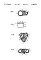
- FIG. 15 is a cross sectional view prior to assembly of a second exemplary embodiment of a seal element provided with a spreading arrangement
- FIG. 16 is the embodiment of FIG. 15 after shrinking
- FIG. 17 is a longitudinal cross sectional view prior to shrinking of an end of a cable sleeve having two seal elements which are movably connected by a web;
- FIG. 18 is a side view of a modification of the seal element employed in FIG. 17;
- FIG. 19 is a side view of two seal elements connected to one another by a pivot or articulation
- FIG. 20 is a side view of a modification of a seal element having a movable element
- FIG. 21 is a side view of a seal element wherein the seal parts can be spread
- FIG. 22 is another side view of a further exemplary embodiment of the seal element having an additional movable sealing part
- FIG. 23 is a side view of yet another exemplary embodiment having additional movable sealing parts
- FIG. 24 is a side view of a seal element having a shape of a figure seven;
- FIG. 25 is a side view of a seal element having an S shape
- FIG. 26 is a side view of two seal elements placed side-by-side and having a triangular sealing part
- FIG. 27 is a side view of two sealing elements placed side-by-side and having mating triangular sealing parts;
- FIG. 28 is a side view of a seal element wherein the seal part comprises a spring-like projection
- FIG. 29 is a plan view of a cable sleeve having a pair of cables introduced therein with a modification of a seal part;
- FIG. 30 is a longitudinal cross sectional view of a seal element if FIG. 29 likewise equipped with an auxiliary and having the arrangement as set forth hereinabove;
- FIG. 31 is a partial cross sectional view of the seal element utilized in the arrangement of FIG. 29;
- FIG. 32 is a cross sectional view with portions in elevation of a seal element usable in the arrangement of either FIG. 1 or FIG. 29;
- FIG. 33 is a cross sectional view of a sealing element having a molded or inner fixing part.
- the principles of the present invention are particularly useful when incorporated in a sealing element, generally indicated at 1 in FIG. 1.
- the sealing element 1 is introduced into an introduction region of a cable sleeve 2 for producing a tight termination according to the method of the present invention.
- the seal element 1 is composed of a thermally conductive fixing part 3, 4 and of a sealing part 6, wherein the sealing part is preferably composed of a meltable material, such as, for example, a hot melt adhesive.
- the fixing part 3, 4, is composed of a heat-resistant material, preferably metal.
- the fixing part 3, 4 has a U-shaped clip-like shape and contains a slot 5 extending in a longitudinal direction between the portion 3 and portion 4.
- the gap width of the slot 5 corresponds to the order of magnitude of the wall thickness of the cable sleeve 2 and forms means for fixing the element 1 to the cable sleeve 2.
- this clip-like fixing part 3, 4 is introduced between the cables 3 in the gore region formed together with the cable sleeve 2 so that a wall of the cable sleeve 2 is plugged up to the base of the slot 5 of the part 3, 4.
- the introduction region is still completely loose, as best illustrated in FIG. 3.
- Shaping measures, such as constrictions or folding or fixing of the sleeve walls are, thus, not necessary.
- the inwardly disposed fixing part 4 of the fixing part 3, 4 is the carrier of the sealing part 6 at the same time.
- the sealing part 6 is dimensioned so that in terms of the quantity of meltable material that at least the gore region between the cables 7 and the sleeve wall that maximally proceed tangentially between the cables 7 is filled out in a sealing fashion, and this maximally tangential course of the seal wall of the cable sleeve 1 in the gore region forms by itself during shrinking when care is not exercised to see that the emergence of the molten sealing material of the part 6 on the face end is prevented. Otherwise, the sealing part 6 is deformed until the gore region is completely tightly molded. An emergence of excess material of the sealing part at the end face is thereby also possible.
- the cable sleeve 2 has a smooth, uniform surface so that no warping or irregularities can occur in this introduction region which would lead to difficulties with respect to tightness.
- the cable sleeve 2 is still loosely placed around the cables 7. This can thereby be a matter of a tubular cable sleeve or a cable collar having a longitudinal closure of shrinkable material, which is not shown in the drawings.
- the seal element 1, together with its fixing parts 3, 4 has merely been slipped onto the sleeve wall of the cable sleeve 2 so that the outer fixing part 3 presses against the outside and the inner fixing part 4 of the seal element presses against the inside of the cable sleeve.
- the inner fixing part 4 is surrounded by the actual sealing material of the sealing part 6.
- the cable sleeve 2 has maximally shrunken to the tangential path or course between the enclosed cables 7.
- the core region is completely filled up with the deformable sealing material of the part 6 and forms the tight termination in the introduction region between the introduction cable 7 and the tangentially proceeding sleeve walls of the cable sleeve 2.
- a let-in portion, constriction or wave-shaped bent portions of the sleeve wall parts of the cable sleeve 2 between the cables 7 has not occurred in the gore region, so that the risk of jeopardizing deformation is no longer present at this introduction region.
- three seal elements 1 can be introduced between adjacent cables, with one between each pair of adjacent cable, so that after shrinking, the arrangement of FIG. 5 will be obtained.
- the cables are arranged in a triangular position and the three seal elements are introduced lying therebetween, and these seal parts 6 will melt together to form a single tight termination.
- the course of the cable walls of the cable sleeve between the individual cables 7 is, respectively, tangential. Indentations or wave-shapes, drawn-in courses of the cable sleeve walls are likewise not produced, since the contraction due to the seal elements has not occurred.
- a triple or multiple introduction of the cables can also be produced by cables 7 introduced in parallel, wherein one seal element must then be introduced between, respectively, two neighboring cables.
- FIG. 6 shows a quadruple introduction of cables 7, wherein the cables are arranged in the corners of a quadrilateral shape.
- the inner space which occurs is prepared with the assistance of one long seal element and two short seal elements in a way set forth wherein the long seal element 1b has its inner fixing part 4b extending transversely through the interspace between the four cables with two cables on one side and two cables on the other side.
- the course of the shrunken sleeve wall between, respectively, two cables is also tangential.
- FIG. 7 can be used, wherein four identical seal elements 1a, wherein the inwardly directed pans 4, the seal elements 1a, respectively, extend not entirely up to the middle of the tight termination.
- the sealing parts 6 are deformed during shrinkage that the entire gore region is filled with the sealing fashion.
- the fixing part 3 lying against the sleeve wall of the cable sleeve 2 on the outside is respectively fashioned broader than the inwardly disposed fixing part 4, as a result whereof the absorption and, thus, the delivery of the heat into the interior is promoted.
- FIG. 8 illustrates an arrangement of the cables 7 at a cable introduction, wherein the diameters of the cables 7 are different.
- the obliquely dropping-off form of the sleeve wall will occur in the introduction region of the cable sleeve 2; however, a maximum tangential course of the cable sleeve wall between the individual cables 7 is also, again, created in turn.
- the seal element 1, that is again fixed on only one sleeve wall here, has its inner fixing part 4, again, projecting into the inside of the gore region wherein the sealing part 6 has already been reshaped to form the tight enclosure.
- the outer fixing part 3 has its free end bent up so that it can be slipped onto the sleeve wall better. Moreover, two notches or transverse riflings or grooves 8 may be seen, and these prevent the seal element 1 from sliding off the end of the sleeve. As a result thereof, less pressure is exerted in these notch regions and, moreover, a thicker layer of hot-melt adhesive respectively occurs on the inside of the sleeve wall, so to speak as a glue reservoir. This forms a better sealing barrier in the glue regions that have been thinned by the pressure of the seal element.
- the inner fixing part 4 of the seal element 1 is provided with the actual sealing part 6 in the form of a sealant that melts given the application of heat.
- FIG. 10 A version of the triple introduction of cables 7 is illustrated in FIG. 10.
- a normal seal element 1 a having a short inner fixing part 4 is used, and this extends approximately up to the middle of the termination.
- a fixing part 4c of a second seal element 1c is fashioned longer and is in an angled-off or bent condition. This element 1c is introduced so that a distribution of the seal material 6 into the two gore regions can thereby occur.
- the outer fixing parts 3 are, again, thickened, for example rounded off, to avoid injury.
- More than one seal element 1 can be introduced as needed in the gore region between the cables 7 and the sleeve walls, as illustrated in FIG. 11.
- the maximally tangential course of the sleeve walls of the cable sleeve 2 occurs between the cable 7 after the shrinking process, since the seal element 1 also does not provide any contraction of the sleeve wall here.
- Such an arrangement is expedient, for example, when the cables 7 lie at a greater distance from one another and when the sealing part 6 of the single seal element 1 could then potentially be too narrowly dimensioned.
- a seal element 1d is illustrated in FIG. 12 and has an outwardly disposed fixing part 3d which is fashioned in a multi-finger form. The stability of the fixing is thereby enhanced and the sleeve wall that is clamped is also more uniformly heated during the shrinking process.
- a seal element 1e is illustrated and has an inner fixing part 4e which is adjustable so that it can have the extent of its depth matched to the height of the gore region.
- a telescope-like embodiment is selected and the inner fixing part 4e is initially extremely long, for example the situation can be such that the cable sleeve walls of the cable sleeve 2 are spread in the gore region.
- the movable telescoping part also carries the sealing part 6 in the form of a material that can be reshaped given the application of heat.
- the seal element is constructed telescope-like and a maximum tangential course of the cable sleeve 2, again, occurs between the cables 7 in the introduction region of the cable sleeve 2.
- the reshaped sealing part 6 will fill the gore region in a sealing fashion.
- FIG. 15 An exemplary embodiment of the seal element 1f is illustrated in FIG. 15 and has an inner fixing part 4f that will vary given an application of heat.
- a compression spring element 9 is inserted in the inner fixing part 4f, and this is held, for example, in its compressed condition when delivered.
- the interlock for example a hot-melt glue
- the inner fixing part 4f spreads open due to the spring power of the compression spring 9. This additionally contributes to the distribution of the molten sealing part 6 in the gore region.
- the movable fixing part 4f has been driven outward by the compression spring 9 during the shrinking process.
- the movable fixing part will displace a volume of corresponding sealant in the gore region and, thus, contributes to an improved distribution thereof.
- FIG. 17 an exemplary embodiment for the termination of the introduction region of a cable sleeve is illustrated, wherein two seal elements 1 of the type set forth above are movably independent of one another via a common web 10.
- the web 10 is in the inside of the gore region and allows the position of the two seal elements to slip onto the sleeve wall of the cable sleeve to be adjusted nearly independent of one another. This facilitates mounting, particularly when the cable sleeve 2 has a conical taper, as shown in the Figure.
- the outer fixing part 3 of the seal element 1 comes to lie at the outside of the sleeve wall lying opposite one another, whereby the mobility of the seal elements 2 here also produce a maximally tangential course of the sleeve walls in the gore region.
- the inner fixing parts 4 each respectively carry the sealing parts 6 of an adequate quantity of meltable material.
- FIG. 18 shows a seal element composed of two seal elements 1, similar to that utilized in the embodiment of FIG. 17. These two seal elements 1 are movably connected to one another by a web 10.
- the inner fixing parts 4 are each respectively provided with the sealing parts 6 of heat-deformable material.
- the outer fixing parts 3 lie outside the tight termination of the cable sleeve walls, without indented portion or inwardly directed deformations occurring.
- FIG. 19 likewise, shows an exemplary embodiment of a combined sealing element having two individual seal elements 1 held in mobile fashion relative to one another.
- the two seal elements 1 are connected to one another by an articulation or pivot 11.
- the inner fixing part 4 is provided with a meltable sealing part 6 of deformable material for each of the two seals.
- FIG. 20 Another version of the seal element 1 is illustrated in FIG. 20 and has a movable fixing and sealing part 12 that is movably arranged via an articulation or pivot 13 to the inner fixing part 4 of the seal element 1.
- This arrangement has the advantage that the overall width of the sealing parts 6 and 12 can be adapted during the shrinking to conform to the shaping of the gore region, first due to the angling of the mobile sealing part 12 and, second, due to the deformable sealing material of the sealing parts 6.
- FIG. 21 another embodiment of the seal element, wherein the sealing part 6 enlarges during heating, for example, as in the exemplary embodiment of FIGS. 15 and 16.
- an element 14 can shift relative to the base 4.
- FIG. 22 A seal element having a movable part similar to that of FIG. 20, is illustrated in FIG. 22, wherein an articulation 16 is utilized for the mobility of an additional fixing and sealing part 15 which is arranged at the free end of the inner fixing part 4.
- the seal part 6 can also extend over the fixing pan 4 and over the additional fixing part 15, wherein the mobility is then frozen in at normal temperatures.
- the desired direction of movement of the mobile sealing part 15 can be additionally promoted, for example a spreading or a retraction.
- the effect of the spring element can, likewise, be frozen in by the material of the sealing part 6.
- the inner fixing part 4 of the seal element in the exemplary embodiment of FIG. 23 additionally has a vertically angled portion or nose 18 so that it can already by employed for relatively wide gore regions in its original condition.
- the movable part 17 serves the purpose of further adaptation of the sealing regions of the termination. The other conditions, such as the presence of a spring, have already been described.
- the inner fixing part 4 of the seal element 1 is provided with a continuation 19 that can be fashioned either rigid, resilient or plastically deformable.
- a seal element can be employed in the same way as set forth above.
- an element 1 having an S shape whereby the inner S shape projection 20 can again be rigid, resilient or plastically deformable.
- FIG. 26 To form a tight termination with the assistance of two identically constructed seal elements 1, an arrangement of elements 1 is shown in FIG. 26.
- the two elements are respectively composed of fixing pans 3-4, as already mentioned.
- the inner fixing part not visible respectively carries the seal part 6 that has a triangular shape and are each respectively mounted on a sleeve wall by being introduced with the points directed toward one another.
- the sealing parts 6 are deformed and move toward one another and fuse to form a tight termination.
- the course of the sleeve walls between the individual cables is again, at most, tangential.
- FIG. 27 an arrangement with two similar seal parts is illustrated, wherein the sealing part 6 has a triangular configuration.
- the two sealing pans supplement one another to form a block and fuse together during the shrinking process to form a tight termination.
- FIG. 28 Another embodiment of the seal element 1 is illustrated in FIG. 28 and shows an acute continuation 21 on the inner fixing part 4, which allows a change in shape and, thus, a shape matching.
- the entire inner structure can be coated with a sealing part 6 in the form of deformable material.
- the member 1 was attached to an edge of the sealing sleeve.
- FIG. 29 Another embodiment is illustrated in FIG. 29, wherein a sealing element 22 is not physically attached to the cable sleeve, but is connected to at least one of the introduction cables 7 between which it is introduced.
- the cable sleeve 2 is thus arranged completely freely around the introduction region and can be shrunk without impediment.
- the ultimate course of the cable sleeve walls of the cable sleeve 2 between the cable 7 can likewise, again, only be tangential at the most, whereas the sealing part 6 of the sealing element 22, which is fixed to the cable 7, is again deformed due to the shrinking cable sleeve 2 so that a tight termination occurs in the introduction region.
- the conditions of the sealing part 6 are absolutely comparable to those of the preceding exemplary embodiments.
- the sole difference lies in that the fixing part 23 proceeds in the same direction as the inner fixing part 4 coated with the sealing part 6 and that the appropriate fixing means 24, for example a strap retainer or similar mechanism, is arranged at the fixing part 23 for connecting the seal element to one or more of the cables.
- the seal element is then secured to at least one of the introduction cables 7 with these fixing means 24.
- the seal part 6 is likewise dimensioned so that in terms of quantity of sealant that the latter is adequate for a tight termination in any case.
- the inner portion 4 and the portion 6 can have the various arrangements previously described.
- An example is shown in FIG. 30 wherein an inner fixing part 26 has an additional movable fixing part 25 that is seated via an articulation 27 on the inner fixing part 26 of the seal element 22.
- the fixing parts 26 and 27 are coated or, respectively, surrounded with a sealing part 6 composed of appropriately deformable material.
- the mobile sealing part 25 is correspondingly pressed on and together with the fixing sealing part 26 and the seal part 6 to form an entire termination in the introduction region of the cable sleeve 2.
- Two mobile sealing pans 28 can also be secured to a sealing part 29, as illustrated in FIG. 31. Matching in the introduction region can likewise be achieved in this way, since the two sealing parts 28, together with the deformable sealing parts 6, are pressed into their ultimate position by the shrinking cable sleeve 2.
- the sealing member or part was either connected to the cable sleeve or to the cables.
- parts 30, 31 are combined so that it can be fixed to both.
- a fixing part 30 is continued farther in the longitudinal direction of the inner fixing part 32 so that it can be affixed to at least one of the cables.
- an outer fixing part 31 is also provided and coacts with the inner fixing part 32 to form a slot 34 for receiving the cable sleeve 2. In this way, two fixings can now be undertaken, one to the cable sleeve 2 and then to at least one of the cables that is being introduced.
- the arrangement is shown with a movable part 33 which receives the material or part 6.
- the inner fixing pan 4 whether movable or not, comprises at least one shaped portion 35 at the free, lower end, and this shaped portion 35 is formed, for example, on both sides.
- the seal element 1 can no longer slip out of the interspace between the two cables after the introduction on the sleeve wall.
- Such formed portions can also be provided in all of the previous exemplary embodiments of the seal elements.
- a plurality of inner fixing parts that can also be movable, moreover, can be arranged on this outer fixing part.
Landscapes
- Cable Accessories (AREA)
Applications Claiming Priority (2)
| Application Number | Priority Date | Filing Date | Title |
|---|---|---|---|
| DE4241304.4 | 1992-12-08 | ||
| DE4241304 | 1992-12-08 |
Publications (1)
| Publication Number | Publication Date |
|---|---|
| US5440074A true US5440074A (en) | 1995-08-08 |
Family
ID=6474695
Family Applications (1)
| Application Number | Title | Priority Date | Filing Date |
|---|---|---|---|
| US08/163,879 Expired - Fee Related US5440074A (en) | 1992-12-08 | 1993-12-08 | Method for producing a tight termination at the end of a shrinkable cable sleeve and a seal element used therewith |
Country Status (6)
| Country | Link |
|---|---|
| US (1) | US5440074A (da) |
| EP (1) | EP0601464B1 (da) |
| AT (1) | ATE149271T1 (da) |
| DE (1) | DE59305534D1 (da) |
| DK (1) | DK0601464T3 (da) |
| ES (1) | ES2099355T3 (da) |
Cited By (3)
| Publication number | Priority date | Publication date | Assignee | Title |
|---|---|---|---|---|
| US5792989A (en) * | 1996-11-12 | 1998-08-11 | Minnesota Mining And Manufacturing Company | Wrap type cable closure end seal |
| CN102832469A (zh) * | 2011-06-17 | 2012-12-19 | 矢崎总业株式会社 | 电缆连接端子与具有该电缆连接端子的线束 |
| US10319497B2 (en) * | 2015-07-10 | 2019-06-11 | Autonetworks Technologies, Ltd. | Molded portion-equipped electric cable and method for manufacturing molded portion-equipped electric cable |
Citations (16)
| Publication number | Priority date | Publication date | Assignee | Title |
|---|---|---|---|---|
| DE2413623A1 (de) * | 1974-03-21 | 1975-10-02 | Rose Walter Kg | Kabelmuffe fuer den anschluss von mindestens zwei zueinander parallelen kabeln |
| DE2900518A1 (de) * | 1978-01-09 | 1979-07-19 | Raychem Sa Nv | Verfahren zur bildung einer dichten abzweigenden verbindung und zur durchfuehrung des verfahrens bestimmte klammer |
| DE3105471A1 (de) * | 1981-02-14 | 1982-09-02 | Walter Rose Gmbh & Co Kg, 5800 Hagen | "vorrichtung zur verklammerung der endbereiche eines die aussenumhuellung einer kabelmuffe bildenden schrumpffaehigen kunststoffschlauches" |
| DE3204866A1 (de) * | 1982-02-11 | 1983-08-18 | Siemens AG, 1000 Berlin und 8000 München | Kabelmuffe mit fuellstueck im einfuehrungsbereich |
| US4400579A (en) * | 1978-01-09 | 1983-08-23 | N.V. Raychem S.A. | Branch-off assembly |
| US4438294A (en) * | 1981-02-11 | 1984-03-20 | Siemens Aktiengesellschaft | Cable sleeve with an entrance socket of shrinkable material |
| DE8414101U1 (de) * | 1984-05-09 | 1984-09-06 | Walter Rose Gmbh & Co Kg, 5800 Hagen | Vorrichtung zum Anbringen eines Elementes aus Heißschmelzkleber an einem Kunststoffschlauch |
| US4590328A (en) * | 1983-03-22 | 1986-05-20 | Siemens Aktiengesellschaft | Plastic sealing plugs for cable fittings |
| US4680065A (en) * | 1984-01-10 | 1987-07-14 | Raychem Corporation | Branch-off technique |
| US4689474A (en) * | 1983-05-26 | 1987-08-25 | N.V. Raychem S.A. | Electrically heat-recoverable sleeve |
| GB2195840A (en) * | 1986-10-02 | 1988-04-13 | Egerton A C Ltd | Plug for retaining and sealing cables |
| DE3728638A1 (de) * | 1987-08-27 | 1989-03-09 | Stewing Gmbh & Co Kg | Abzweigklammer fuer waermeschrumpffaehiges muffengehaeuse |
| DE3815027A1 (de) * | 1988-05-03 | 1989-11-16 | Rxs Schrumpftech Garnituren | Klammer zur bildung eines abzweigs bei schrumpfbaren kabelmuffen |
| US4920236A (en) * | 1986-10-24 | 1990-04-24 | Fujikura Ltd. | Sealing cable junctions |
| US5278355A (en) * | 1989-07-20 | 1994-01-11 | Raychem Limited | Environmental sealing |
| US5317797A (en) * | 1990-01-12 | 1994-06-07 | Raychem Corporation | Method of enclosing a substrate within a heat-shrinkable sleeve |
-
1993
- 1993-12-01 AT AT93119381T patent/ATE149271T1/de not_active IP Right Cessation
- 1993-12-01 ES ES93119381T patent/ES2099355T3/es not_active Expired - Lifetime
- 1993-12-01 DK DK93119381.7T patent/DK0601464T3/da active
- 1993-12-01 EP EP93119381A patent/EP0601464B1/de not_active Expired - Lifetime
- 1993-12-01 DE DE59305534T patent/DE59305534D1/de not_active Expired - Fee Related
- 1993-12-08 US US08/163,879 patent/US5440074A/en not_active Expired - Fee Related
Patent Citations (19)
| Publication number | Priority date | Publication date | Assignee | Title |
|---|---|---|---|---|
| DE2413623A1 (de) * | 1974-03-21 | 1975-10-02 | Rose Walter Kg | Kabelmuffe fuer den anschluss von mindestens zwei zueinander parallelen kabeln |
| US4648924A (en) * | 1978-01-09 | 1987-03-10 | N.V. Raychem S.A. | Branch-off method |
| DE2900518A1 (de) * | 1978-01-09 | 1979-07-19 | Raychem Sa Nv | Verfahren zur bildung einer dichten abzweigenden verbindung und zur durchfuehrung des verfahrens bestimmte klammer |
| US4298415A (en) * | 1978-01-09 | 1981-11-03 | N.V. Raychem S.A. | Branch-off method |
| US4400579A (en) * | 1978-01-09 | 1983-08-23 | N.V. Raychem S.A. | Branch-off assembly |
| US4734543A (en) * | 1978-01-09 | 1988-03-29 | Nolf Jean Marie E | Branch-off assembly |
| US4438294A (en) * | 1981-02-11 | 1984-03-20 | Siemens Aktiengesellschaft | Cable sleeve with an entrance socket of shrinkable material |
| DE3105471A1 (de) * | 1981-02-14 | 1982-09-02 | Walter Rose Gmbh & Co Kg, 5800 Hagen | "vorrichtung zur verklammerung der endbereiche eines die aussenumhuellung einer kabelmuffe bildenden schrumpffaehigen kunststoffschlauches" |
| DE3204866A1 (de) * | 1982-02-11 | 1983-08-18 | Siemens AG, 1000 Berlin und 8000 München | Kabelmuffe mit fuellstueck im einfuehrungsbereich |
| US4590328A (en) * | 1983-03-22 | 1986-05-20 | Siemens Aktiengesellschaft | Plastic sealing plugs for cable fittings |
| US4689474A (en) * | 1983-05-26 | 1987-08-25 | N.V. Raychem S.A. | Electrically heat-recoverable sleeve |
| US4680065A (en) * | 1984-01-10 | 1987-07-14 | Raychem Corporation | Branch-off technique |
| DE8414101U1 (de) * | 1984-05-09 | 1984-09-06 | Walter Rose Gmbh & Co Kg, 5800 Hagen | Vorrichtung zum Anbringen eines Elementes aus Heißschmelzkleber an einem Kunststoffschlauch |
| GB2195840A (en) * | 1986-10-02 | 1988-04-13 | Egerton A C Ltd | Plug for retaining and sealing cables |
| US4920236A (en) * | 1986-10-24 | 1990-04-24 | Fujikura Ltd. | Sealing cable junctions |
| DE3728638A1 (de) * | 1987-08-27 | 1989-03-09 | Stewing Gmbh & Co Kg | Abzweigklammer fuer waermeschrumpffaehiges muffengehaeuse |
| DE3815027A1 (de) * | 1988-05-03 | 1989-11-16 | Rxs Schrumpftech Garnituren | Klammer zur bildung eines abzweigs bei schrumpfbaren kabelmuffen |
| US5278355A (en) * | 1989-07-20 | 1994-01-11 | Raychem Limited | Environmental sealing |
| US5317797A (en) * | 1990-01-12 | 1994-06-07 | Raychem Corporation | Method of enclosing a substrate within a heat-shrinkable sleeve |
Cited By (6)
| Publication number | Priority date | Publication date | Assignee | Title |
|---|---|---|---|---|
| US5792989A (en) * | 1996-11-12 | 1998-08-11 | Minnesota Mining And Manufacturing Company | Wrap type cable closure end seal |
| CN102832469A (zh) * | 2011-06-17 | 2012-12-19 | 矢崎总业株式会社 | 电缆连接端子与具有该电缆连接端子的线束 |
| US20120318575A1 (en) * | 2011-06-17 | 2012-12-20 | Yazaki Corporation | Electric cable connection terminal and wire harness having the electric cable connection terminal |
| CN102832469B (zh) * | 2011-06-17 | 2015-11-11 | 矢崎总业株式会社 | 电缆连接端子与具有该电缆连接端子的线束 |
| US9780460B2 (en) * | 2011-06-17 | 2017-10-03 | Yazaki Corporation | Electric cable connection terminal and wire harness having the electric cable connection terminal |
| US10319497B2 (en) * | 2015-07-10 | 2019-06-11 | Autonetworks Technologies, Ltd. | Molded portion-equipped electric cable and method for manufacturing molded portion-equipped electric cable |
Also Published As
| Publication number | Publication date |
|---|---|
| DE59305534D1 (de) | 1997-04-03 |
| ATE149271T1 (de) | 1997-03-15 |
| DK0601464T3 (da) | 1997-07-28 |
| EP0601464B1 (de) | 1997-02-26 |
| ES2099355T3 (es) | 1997-05-16 |
| EP0601464A1 (de) | 1994-06-15 |
Similar Documents
| Publication | Publication Date | Title |
|---|---|---|
| US4438294A (en) | Cable sleeve with an entrance socket of shrinkable material | |
| US5810825A (en) | Surgical wire clamp | |
| US4693767A (en) | Cable sleeve with a device cross-shaped in cross-section for support of cable ends entering the cable sleeves | |
| US4388488A (en) | Sealing system for a longitudinally divided cable fitting element | |
| US5399811A (en) | Device for sealing cables entering a cable coupling sleeve | |
| JPH0135569B2 (da) | ||
| CA1302530C (en) | Sealing cable junctions | |
| US3383769A (en) | Lance matrix band clamp for dental purposes | |
| KR100228932B1 (ko) | 케이블 분기부를 밀폐시키기 위한 장치 및 치수복원성 슬리브 | |
| US4203000A (en) | Cable sleeve assembly | |
| US5440074A (en) | Method for producing a tight termination at the end of a shrinkable cable sleeve and a seal element used therewith | |
| JPH0345612B2 (da) | ||
| US4413922A (en) | Branch-off seal | |
| US5545851A (en) | Cap sleeve | |
| EP0379635A1 (de) | Wärmeisoliertes Verbindungs- oder Verteilerstück für beheizbare Schläuche | |
| US4714277A (en) | Longitudinally divided sleeve of shrinkable material | |
| US4346258A (en) | Cable sleeve sealed at each end by end members | |
| EP0857562B1 (de) | Schrumpfkappe und Verfahren zu ihrer Herstellung sowie mit der Schrumpfkappe versehenes Bauteil | |
| EP2897778A1 (de) | Verfahren zur herstellung eines kabelsatzes sowie kabelsatz | |
| JP2667259B2 (ja) | ケーブル接続部の密封用スペーサ | |
| CA1264912A (en) | Longitudinally divided sleeve of shrinkable material | |
| GB1585154A (en) | Heat recoverable article | |
| EP0439284A1 (en) | Cable closure | |
| GB2061025A (en) | Material for wrapping around pipe, cable or the like | |
| CA2046497A1 (en) | Cable closure |
Legal Events
| Date | Code | Title | Description |
|---|---|---|---|
| AS | Assignment |
Owner name: RXS SCHRUMPFTECHNIK-GARNITUREN, GMBH, GERMANY Free format text: ASSIGNMENT OF ASSIGNORS INTEREST;ASSIGNORS:MELTSCH, HANS-JUERGEN;SCHULTE, WOLFGANG;REEL/FRAME:006861/0641 Effective date: 19931210 |
|
| FEPP | Fee payment procedure |
Free format text: PAYOR NUMBER ASSIGNED (ORIGINAL EVENT CODE: ASPN); ENTITY STATUS OF PATENT OWNER: LARGE ENTITY |
|
| FPAY | Fee payment |
Year of fee payment: 4 |
|
| FEPP | Fee payment procedure |
Free format text: PAYER NUMBER DE-ASSIGNED (ORIGINAL EVENT CODE: RMPN); ENTITY STATUS OF PATENT OWNER: LARGE ENTITY |
|
| REMI | Maintenance fee reminder mailed | ||
| LAPS | Lapse for failure to pay maintenance fees | ||
| FP | Lapsed due to failure to pay maintenance fee |
Effective date: 20030808 |
|
| STCH | Information on status: patent discontinuation |
Free format text: PATENT EXPIRED DUE TO NONPAYMENT OF MAINTENANCE FEES UNDER 37 CFR 1.362 |