US5456015A - Construction framing square - Google Patents
Construction framing square Download PDFInfo
- Publication number
- US5456015A US5456015A US08/163,881 US16388193A US5456015A US 5456015 A US5456015 A US 5456015A US 16388193 A US16388193 A US 16388193A US 5456015 A US5456015 A US 5456015A
- Authority
- US
- United States
- Prior art keywords
- edge
- square
- width
- base
- edges
- Prior art date
- Legal status (The legal status is an assumption and is not a legal conclusion. Google has not performed a legal analysis and makes no representation as to the accuracy of the status listed.)
- Expired - Lifetime
Links
Images



Classifications
-
- B—PERFORMING OPERATIONS; TRANSPORTING
- B25—HAND TOOLS; PORTABLE POWER-DRIVEN TOOLS; MANIPULATORS
- B25H—WORKSHOP EQUIPMENT, e.g. FOR MARKING-OUT WORK; STORAGE MEANS FOR WORKSHOPS
- B25H7/00—Marking-out or setting-out work
-
- G—PHYSICS
- G01—MEASURING; TESTING
- G01B—MEASURING LENGTH, THICKNESS OR SIMILAR LINEAR DIMENSIONS; MEASURING ANGLES; MEASURING AREAS; MEASURING IRREGULARITIES OF SURFACES OR CONTOURS
- G01B3/00—Measuring instruments characterised by the use of mechanical techniques
- G01B3/56—Gauges for measuring angles or tapers, e.g. conical calipers
- G01B3/566—Squares
Definitions
- This invention is related in general to framing tools, and more particularly, to layout squares for determining the reference points and lines during rafter construction and the layout of conventional stud walls, caps and the like.
- the aforementioned dimension of the endpiece prevents the device from being laid flat across the width of a board that is 11/2" thick unless the board is put on edge or elevated off a flat surface.
- This device does not provide a means of attaching a conventional tape measure for the quick referencing and marking of material over extended distances.
- this device with its adapter is cumbersome, it requires assembly by the user and it does not lend itself to economic production.
- the improved device of the present invention satisfies the forgoing needs. Accordingly, it is an object of the present invention generally to overcome the difficulties and disadvantages of the prior art discussed above.
- the preferred embodiment of the present invention is a layout square having a rectangular base with opposing parallel faces having a first edge and second edge disposed at a right angle.
- the length of the second edge is dimensioned to cover not less than the width of two pieces of material laid side by side and the length of the first edge is proximate the thickness of three pieces of material laid together on edge.
- the base is provided with subsequent edges that extend parallel to the bases second edge and their lengths are proximate the length of the base. These edges are parallel to the second edge of the base and spaced substantially equal to the thickness of a piece of material from each other.
- a guide is integrally connected on one end of the base along the first edge and is perpendicular to the base.
- the guide extends in opposite directions and is dimensioned not to exceed the thickness of the aforementioned material.
- a conventional tape measure may be securely attached to the guide by using the tape measure case clip, also referred to as a catch.
- the square and tape measure are connected in such away that the second edge forms a right angle with the tape extended. This allows the user to mark one or more parallel straight lines in a perpendicular direction at selected distances measured from the end of the tape, therefore marking the locations for one to three consecutive studs.
- the base edges provide locations for indicia in degrees, common rafter, hip and valley rafter, linear scales and the marking of material at specified distances.
- Notches are located in the square to provide centering, measurement and marking positions as well as indicia locations for accurate placement of markings and the like. Some edges and notches are used to substantially reduce the amount of steps required to determine a proper hip or valley rafter reference point and final cut line. Additionally this square may incorporate a level(s) to be used in determining existing roof pitches, plumb and level. It is seen that such a layout square can greatly reduce the error and complexity of determining precise marking locations, thus reducing the layout time required performing most construction layout tasks
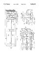
- FIG. 1 is an isometric view showing a layout and angle measurement square made according to the preferred embodiment of the present invention.
- FIG. 2 is a top view of the square of FIG. 1
- FIG. 3 is a side view of the square of FIG. 1
- FIG. 4 is a perspective view of the square of FIG. 1 illustrating the attachment of a standard tape measure as used to mark the top and bottom plates during construction of a wall.
- FIGS. 5A-5B illustrate the use of the square of FIG. 1 for marking metal members.
- FIGS. 6A-6G illustrate a prior art method of locating and marking the center, reference measuring point, and final cut line of a hip or valley rafter top plumb cut using a conventional triangular shaped-square.
- FIGS. 7A-7C illustrate a method of locating and marking the reference measuring point and final cut line of a hip or valley top plumb cut using the square of FIG. 1.
- FIGS. 8A-8C illustrate additional embodiments made according to the invention.
- FIG. 1 shows a perspective view of a layout device and rafter angle measurement square 11 made according to the present invention.
- This square is comprised primarily of an elongated, planar base 12, with two opposing faces.
- the base is rectangularity shaped.
- a planar guide with two opposing faces 13 is integrally connected to one end of base 12.
- the guide extends bi-directional on a plane and is perpendicular and at a right angle to the elongated base 12.
- Rectangular shaped cutouts 14, 15, 16, 17, and 17' are used for marking, viewing, measuring and/or indicia placement.
- the marking indicia may be of any desired type and can be used to make any desired measurements or alignments.
- a level(s) 35 may be attached to the base or guide as shown but is not limited to these locations.
- the length of base 12 is dimensioned longitudinally to cover two or more boards laid side by side (8 inches) (ref. FIG. 4).
- the width of base 12 is dimensioned for the thickness of three boards laid together on edge (4 and 1/2 inches).
- the base encompasses cutouts 15, and 16 with longitudinal edges 21, and 22 parallel to base longitudinal edges 20, and 23.
- the length of edges 21 and 22 are proximate the length of base 12 (6 and 1/2 inches).
- edges 21 and 22 are proximate the thickness of one board (1 and 1/2 inches) and they are positioned so that the distance between longitudinal edges 20 to 21, 21 to 22 and 22 to 23 are substantially equal spaced.
- a transverse edge 24 equal to the width of base 12 is connected at its longitudinal extent opposite guide 13.
- Guide 13 has two opposing edges 33 and 33'.
- Cutout 14 has an edge 14A which is parallel and centered between edges 20 and 21 and extends longitudinally from the intersection of base 12 and guide 13. This cutout is of sufficient length (at least 2 inches) and width (at least 3/16 but not greater than 7/16 inches) to allow viewing and/or marking of a board at edge 14A.
- Cutout 15 has an edge 15A being a distance substantially equal to 0.707 (sine of 45 degrees) times the thickness of a board from edge 20, this distance is 1.06 inches. Therefore, the distance between edges 14A and 15A is substantially 0.207 (0.707-0.5) times a board thickness, this distance is 5/16 inch.
- the relationships of edges 20, 14A, and 15A are constant ratios. These edges, with these ratios, determine the reference measuring point and the final cut line for any given hip or valley type rafter of equal pitched roofs cut at a standard 45 degree angle. This significantly reduces the steps required to mark the desired lines for rafter hip and valley type cuts (as described for FIG. 7).
- Cutouts 17 and 17' extend parallel to and are approximately 3/4 inch from edge 24. These edges are of sufficient width to allow the viewing of the boards edge. These cutouts are used to place indicia to properly locate and/or mark common rafter pitch or angles.
- Notch 18, 18', and 18" are placed extending longitudinally from the junction of base 12 and guide 13 on centers between pairs of edges 20 and 21, 21 and 22, 22 and 23 respectively. These notches provide the user the flexibility to add or subtract one half the thickness of a board relative to any of these parallel edges.
- a beveled edge(s) 25, shown at cutout 14, may be provided to alleviate a potential parallax problem and enhance the reading, measuring and marking when using this square.
- This bevel is not limited as shown but may be added to additional edges to provide the same enhancements.
- Indicia that have a calibrated scales for angles 26, a hip and valley rafter rise to run ratios (pitch) 27 and a common rafter rise to run ratios 28 are provided on or about edges 21, 22, 23, and cutouts 17, and 17'.
- the marking indicia may be of any desired type and can be used to make any desired measurements or alignments.
- a linear indicia 30 with an ascending and descending inch scale is placed on edges 20 and 24 to form a small conventional carpenters-square.
- This carpenters-square arrangement may be used to simplify the marking of a heel cut, measuring two relative distances at right angles or marking a complimentary angle of an existing mark.
- Other uses will become obvious to one skilled in the art of construction.
- a level(s) 35 may be contained in base 12 or guide 13 as shown and, although not shown an additional level(s) may be placed on other angles. This level(s) may be used for the plumbing of walls, determining the pitch of an existing roof and other conventional uses.
- portion 31 of guide 13 extends upwardly a sufficient distance not to exceed the thickness of a board (1 and 1/2 inches).
- Portion 31 should be of adequate thickness (1/8 to 1/4 inch) to firmly hold a conventional tape measure 40 using a tapes belt-clip 41 (ref. FIG. 4).
- Portion 31 contains notches 34 and 34' that are located at one half the thickness of a board (3/4 inch) from base 12 (ref. FIG. 1). This will allow the marking of a center line on the thickness of a board (as shown in FIG. 7B).
- portion 31 could be slotted at it's upper extent to aid in securing tape 40; but is felt that this would limit the flexibility to adjust tape 40 along guide 13 and eliminate the flexibility in selecting any of the multiple, centering notches 18, 8', 18", longitudinal edges 14A, and 20 through 23, measuring locations on base 12.
- Base 12 has the indicia mirrored on an opposing side 36. This provides for left or right handed use of this square.
- FIG. 4 shows how square 11 may be used in marking plates using standard wood components with tape 40 snugly attached to guide 13 upper portion 31 using clip 41.
- a retractable tape 42 is connected to one end of a board 60.
- Base 12 is positioned on board 60 with lip 32 flush against a board thickness 61.
- the user slides square 11 along board 60 a prescribed distance to align tape 42 indicia with centering notch(s) 8, 18', 18"(ref. FIG. 2) or edge 14A.
- the user then accurately marks a board side(s) 62 with a line(s) 43 (up to four parallel) at base 12 using any or all edges 20, 21, 22, and 23 in a single setting.
- edges and centering marks enables the user to place from one to three studs on center settings without subtracting 3/4 inch from every distance measured. Multiple markings are needed for window framing and the like. Rotating the square 180 degrees on side 62 will enable the user to mark from the opposite end of board 60. These advantages greatly reduce the time to perform the same functions using the various conventional tools. Additionally two or more board edges 61 may be marked simultaneously. This is accomplished by setting the boards to be marked on edge 61 and adding an additional board as a spacer on which base 12 is positioned. Then edge(s) 6 are marked basically as explained above.
- FIG. 5A shows how square 11 may be used in marking plates using standard metal component member(s) with tape 40 snugly attached to guide 13 upper portion 31 using clip 41.
- a retractable tape 42 is connected to one end of a member 50.
- Base 12 is positioned on member 50 with lip 32 flush against a member thickness 51.
- the user slides square 11 along member 50 a prescribed distance to align tape 42 indicia with centering notches 18, 8', 8"or edge 14A (ref. FIG. 2).
- the user then accurately marks a member side(s) 52 with a line(s) 53 (up to four parallel) at base 12 using any or all edges 20, 21, 22, and 23, in a single setting; this allows the user to place multiple adjacent studs on center settings, for window framing and the like.
- two or more member thickness' 51 may be marked simultaneously. This is accomplished by setting the members to be marked on member thickness 51 and adding an additional member as a spacer on which base 12 is positioned. Then thickness('s) 51 are marked basically as explained above.
- FIG. 5B shows how square 11 may be used to consecutively mark the adjacent thickness 51 and side 52 of metal material.
- Upper portion 31 of guide 13 is placed flush against thickness 51 and base 12 positioned on side 52 of member 50.
- Two consecutive lines 53' and 53 are then marked on thickness 51 and side 52 at an edge 33' and edge 23 respectively. Rotating the square 180 degrees around member 50 will enable the user to mark all four sides of member 50 in two settings.
- FIG. 6A to 6G is an example of the steps required to find a reference measuring point P and a final top cut mark 68 for a hip or valley top cut when using a conventional triangular shaped-square.
- the triangular shaped-square is pivoted to read a hip/valley rise of 10 and a line 63 is marked on side 62 as in FIG. 6A.
- the triangular shaped-square is flipped and rotated to align a notch 69 with line 63.
- a line 64 is drawn perpendicular to line 63 as shown in FIG. 6B.
- the triangular shaped-square is rotated and a point 65P equal to the thickness of a board is measured and marked on side 62 as shown in FIG. 6C.
- the triangular shaped-square is again flipped and rotated and the guide is placed on thickness 61 and adjusted to find a hip/valley rise of 10 coincident with point 65P.
- a line 65 is marked over point 65P as in FIG. 6D.
- the triangular shaped-square is flipped and with its guide flush against side 62 lines 63' and 65' are drawn across board thickness 61 which lines are perpendicular to line 63 and 65 respectively as shown in FIG. 6E.
- FIG. 6G Next rotation of the triangular shaped-square is required to draw a diagonal joining opposite ends of lines 63' and 65' (ref. FIG. 6E) to form a diagonal line 66 on board thickness 61 as shown in FIG. 6F.
- a line 67 is determined by manipulating the triangular shaped-square and marking on the center of thickness 61 on lines 63' and 65'. Line 67 is drawn connecting these two points. Where line 67 bisects diagonal line 66 is a reference measuring point P.
- a final cut line 68 is determined and marked by measuring one half the length of diagonal 66 and performing the steps shown in FIG. 6C and 6D relative to line 63 using the length just obtained.
- FIG. 7A and 7C illustrate the steps required to find a reference measuring point P' and a final top cut mark 78 for a hip or valley top cut using square 11.
- Guide 13 is set on board 60 at thickness 61 as shown in FIG. 7A and square 11 is pivoted to read a hip/valley rise of 10. Then a reference measuring point line 73 and a final cut line 78 are drawn at edges 14A and 15A respectively on board side 62. Where the line segment 73 intersects thickness 61 and side 62 of board 60 is a reference measuring point P' as shown in FIG. 7C.
- Edge 15A is located a distance of 0.707 times the board thickness (1.06 inches) from edge 20. This allows the user to instantly add or subtract one half the thickness of a board, cut at a 45 degree angle, for any hip or valley rafter angle. Also, it enables the user to mark a final cut line at an extreme end of a board without having to do mathematical calculations.
- edge 14A When marking hip or valley rafters, edge 14A is used to locate reference point P'. Edge 14A also provides the user the flexibility to add or subtract one half a board thickness when marking common rafters. Edge 14A will automatically locate the proper distance for marking a miter cut line at a standard 45 degree miter. This can be accomplished for any given pitch without making calculations and therefore saves time and reduces errors.
- edge 15A which is located 0.207 times a board thickness from edge 14A could be located substantially the same distance from edge 20 or any edge parallel to edge 20.
- FIG. 7B and 7C shows when using square 11 how the following two lines may be drawn.
- a line 77 may be drawn to bisect the board thickness 61 by placing a marker 79 in notch 34 on edge 33 then sliding guide 30 along board thickness 61.
- a line 73' is drawn perpendicular to line 73 also using edge 33.
- FIG. 8A illustrates another preferred embodiment of the present invention.
- square 11 shown as a square 80 is very similar to previously described square 11, with the following alterations noted.
- Cutout 16 (ref. FIG. 2) in square 11 is replaced by an elongated rectangular shaped cutout 19A.
- Cutout 19A is placed so that edges 21' and 22' of base 12' have the same dimensioning as edges 21 and 22 of base 12.
- Cutout 15 and edge 15A of square 11 is a cutout 15' and an edges 15A' in square 80.
- Edges 15A' and 14A' have the same relationships to edge 20' of square 80 as edges 15A and 14A have to edge 20 of square 11.
- a level(s) 35' may be positioned as shown.
- Square 11 and square 80 each have distinct advantages.
- Square 11 with its additional edges provides locations for additional indicia.
- Square 80 can mark an entire side of a board at edge 14A'. This may be used to add or subtract one half a board thickness and automatically locate the proper distance to mark a miter cut line for a standard 45 degree miter. Additionally cutout 19A provides an ergonomic means of griping square 80. Therefore, the preferred embodiment of square 11 or square 80 may be produced.
- FIG. 8B illustrates a triangular shaped-square 88 made to the invention.
- Square 88 retains some general characteristics of square 11 for the following like numbers; a guide 13", edges 14A", 15A", 20", 21" and indicia 26", 27", and 28" (ref. FIG. 2) and therefore only the major differences are discussed.
- This square 88 is a right-triangular member with forty-five degree opposing angles forming a hypotenuse edge 84.
- One edge 20" of the right angle is elongated longitudinally and the other edge of the right angle is used as guide 13".
- Indicia 30" is only on edge 20" of base 12" and a level(s) 35" is placed as shown.
- a triangular cutout 19B is placed on the interior of base 12" with edge 21" forming one of its edges.
- This cutout may be any shape and in a different embodiment it may be eliminated.
- An additional cutout 19C is parallel to hypotenuse 84 of base 12" and extends sufficiently in length and width for the viewing and marking at an edge 82 or an edge 83.
- FIG. 8C illustrates another embodiment made to the present invention.
- square 11 shown as a square 81 is similar to previously described square 11, with the following alterations.
- Edge 23 of square 11 has been deleted on square 81.
- Square 81 and guide 13 are dimensioned two board thickness'wide (3 inches).
- Edges 20 , 21 and 22 of base 12 have the same dimensioning as edges 20, 21 and 22 of base 12.
- Cutout 15 and edge 15A of square 11 is a cutout 15 and an edge 15A in square 81.
- Edges 15A and 14A have the same relationships to edge 20 of square 81 as edges 15A and 14A have to edge 20 of square 11.
- Indicia 27 and 28 are moved to new edges on square 81.
- a level(s) 35 may be positioned as shown.
- Square 81 is basically functional but the user is required to add or subtract 3/4 of an inch when doing plate layout for studs and the like. This is because the tape housing of a twenty five foot or larger conventional tape measure is at least 3 inches long. This is the same width as square 8. This embodiment will provide for the marking of two consecutive studs in one setting.
- inventions of the current invention may be made of any material which may be easily molded, shaped, formed or stamped.
- An advantage of this invention is to provide a method of attaching a conventional tape measure to the square as an accessory. This allows a framer to simultaneously measure and precisely mark a stud(s) on center. Therefore, reducing the steps and time required to perform the same task using separate tools.
- Another advantage of the invention is a square that enables a framer to easily locate the accurate sites for correctly installing studs along top and bottom plates and the like, by identifying and marking on both plates with multiple parallel lines for one or more studs. This reduces the commonly made errors of placing the studs on the wrong side of the marks.
- Another advantage may be the integration of a small carpenter-square at two adjoining edges that form a right angle by using linear indicia along these edges. This provides a standard ruler, facilitates the measuring and marking of distances at right angles such as a seat cut for rafters. Additional uses will become apparent to those skilled in construction.
- Still another advantage is to provide indicia having direct reading scales for common rafters, and hip and valley rafters, for normally used roof configurations of rise to run ratios and to provide indicia as a means to directly determine and measure angles.
- a further advantage is to substantially reduce the amount of steps required in determining the reference measuring point and proper location of a common or hip and valley final cut(s). Thereby reducing the mechanical calculations required to find these locations and thus reduce errors. Also, to provide the ability to easily add or subtract one half the material thickness when marking for these cuts.
- An additional advantage is the ability to properly mark the distance for cutting an outward extending 45 degree miter in a single setting. This can be accomplished for all rafter run to rise ratios without having to calculate or look the distance up in a table, therefore reducing the chance of errors. Also, to provide the ability to add or subtract one half the material thickness for common cuts and the like.
- Another advantage is to provide a square that provides left or right handed use for the marking of materials.
- a further advantage of this square is to provide a square that is easy to understand, learn and operate.
- An additional advantage of this square may be to achieve leveling to determine level and plumb, and to determine pitch or angles of an existing structure using a single tool.
- a final advantage is the easy and economical manufacturing of this square. This is achieved through using commercially available components and materials, modified only to the extent necessary to fit the requirements of the invention.
- edges 20, 14A, and 15A are constant ratios. These edges, with their constant ratios, could be applied or duplicated in relation to any edge(s) parallel to edge 20. Also, edges 14A and 15A could be combined in a single cutout as two opposing edges. In addition cutout 14 could be widened so that the edge opposite to edge 14A is substantially the ratio of 0.207 times the material thickness from edge 20. These edges could be applicable to any square, of any desired shape, and could be adapted to such a square according to the teaching of the present invention.
- the linear indicia on edges 20 and 24 may be of any desired type for making measurements.
- Cutouts 17 and 17' may be placed as required to perform their basic functions or additional cutouts may be added. Also, this square could be made with a magnetically impregnated material or have magnetic plugs inserted. This would hold it place on ferrous material.
Landscapes
- Engineering & Computer Science (AREA)
- Mechanical Engineering (AREA)
- Physics & Mathematics (AREA)
- General Physics & Mathematics (AREA)
- Length-Measuring Instruments Using Mechanical Means (AREA)
- Conveying And Assembling Of Building Elements In Situ (AREA)
Priority Applications (3)
| Application Number | Priority Date | Filing Date | Title |
|---|---|---|---|
| US08/163,881 US5456015A (en) | 1993-12-08 | 1993-12-08 | Construction framing square |
| CA002178333A CA2178333C (fr) | 1993-12-08 | 1994-12-08 | Equerre de trace utilisee en construction |
| PCT/US1994/014175 WO1995015860A1 (fr) | 1993-12-08 | 1994-12-08 | Equerre de trace utilisee en construction |
Applications Claiming Priority (1)
| Application Number | Priority Date | Filing Date | Title |
|---|---|---|---|
| US08/163,881 US5456015A (en) | 1993-12-08 | 1993-12-08 | Construction framing square |
Publications (1)
| Publication Number | Publication Date |
|---|---|
| US5456015A true US5456015A (en) | 1995-10-10 |
Family
ID=22591987
Family Applications (1)
| Application Number | Title | Priority Date | Filing Date |
|---|---|---|---|
| US08/163,881 Expired - Lifetime US5456015A (en) | 1993-12-08 | 1993-12-08 | Construction framing square |
Country Status (3)
| Country | Link |
|---|---|
| US (1) | US5456015A (fr) |
| CA (1) | CA2178333C (fr) |
| WO (1) | WO1995015860A1 (fr) |
Cited By (43)
| Publication number | Priority date | Publication date | Assignee | Title |
|---|---|---|---|---|
| US5727325A (en) * | 1996-05-07 | 1998-03-17 | Mussell; Barry D. | Multipurpose square |
| US5768795A (en) * | 1996-02-20 | 1998-06-23 | Jimenez; Leonard K. | Stud template |
| US5848481A (en) * | 1997-03-24 | 1998-12-15 | Parsons; Don | Combination square and tape measure for use with a tool belt |
| US5884904A (en) * | 1997-12-05 | 1999-03-23 | Martini; Donald | Corner jig and method of using |
| US5937613A (en) * | 1997-04-11 | 1999-08-17 | Vess, Sr.; Michael Gene | Upright stud positioning slide |
| US5992034A (en) * | 1998-01-13 | 1999-11-30 | Prucha; Mark | Attachment for the enhanced measurement accuracy of a combination square |
| US6122834A (en) * | 1997-12-05 | 2000-09-26 | Rester; Glenn Steven | Combination framing and speed square |
| US6260283B1 (en) | 1998-01-16 | 2001-07-17 | Ezee Enterprise, Inc. | Multi-functional carpentry tool |
| US6272758B1 (en) * | 1999-07-26 | 2001-08-14 | Gene R. Wheeler | Steel worker's layout tool |
| US6308699B1 (en) * | 1999-11-03 | 2001-10-30 | Mark R. Schmitt | Paving brick template |
| US6330751B1 (en) * | 1997-12-02 | 2001-12-18 | Larry D. Seaman | Dock leveler apparatus |
| US6484411B1 (en) * | 1999-11-15 | 2002-11-26 | Russell Nixon | Siding layout tool |
| US6578274B1 (en) | 2000-02-25 | 2003-06-17 | Ronald M. Tango, Jr. | Construction layout block |
| US6688014B1 (en) * | 1998-06-26 | 2004-02-10 | Swanson Tool Co., Inc. | Builder's measuring and marking tool |
| US6775916B2 (en) | 2001-05-17 | 2004-08-17 | David C. Sparkes | Framer's layout square |
| US6796046B1 (en) * | 2003-03-21 | 2004-09-28 | William Jeffrey May | Miter cut, plumb cut, and seat cut angle finding system |
| US6868616B2 (en) | 2003-03-07 | 2005-03-22 | James S. Allemand | Builder's measuring and marking tool |
| US20050060902A1 (en) * | 2003-08-11 | 2005-03-24 | Jones Steven K. | Saddle square for marking stud locations |
| USD503603S1 (en) * | 2002-01-29 | 2005-04-05 | Robert R. Pederson | Wallpaper border applicator |
| US20050200913A1 (en) * | 2004-03-11 | 2005-09-15 | International Business Machines Corporation | Systems and methods for identifying complex text in a presentation data stream |
| USD511698S1 (en) | 2004-03-05 | 2005-11-22 | Swanson Tool Co. Inc. | Builder's measuring and marking tool |
| US20060032065A1 (en) * | 2004-03-29 | 2006-02-16 | Howell Stephen E | Kwik leads |
| US20060277776A1 (en) * | 2004-12-15 | 2006-12-14 | Paul Lawrence J | Multipurpose construction gauge |
| US20060277779A1 (en) * | 2004-11-12 | 2006-12-14 | Alan Bauer | Mounting template |
| US20070017107A1 (en) * | 2004-03-29 | 2007-01-25 | Howell Stephen E | Kwik Leads |
| US20080006976A1 (en) * | 2006-07-04 | 2008-01-10 | Tobiah George Heber Riley | Multiple spacing portable framing jig |
| US20090013546A1 (en) * | 2004-12-15 | 2009-01-15 | Slk Development Group, Llc | Hand-held level and plumb tool |
| US20100095527A1 (en) * | 2008-10-17 | 2010-04-22 | Ccm, Inc. | Steel beam and method of manufacture and use |
| US20100154234A1 (en) * | 2008-12-19 | 2010-06-24 | Jarzynka Jr Clifford J | Sliding square for tape measure |
| US20110108428A1 (en) * | 2009-11-06 | 2011-05-12 | Empire Level Mfg. Corp. | Method for Manufacturing High-Visibility Measurement Tool |
| US8146260B1 (en) | 2011-09-07 | 2012-04-03 | Visser Fredric J | Framing square |
| USD657701S1 (en) | 2010-11-05 | 2012-04-17 | Milwaukee Electric Tool Corporation | Square |
| US20120247062A1 (en) * | 2011-04-03 | 2012-10-04 | Henry John Elsasser | Device For Measuring and Cutting Roofing Shingles |
| USD682123S1 (en) * | 2011-06-20 | 2013-05-14 | Neil Robinson | Decking template |
| CN103287171A (zh) * | 2012-03-01 | 2013-09-11 | 约翰逊水平测量及工具制造有限公司 | 具有划线引导凹口的三角板 |
| US20130263462A1 (en) * | 2012-04-10 | 2013-10-10 | William E. Funk | Mechancial spacing apparatus |
| US9151585B2 (en) | 2011-10-06 | 2015-10-06 | John Scott Sanchez | Cabinet installation tool and system of use thereof |
| US9435130B2 (en) | 2015-01-09 | 2016-09-06 | Jb Builders Llc | Layout tool |
| US20170009472A1 (en) * | 2015-07-09 | 2017-01-12 | Lambert Ray Myers | Method and apparatus for positioning, spacing and securement of studs within top and bottom framing plates |
| US20230088802A1 (en) * | 2021-09-17 | 2023-03-23 | International Wood Products, LLC | Template and spacing tool for deck construction and methods of use |
| USD1075530S1 (en) * | 2021-09-17 | 2025-05-20 | International Wood Products, LLC | Template for deck construction |
| US12366076B1 (en) * | 2021-07-12 | 2025-07-22 | Ervin Innovations, LLC | Alignment tool for trim |
| USD1100686S1 (en) | 2022-07-06 | 2025-11-04 | Ervin Innovations, LLC | Alignment tool |
Families Citing this family (3)
| Publication number | Priority date | Publication date | Assignee | Title |
|---|---|---|---|---|
| GB2293457A (en) * | 1994-09-20 | 1996-03-27 | John Mary Patrick Broderick | Device for setting out and measuring angles |
| GB2384744B (en) * | 2002-02-01 | 2003-12-31 | Steve Banks | Timber frame joist grid |
| CN105091684A (zh) * | 2015-09-12 | 2015-11-25 | 杨夕志 | 一种电线槽裁切划线尺 |
Citations (23)
| Publication number | Priority date | Publication date | Assignee | Title |
|---|---|---|---|---|
| US855987A (en) * | 1906-08-08 | 1907-06-04 | Andrew Benedict Schlageter | Combination-square. |
| US1139229A (en) * | 1914-08-05 | 1915-05-11 | Ralph Waldo Requa | Square. |
| CH84466A (de) * | 1919-07-03 | 1920-03-16 | Mueller Ernst Kg | Winkel |
| US2470035A (en) * | 1946-01-10 | 1949-05-10 | Hudkins Clyde | Square |
| US2965969A (en) * | 1955-12-13 | 1960-12-27 | Joseph P Haley | Rafter cut marking guide |
| US3183596A (en) * | 1964-04-23 | 1965-05-18 | Earnest B Shaw | Template |
| US3823481A (en) * | 1972-09-25 | 1974-07-16 | Chapin J | Framing layout jig |
| US4227314A (en) * | 1979-02-22 | 1980-10-14 | Edward Schliep | Carpenter square with tape holder |
| US4361964A (en) * | 1981-03-03 | 1982-12-07 | Hennessee John W | Lay out square |
| US4503624A (en) * | 1983-04-14 | 1985-03-12 | Carl Whiteford | Combination square, scribing tool and plumb level |
| US4574492A (en) * | 1983-02-15 | 1986-03-11 | Tony Miller | Combination layout tool and square |
| US4654978A (en) * | 1985-10-04 | 1987-04-07 | Wolford Jr Otis | Marking guide for use with metal studs |
| US4712307A (en) * | 1987-03-27 | 1987-12-15 | Kish Karl E | Rafter angle measuring device |
| US4742619A (en) * | 1986-09-25 | 1988-05-10 | Swanson Ronald C | Marking tool with wear rims |
| US4944096A (en) * | 1989-09-11 | 1990-07-31 | Tolley Sherman D | Wall stud centering square |
| US4967482A (en) * | 1990-05-02 | 1990-11-06 | Future Line Incorporated | Support bracket applicable to measuring tools |
| JPH0398777A (ja) * | 1989-09-08 | 1991-04-24 | Nippon Telegr & Teleph Corp <Ntt> | 導波管支持金物用マーキングプレート |
| US5077910A (en) * | 1990-11-26 | 1992-01-07 | Smith Peter T | Carpenter's measuring square |
| US5090129A (en) * | 1990-12-10 | 1992-02-25 | Cunningham Philip J | Carpenter square |
| US5113596A (en) * | 1991-06-11 | 1992-05-19 | Meyers Jack G | T-square accessory for tape measure |
| US5170568A (en) * | 1990-01-02 | 1992-12-15 | Wright Robert A | Roofing speed square and method of use |
| US5239762A (en) * | 1992-09-15 | 1993-08-31 | Grizzell James M | Layout tool |
| US5253426A (en) * | 1992-04-23 | 1993-10-19 | Mosbrucker Gregory A | Multi-purpose square |
Family Cites Families (5)
| Publication number | Priority date | Publication date | Assignee | Title |
|---|---|---|---|---|
| US1135259A (en) * | 1914-03-21 | 1915-04-13 | Elmer W Cokely | Try-square. |
| US2571569A (en) * | 1948-11-29 | 1951-10-16 | Richard Edward Allen | Combined square and tape measure |
| US3390461A (en) * | 1966-05-27 | 1968-07-02 | Irvin F. Anderson | Guides |
| AU624061B3 (en) * | 1991-07-18 | 1992-04-01 | Franklin Targarona | Line marking tool |
| US5390426A (en) * | 1993-06-04 | 1995-02-21 | Hull; Anthony K. | Tape measure clip |
-
1993
- 1993-12-08 US US08/163,881 patent/US5456015A/en not_active Expired - Lifetime
-
1994
- 1994-12-08 WO PCT/US1994/014175 patent/WO1995015860A1/fr not_active Ceased
- 1994-12-08 CA CA002178333A patent/CA2178333C/fr not_active Expired - Fee Related
Patent Citations (23)
| Publication number | Priority date | Publication date | Assignee | Title |
|---|---|---|---|---|
| US855987A (en) * | 1906-08-08 | 1907-06-04 | Andrew Benedict Schlageter | Combination-square. |
| US1139229A (en) * | 1914-08-05 | 1915-05-11 | Ralph Waldo Requa | Square. |
| CH84466A (de) * | 1919-07-03 | 1920-03-16 | Mueller Ernst Kg | Winkel |
| US2470035A (en) * | 1946-01-10 | 1949-05-10 | Hudkins Clyde | Square |
| US2965969A (en) * | 1955-12-13 | 1960-12-27 | Joseph P Haley | Rafter cut marking guide |
| US3183596A (en) * | 1964-04-23 | 1965-05-18 | Earnest B Shaw | Template |
| US3823481A (en) * | 1972-09-25 | 1974-07-16 | Chapin J | Framing layout jig |
| US4227314A (en) * | 1979-02-22 | 1980-10-14 | Edward Schliep | Carpenter square with tape holder |
| US4361964A (en) * | 1981-03-03 | 1982-12-07 | Hennessee John W | Lay out square |
| US4574492A (en) * | 1983-02-15 | 1986-03-11 | Tony Miller | Combination layout tool and square |
| US4503624A (en) * | 1983-04-14 | 1985-03-12 | Carl Whiteford | Combination square, scribing tool and plumb level |
| US4654978A (en) * | 1985-10-04 | 1987-04-07 | Wolford Jr Otis | Marking guide for use with metal studs |
| US4742619A (en) * | 1986-09-25 | 1988-05-10 | Swanson Ronald C | Marking tool with wear rims |
| US4712307A (en) * | 1987-03-27 | 1987-12-15 | Kish Karl E | Rafter angle measuring device |
| JPH0398777A (ja) * | 1989-09-08 | 1991-04-24 | Nippon Telegr & Teleph Corp <Ntt> | 導波管支持金物用マーキングプレート |
| US4944096A (en) * | 1989-09-11 | 1990-07-31 | Tolley Sherman D | Wall stud centering square |
| US5170568A (en) * | 1990-01-02 | 1992-12-15 | Wright Robert A | Roofing speed square and method of use |
| US4967482A (en) * | 1990-05-02 | 1990-11-06 | Future Line Incorporated | Support bracket applicable to measuring tools |
| US5077910A (en) * | 1990-11-26 | 1992-01-07 | Smith Peter T | Carpenter's measuring square |
| US5090129A (en) * | 1990-12-10 | 1992-02-25 | Cunningham Philip J | Carpenter square |
| US5113596A (en) * | 1991-06-11 | 1992-05-19 | Meyers Jack G | T-square accessory for tape measure |
| US5253426A (en) * | 1992-04-23 | 1993-10-19 | Mosbrucker Gregory A | Multi-purpose square |
| US5239762A (en) * | 1992-09-15 | 1993-08-31 | Grizzell James M | Layout tool |
Cited By (52)
| Publication number | Priority date | Publication date | Assignee | Title |
|---|---|---|---|---|
| US5768795A (en) * | 1996-02-20 | 1998-06-23 | Jimenez; Leonard K. | Stud template |
| US5727325A (en) * | 1996-05-07 | 1998-03-17 | Mussell; Barry D. | Multipurpose square |
| US5848481A (en) * | 1997-03-24 | 1998-12-15 | Parsons; Don | Combination square and tape measure for use with a tool belt |
| US5937613A (en) * | 1997-04-11 | 1999-08-17 | Vess, Sr.; Michael Gene | Upright stud positioning slide |
| US6330751B1 (en) * | 1997-12-02 | 2001-12-18 | Larry D. Seaman | Dock leveler apparatus |
| US6122834A (en) * | 1997-12-05 | 2000-09-26 | Rester; Glenn Steven | Combination framing and speed square |
| US5884904A (en) * | 1997-12-05 | 1999-03-23 | Martini; Donald | Corner jig and method of using |
| US5992034A (en) * | 1998-01-13 | 1999-11-30 | Prucha; Mark | Attachment for the enhanced measurement accuracy of a combination square |
| US6260283B1 (en) | 1998-01-16 | 2001-07-17 | Ezee Enterprise, Inc. | Multi-functional carpentry tool |
| US6688014B1 (en) * | 1998-06-26 | 2004-02-10 | Swanson Tool Co., Inc. | Builder's measuring and marking tool |
| US6272758B1 (en) * | 1999-07-26 | 2001-08-14 | Gene R. Wheeler | Steel worker's layout tool |
| US6308699B1 (en) * | 1999-11-03 | 2001-10-30 | Mark R. Schmitt | Paving brick template |
| US6484411B1 (en) * | 1999-11-15 | 2002-11-26 | Russell Nixon | Siding layout tool |
| US6578274B1 (en) | 2000-02-25 | 2003-06-17 | Ronald M. Tango, Jr. | Construction layout block |
| US6775916B2 (en) | 2001-05-17 | 2004-08-17 | David C. Sparkes | Framer's layout square |
| USD503603S1 (en) * | 2002-01-29 | 2005-04-05 | Robert R. Pederson | Wallpaper border applicator |
| US6868616B2 (en) | 2003-03-07 | 2005-03-22 | James S. Allemand | Builder's measuring and marking tool |
| US6796046B1 (en) * | 2003-03-21 | 2004-09-28 | William Jeffrey May | Miter cut, plumb cut, and seat cut angle finding system |
| US20050060902A1 (en) * | 2003-08-11 | 2005-03-24 | Jones Steven K. | Saddle square for marking stud locations |
| USD511698S1 (en) | 2004-03-05 | 2005-11-22 | Swanson Tool Co. Inc. | Builder's measuring and marking tool |
| US20050200913A1 (en) * | 2004-03-11 | 2005-09-15 | International Business Machines Corporation | Systems and methods for identifying complex text in a presentation data stream |
| US20060032065A1 (en) * | 2004-03-29 | 2006-02-16 | Howell Stephen E | Kwik leads |
| US20090106992A1 (en) * | 2004-03-29 | 2009-04-30 | Quick Leads Llc | Kwik leads |
| US20070017107A1 (en) * | 2004-03-29 | 2007-01-25 | Howell Stephen E | Kwik Leads |
| US7461461B2 (en) * | 2004-03-29 | 2008-12-09 | Howell Stephen E | Kwik leads |
| US20060277779A1 (en) * | 2004-11-12 | 2006-12-14 | Alan Bauer | Mounting template |
| US20090013546A1 (en) * | 2004-12-15 | 2009-01-15 | Slk Development Group, Llc | Hand-held level and plumb tool |
| US20060277776A1 (en) * | 2004-12-15 | 2006-12-14 | Paul Lawrence J | Multipurpose construction gauge |
| US7975395B2 (en) | 2004-12-15 | 2011-07-12 | Slk Development Group, Llc | Hand-held level and plumb tool |
| US20080006976A1 (en) * | 2006-07-04 | 2008-01-10 | Tobiah George Heber Riley | Multiple spacing portable framing jig |
| US20100095527A1 (en) * | 2008-10-17 | 2010-04-22 | Ccm, Inc. | Steel beam and method of manufacture and use |
| US8240054B2 (en) * | 2008-10-17 | 2012-08-14 | Ccm, Inc. | Method for manufacturing a support beam that includes providing an alignment tool and two pieces of strip material wherein each piece of strip material is curvilinear and the alignment tool is used to position the strip during a joining operation |
| US20100154234A1 (en) * | 2008-12-19 | 2010-06-24 | Jarzynka Jr Clifford J | Sliding square for tape measure |
| US8256125B2 (en) * | 2008-12-19 | 2012-09-04 | Jarzynka Jr Clifford J | Sliding square for tape measure |
| US20110108428A1 (en) * | 2009-11-06 | 2011-05-12 | Empire Level Mfg. Corp. | Method for Manufacturing High-Visibility Measurement Tool |
| USD657701S1 (en) | 2010-11-05 | 2012-04-17 | Milwaukee Electric Tool Corporation | Square |
| US8453341B2 (en) * | 2011-04-03 | 2013-06-04 | Henry John Elsasser | Device for measuring and cutting roofing shingles |
| US20120247062A1 (en) * | 2011-04-03 | 2012-10-04 | Henry John Elsasser | Device For Measuring and Cutting Roofing Shingles |
| USD682123S1 (en) * | 2011-06-20 | 2013-05-14 | Neil Robinson | Decking template |
| US8146260B1 (en) | 2011-09-07 | 2012-04-03 | Visser Fredric J | Framing square |
| US9151585B2 (en) | 2011-10-06 | 2015-10-06 | John Scott Sanchez | Cabinet installation tool and system of use thereof |
| CN103287171A (zh) * | 2012-03-01 | 2013-09-11 | 约翰逊水平测量及工具制造有限公司 | 具有划线引导凹口的三角板 |
| US20130263462A1 (en) * | 2012-04-10 | 2013-10-10 | William E. Funk | Mechancial spacing apparatus |
| US8881418B2 (en) * | 2012-04-10 | 2014-11-11 | William E. Funk | Mechancial spacing apparatus |
| US9435130B2 (en) | 2015-01-09 | 2016-09-06 | Jb Builders Llc | Layout tool |
| US20170009472A1 (en) * | 2015-07-09 | 2017-01-12 | Lambert Ray Myers | Method and apparatus for positioning, spacing and securement of studs within top and bottom framing plates |
| US12366076B1 (en) * | 2021-07-12 | 2025-07-22 | Ervin Innovations, LLC | Alignment tool for trim |
| US20230088802A1 (en) * | 2021-09-17 | 2023-03-23 | International Wood Products, LLC | Template and spacing tool for deck construction and methods of use |
| US11951645B2 (en) * | 2021-09-17 | 2024-04-09 | International Wood Products, LLC | Template and spacing tool for deck construction and methods of use |
| US12304105B2 (en) | 2021-09-17 | 2025-05-20 | International Wood Products, LLC | Template and spacing tool for deck construction |
| USD1075530S1 (en) * | 2021-09-17 | 2025-05-20 | International Wood Products, LLC | Template for deck construction |
| USD1100686S1 (en) | 2022-07-06 | 2025-11-04 | Ervin Innovations, LLC | Alignment tool |
Also Published As
| Publication number | Publication date |
|---|---|
| CA2178333C (fr) | 1999-06-29 |
| WO1995015860A1 (fr) | 1995-06-15 |
| CA2178333A1 (fr) | 1995-06-15 |
Similar Documents
| Publication | Publication Date | Title |
|---|---|---|
| CA2178333C (fr) | Equerre de trace utilisee en construction | |
| US5117560A (en) | Full circle protractor with detachable adjustable leg assembly for measuring angles | |
| US5090129A (en) | Carpenter square | |
| US7398601B2 (en) | Carpenter's pitch square | |
| US5253426A (en) | Multi-purpose square | |
| US5170568A (en) | Roofing speed square and method of use | |
| US5727325A (en) | Multipurpose square | |
| CA1204930A (fr) | Combinaison d'outil et d'equerre de tracage | |
| CA2138677C (fr) | Appareil de mesure polyvalent | |
| US4527337A (en) | Framing stud template | |
| US6293028B1 (en) | Construction tool and method of use | |
| US5113596A (en) | T-square accessory for tape measure | |
| US3212192A (en) | Measuring instrument | |
| US5077910A (en) | Carpenter's measuring square | |
| EP1601927B1 (fr) | Outil de mesure et de marquage du batisseur | |
| US5083380A (en) | Duct notching template apparatus | |
| US4420891A (en) | Framing and layout square | |
| US5787599A (en) | Tape measuring square and adjustable tool guide | |
| WO2000009346A1 (fr) | Outil polyvalent multifonctions | |
| US4462166A (en) | Device for measuring lengths and conforming angles | |
| US7430810B2 (en) | Laser square protractor kit | |
| GB2170916A (en) | Square for use in laying out rafter cuts | |
| US4598482A (en) | Rafter cutting template and tape | |
| CA2949790A1 (fr) | Rapporteur de reperage d'angle | |
| US2656609A (en) | Carpenter's layout tool |
Legal Events
| Date | Code | Title | Description |
|---|---|---|---|
| AS | Assignment |
Owner name: APPLIED CONCEPTS ENGINEERING, OREGON Free format text: ASSIGNMENT OF ASSIGNORS INTEREST;ASSIGNORS:BUTCHER, RICHARD L.;TEDSEN, MICHAEL P.;REEL/FRAME:006791/0884 Effective date: 19931208 |
|
| STCF | Information on status: patent grant |
Free format text: PATENTED CASE |
|
| REMI | Maintenance fee reminder mailed | ||
| FPAY | Fee payment |
Year of fee payment: 4 |
|
| SULP | Surcharge for late payment | ||
| FPAY | Fee payment |
Year of fee payment: 8 |
|
| FPAY | Fee payment |
Year of fee payment: 12 |