US5462368A - Ball bearing block having self-contained bearings - Google Patents
Ball bearing block having self-contained bearings Download PDFInfo
- Publication number
- US5462368A US5462368A US08/297,485 US29748594A US5462368A US 5462368 A US5462368 A US 5462368A US 29748594 A US29748594 A US 29748594A US 5462368 A US5462368 A US 5462368A
- Authority
- US
- United States
- Prior art keywords
- races
- bearing
- hub
- sheave
- ball bearings
- Prior art date
- Legal status (The legal status is an assumption and is not a legal conclusion. Google has not performed a legal analysis and makes no representation as to the accuracy of the status listed.)
- Expired - Lifetime
Links
- 238000010009 beating Methods 0.000 claims description 6
- 229910000831 Steel Inorganic materials 0.000 claims description 3
- 239000010959 steel Substances 0.000 claims description 3
- 238000006073 displacement reaction Methods 0.000 claims description 2
- 239000000463 material Substances 0.000 description 3
- 239000002184 metal Substances 0.000 description 2
- 238000000034 method Methods 0.000 description 2
- 239000004033 plastic Substances 0.000 description 2
- 230000001133 acceleration Effects 0.000 description 1
- 238000004140 cleaning Methods 0.000 description 1
- 238000007689 inspection Methods 0.000 description 1
- 238000005461 lubrication Methods 0.000 description 1
- 230000014759 maintenance of location Effects 0.000 description 1
- 239000002990 reinforced plastic Substances 0.000 description 1
- 238000005096 rolling process Methods 0.000 description 1
- 229910001220 stainless steel Inorganic materials 0.000 description 1
- 239000010935 stainless steel Substances 0.000 description 1
Images

Classifications
-
- F—MECHANICAL ENGINEERING; LIGHTING; HEATING; WEAPONS; BLASTING
- F16—ENGINEERING ELEMENTS AND UNITS; GENERAL MEASURES FOR PRODUCING AND MAINTAINING EFFECTIVE FUNCTIONING OF MACHINES OR INSTALLATIONS; THERMAL INSULATION IN GENERAL
- F16C—SHAFTS; FLEXIBLE SHAFTS; ELEMENTS OR CRANKSHAFT MECHANISMS; ROTARY BODIES OTHER THAN GEARING ELEMENTS; BEARINGS
- F16C19/00—Bearings with rolling contact, for exclusively rotary movement
- F16C19/02—Bearings with rolling contact, for exclusively rotary movement with bearing balls essentially of the same size in one or more circular rows
- F16C19/14—Bearings with rolling contact, for exclusively rotary movement with bearing balls essentially of the same size in one or more circular rows for both radial and axial load
- F16C19/18—Bearings with rolling contact, for exclusively rotary movement with bearing balls essentially of the same size in one or more circular rows for both radial and axial load with two or more rows of balls
-
- F—MECHANICAL ENGINEERING; LIGHTING; HEATING; WEAPONS; BLASTING
- F16—ENGINEERING ELEMENTS AND UNITS; GENERAL MEASURES FOR PRODUCING AND MAINTAINING EFFECTIVE FUNCTIONING OF MACHINES OR INSTALLATIONS; THERMAL INSULATION IN GENERAL
- F16C—SHAFTS; FLEXIBLE SHAFTS; ELEMENTS OR CRANKSHAFT MECHANISMS; ROTARY BODIES OTHER THAN GEARING ELEMENTS; BEARINGS
- F16C13/00—Rolls, drums, discs, or the like; Bearings or mountings therefor
- F16C13/006—Guiding rollers, wheels or the like, formed by or on the outer element of a single bearing or bearing unit, e.g. two adjacent bearings, whose ratio of length to diameter is generally less than one
-
- F—MECHANICAL ENGINEERING; LIGHTING; HEATING; WEAPONS; BLASTING
- F16—ENGINEERING ELEMENTS AND UNITS; GENERAL MEASURES FOR PRODUCING AND MAINTAINING EFFECTIVE FUNCTIONING OF MACHINES OR INSTALLATIONS; THERMAL INSULATION IN GENERAL
- F16C—SHAFTS; FLEXIBLE SHAFTS; ELEMENTS OR CRANKSHAFT MECHANISMS; ROTARY BODIES OTHER THAN GEARING ELEMENTS; BEARINGS
- F16C43/00—Assembling bearings
- F16C43/04—Assembling rolling-contact bearings
- F16C43/06—Placing rolling bodies in cages or bearings
- F16C43/08—Placing rolling bodies in cages or bearings by deforming the cages or the races
Definitions
- the present invention relates to a bearing block or sheave in which a pair of circular rows of ball bearings are disposed between relatively rotatable inner and outer races.
- Bearing blocks or pulleys are widely used on sailing craft to control and change the direction of lines, to provide a mechanical advantage, or otherwise adjust the rigging.
- the small diameter line is usually connected to a larger diameter line to facilitate hand operation beyond the pulleys.
- the lines are used to control various parts of the sailboat rigging without undue clutter.
- Blocks of this nature have outer sheaves with a diameter down to 16 mm or less.
- the block When dealing with so-called micro blocks, assembly of a number of small parts becomes a problem, but the use of rotary bearings, such as ball bearings is highly desirable, in order to reduce friction around a very small turning radius.
- the block should be light in weight, have high load handling capacity for its size, and utilize bearings to reduce friction.
- the main operating components of the bearing block consists solely of hub having a pair of inner bearing races, an outer rotatable sheave having a pair of outer races, and a plurality of ball bearings snap-fitted between the corresponding pairs of inner and outer races.
- the hub is generally cylindrical having ends, and a pair of circular grooves are formed in the hub closely adjacent the ends.
- the grooves define a pair of inner ball bearing races and also define an outer lip which later serves to retain the balls in the final assembly.
- the outer rotatable sheave is generally ring-shaped and has a pair of ring-shaped recesses or shoulders which are open to interior and the sides. These recesses define a pair of outer bearing races concentric with the inner races, and a pair of thrust bearing races for the sheave, to prevent axial displacement of the sheave.
- a plurality of ball bearings are inserted from the sides, and are snap fitted over the lip on the inner race and into operative position between the inner and outer races.
- the bearings carry the radial and axial or thrust loads. the grooves and corresponding lips prevent the bearings from being displaced axially.
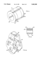
- FIG. 1 is a perspective view of the bearing block of the present invention.
- FIG. 2 is an end view of the block shown in FIG. 1, with the outer sheave shown in cross section.
- FIG. 3 is a sectional view of the outer sheave shown in FIGS. 1 and 2, taken through the axis.
- FIG. 4 is a perspective view of the inner race.
- FIG. 5 is an axial sectional view of the inner race.
- FIG. 6 is a perspective view of a bail or cheek which may be employed to support the block shown in FIG. 1.
- FIGS. 1 and 2 illustrate the bearing block of the present invention.
- the block comprises an outer rotatable sheave 10, which has an outer circumferential U-shaped groove 12 or depression to guide a line which may be reeved thereon.
- the assembly also includes an inner hub 14 and two rows of ball bearings 16 and 18 carried between inner races in the hub and corresponding circular bearing surfaces on the outer sheave 10.
- the central hub 14 is generally cylindrical, in the form of a tube or post, and has a pair of spaced outwardly facing circular grooves 20 and 22 therein, which serve as inner bearing races.
- the grooves 20 and 22 are closely adjacent the annular sides 24 of the hub 14 and define an annular lip 26 between the grooves and the ends.
- the grooves 20 and 22 have a cross sectional radius which is arcuate and slightly larger in radius than the ball bearings used in the assembly.
- the hub 14 is normally considered as the stationary part of the assembly and is either held between side plates attached to a head, for attachment to a support, or the hub itself is fixed to a support.
- the sheave as best shown in FIGS. 2 and 3, is generally ring-shaped, with a central opening 28 and side surfaces 30.
- Annular or ring-shaped recesses or concave open annular shoulders are provided in each side of the sheave, with the recesses being open inwardly onto the sides.
- These recesses define circular or cylindrical concave surfaces 32 and 34, which serve as outer beating races concentric with the inner races, and inner annular surfaces 36 and 38 extending inwardly from the concave walls toward the axis, preferably with a curved radius between the walls.
- the annular surfaces 36 and 38 serve as thrust bearing surfaces.
- the surfaces 32 and 34 may be grooved raceways if desired.
- the groups of ball beatings are made from a metal such as steel, or from a plastic bearing material.
- the diameter of the bearings 16 and 18 is sufficient to rotatably support the outer sheave 10 about an axis of rotation, with the beatings riding in the rounded grooves 22 and 24 and against the outer races 32 and 34 and thrust races 36 and 38 of the sheave.
- the hub and ball bearings are preferably composed of high strength materials such as stainless steel.
- the diameter of the balls is slightly greater than the distance between each annular lip 26 on the inner race and the opposed and overlapping outer races 32 and 34 when the parts are in concentric relationship.
- the ball bearings are inserted into the recesses of the sheave and are snap-fitted over the lips to complete the assembly.
- one or more of the parts may be made from a material which is softer or more flexible than the other parts.
- the sheave 10 may be composed of a reinforced plastic. Plastic beatings may be employed if the hub and sheave are made of metal.
- the outer sheave 10 is disposed around the hub 14 and the parts are displaced radially to provide a large opening at one side, and most of the bearings 16 may be simply poured or dropped into the opening very quickly, with the last few balls being snap-fitted into place. As a result, assembly time is greatly reduced.
- the ball beatings 16 are entirely exposed to the side except around the lips 26, which serve to permanently retain the balls in the assembly. This permits inspection, cleaning and lubrication of the bearings.
- FIG. 6 illustrates a conventional bail or strap to enable mounting or hanging of the sheave assembly.
- the strap comprises a U-shaped strap having an attachment head 50 integral with a pair of side plates 52 and 54 having openings 56 for receiving a pin or rivet (not shown) to secure the inner race 14 between the side plates while the sheave 10 is free to rotate.
- the bearing block of the present invention has several advantages over similar blocks currently in use.
- the inner raceways in the form of circular arcs, prevent point contact with the balls and allow the load to be transferred to the hub along circular arcs. This is very important, especially in very small blocks having small diameter inner races operating at high loads.
- the block of the present invention has an additional advantage in that it is self-contained and may be easily handled.
- the ball bearings also act as thrust bearings and act against an inner surface of the sheave rather than an outer surface. Due to the recesses in the sides of the sheave, the mass of the sheave is reduced, allowing for more rapid acceleration.
- a block with a 16 mm (5/8 inch) diameter sheave on an inner race of about 0.3 inch in diameter has a weight of 8 g or 1/3 oz. and 113 kg or 250 pound free rolling load.
Landscapes
- Engineering & Computer Science (AREA)
- General Engineering & Computer Science (AREA)
- Mechanical Engineering (AREA)
- Rolling Contact Bearings (AREA)
Priority Applications (5)
| Application Number | Priority Date | Filing Date | Title |
|---|---|---|---|
| US08/297,485 US5462368A (en) | 1994-08-29 | 1994-08-29 | Ball bearing block having self-contained bearings |
| AU23377/95A AU701062B2 (en) | 1994-08-29 | 1995-06-30 | Ball bearing block having self-contained bearings |
| CA002153199A CA2153199C (fr) | 1994-08-29 | 1995-07-04 | Palier a roulement a billes monobloc |
| EP95110966A EP0699842B1 (fr) | 1994-08-29 | 1995-07-13 | Poulie à roulement à billes avec des paliers à auto-rétention |
| DE69516773T DE69516773T2 (de) | 1994-08-29 | 1995-07-13 | Kugellagerblock mit selbsthaltenden Lagern |
Applications Claiming Priority (1)
| Application Number | Priority Date | Filing Date | Title |
|---|---|---|---|
| US08/297,485 US5462368A (en) | 1994-08-29 | 1994-08-29 | Ball bearing block having self-contained bearings |
Publications (1)
| Publication Number | Publication Date |
|---|---|
| US5462368A true US5462368A (en) | 1995-10-31 |
Family
ID=23146517
Family Applications (1)
| Application Number | Title | Priority Date | Filing Date |
|---|---|---|---|
| US08/297,485 Expired - Lifetime US5462368A (en) | 1994-08-29 | 1994-08-29 | Ball bearing block having self-contained bearings |
Country Status (5)
| Country | Link |
|---|---|
| US (1) | US5462368A (fr) |
| EP (1) | EP0699842B1 (fr) |
| AU (1) | AU701062B2 (fr) |
| CA (1) | CA2153199C (fr) |
| DE (1) | DE69516773T2 (fr) |
Cited By (10)
| Publication number | Priority date | Publication date | Assignee | Title |
|---|---|---|---|---|
| WO2003060339A1 (fr) * | 2001-12-27 | 2003-07-24 | Yehuda Poran | Mecanisme d'element de retenue de roulement a billes, incorporation et utilisation de ce mecanisme dans un systeme de deplacement articule |
| US20050035338A1 (en) * | 2003-06-19 | 2005-02-17 | Panzarella Thomas A. | Roller assembly for a lifting device for a personal-transportation vehicle |
| US20080067482A1 (en) * | 2006-09-14 | 2008-03-20 | Wireline Technologies, Inc. | Ring sheave |
| US20090087130A1 (en) * | 2006-01-21 | 2009-04-02 | Schaeffler Kg | Runner plate with integrated rolling body raceway |
| WO2009138266A1 (fr) * | 2008-05-14 | 2009-11-19 | Robert Bosch Gmbh | Machine-outil, en particulier machine-outil portative |
| US20110119933A1 (en) * | 2008-05-14 | 2011-05-26 | Robert Bosch Gmbh | Power tool, especially hand-held power tool |
| EP2501638A4 (fr) * | 2009-11-16 | 2013-07-24 | Donald Butler Curchod | Bloc d'élément de roulement avancé |
| USD748740S1 (en) * | 2012-08-14 | 2016-02-02 | Nsk Ltd. | Bearing for yo-yo |
| USD785339S1 (en) * | 2014-10-23 | 2017-05-02 | Griot's Garage, Inc. | Hand applicator buffing pad |
| US20190024719A1 (en) * | 2017-07-19 | 2019-01-24 | Jiaqi Pu | Roller bearing |
Families Citing this family (2)
| Publication number | Priority date | Publication date | Assignee | Title |
|---|---|---|---|---|
| DE19654005A1 (de) * | 1996-12-21 | 1998-06-25 | Schaeffler Waelzlager Ohg | Wälzlagerung für eine Stangenführung |
| DE102006039844A1 (de) * | 2006-08-25 | 2008-03-20 | Ab Skf | Laufrolle |
Citations (8)
| Publication number | Priority date | Publication date | Assignee | Title |
|---|---|---|---|---|
| US472769A (en) * | 1892-04-12 | Pulley | ||
| US678779A (en) * | 1900-09-05 | 1901-07-16 | Frederick Hooker | Ball-bearing. |
| US1210921A (en) * | 1915-07-23 | 1917-01-02 | Garwood Company | Ball-bearing. |
| US2724624A (en) * | 1953-05-29 | 1955-11-22 | Aircraft Armaments Inc | High impact strength bearing |
| US3097898A (en) * | 1960-07-29 | 1963-07-16 | George F Mcmurray | Anti-friction bearing |
| US3360314A (en) * | 1966-02-15 | 1967-12-26 | Loreto Edward G Di | Bearing construction |
| DE2705198A1 (de) * | 1977-02-08 | 1978-08-10 | Albert Ackermann | Kugellager, insbesondere fuer die lagerzapfen einer rolladen-aufwickelwalze |
| US4925322A (en) * | 1988-03-03 | 1990-05-15 | Viv Engineering Inc. | Ball bearing |
Family Cites Families (8)
| Publication number | Priority date | Publication date | Assignee | Title |
|---|---|---|---|---|
| CH467949A (de) * | 1966-11-24 | 1969-01-31 | Staeubli Geb & Co | Kugellager |
| DE1937445A1 (de) * | 1969-07-23 | 1971-02-04 | Automatik Maschb Anton Denk Gm | Auf Kugeln ohne Kaefig laufende Kunststoffrolle |
| DE2224111C3 (de) * | 1972-05-17 | 1975-07-03 | Reich + Co Mellrichstadt, 8744 Mellrichstadt | Laufrolle mit einem zapfenförmigen Lagerteil und einem Doppel-T-förmigen Radkörper aus Kunststoff |
| US3824658A (en) * | 1973-04-19 | 1974-07-23 | Oconomowoc Mfg Corp | Method of fabricating a bearing assembly |
| DE2416282C2 (de) * | 1974-04-03 | 1984-09-27 | Skf Kugellagerfabriken Gmbh, 8720 Schweinfurt | Zweireihiges Wälzlager und Verfahren zum Zusammenbau desselben |
| US4113328A (en) * | 1977-08-22 | 1978-09-12 | C. L. Frost & Son, Inc. | Wheel bearing assembly with plastic bearing seals |
| DE3503215A1 (de) * | 1985-01-31 | 1986-08-07 | Schaeffler Wälzlager GmbH, 6650 Homburg | Schraegkugellager und verfahren zum zusammenbau eines solchen schraegkugellagers |
| DE3822961C2 (de) * | 1988-07-07 | 1996-07-11 | Skf Gmbh | Zweireihiges Wälzlager |
-
1994
- 1994-08-29 US US08/297,485 patent/US5462368A/en not_active Expired - Lifetime
-
1995
- 1995-06-30 AU AU23377/95A patent/AU701062B2/en not_active Ceased
- 1995-07-04 CA CA002153199A patent/CA2153199C/fr not_active Expired - Fee Related
- 1995-07-13 DE DE69516773T patent/DE69516773T2/de not_active Expired - Fee Related
- 1995-07-13 EP EP95110966A patent/EP0699842B1/fr not_active Expired - Lifetime
Patent Citations (8)
| Publication number | Priority date | Publication date | Assignee | Title |
|---|---|---|---|---|
| US472769A (en) * | 1892-04-12 | Pulley | ||
| US678779A (en) * | 1900-09-05 | 1901-07-16 | Frederick Hooker | Ball-bearing. |
| US1210921A (en) * | 1915-07-23 | 1917-01-02 | Garwood Company | Ball-bearing. |
| US2724624A (en) * | 1953-05-29 | 1955-11-22 | Aircraft Armaments Inc | High impact strength bearing |
| US3097898A (en) * | 1960-07-29 | 1963-07-16 | George F Mcmurray | Anti-friction bearing |
| US3360314A (en) * | 1966-02-15 | 1967-12-26 | Loreto Edward G Di | Bearing construction |
| DE2705198A1 (de) * | 1977-02-08 | 1978-08-10 | Albert Ackermann | Kugellager, insbesondere fuer die lagerzapfen einer rolladen-aufwickelwalze |
| US4925322A (en) * | 1988-03-03 | 1990-05-15 | Viv Engineering Inc. | Ball bearing |
Cited By (15)
| Publication number | Priority date | Publication date | Assignee | Title |
|---|---|---|---|---|
| WO2003060339A1 (fr) * | 2001-12-27 | 2003-07-24 | Yehuda Poran | Mecanisme d'element de retenue de roulement a billes, incorporation et utilisation de ce mecanisme dans un systeme de deplacement articule |
| US20050035338A1 (en) * | 2003-06-19 | 2005-02-17 | Panzarella Thomas A. | Roller assembly for a lifting device for a personal-transportation vehicle |
| US7182319B2 (en) * | 2003-06-19 | 2007-02-27 | Cook Technologies, Inc. | Roller assembly for a lifting device for a personal-transportation vehicle |
| US20090087130A1 (en) * | 2006-01-21 | 2009-04-02 | Schaeffler Kg | Runner plate with integrated rolling body raceway |
| US20080067482A1 (en) * | 2006-09-14 | 2008-03-20 | Wireline Technologies, Inc. | Ring sheave |
| US7431269B2 (en) * | 2006-09-14 | 2008-10-07 | Wireline Technologies, Inc. | Ring sheave |
| WO2009138266A1 (fr) * | 2008-05-14 | 2009-11-19 | Robert Bosch Gmbh | Machine-outil, en particulier machine-outil portative |
| US20110119933A1 (en) * | 2008-05-14 | 2011-05-26 | Robert Bosch Gmbh | Power tool, especially hand-held power tool |
| US20110185582A1 (en) * | 2008-05-14 | 2011-08-04 | Robert Bosch Gmbh | Power tool, especially hand-held power tool |
| EP2501638A4 (fr) * | 2009-11-16 | 2013-07-24 | Donald Butler Curchod | Bloc d'élément de roulement avancé |
| USD748740S1 (en) * | 2012-08-14 | 2016-02-02 | Nsk Ltd. | Bearing for yo-yo |
| USD778991S1 (en) | 2012-08-14 | 2017-02-14 | Nsk Ltd. | Bearing for a yo-yo |
| USD785339S1 (en) * | 2014-10-23 | 2017-05-02 | Griot's Garage, Inc. | Hand applicator buffing pad |
| US20190024719A1 (en) * | 2017-07-19 | 2019-01-24 | Jiaqi Pu | Roller bearing |
| US10533609B2 (en) * | 2017-07-19 | 2020-01-14 | Rge Motor Direct Inc. | Roller bearing |
Also Published As
| Publication number | Publication date |
|---|---|
| CA2153199A1 (fr) | 1996-03-01 |
| EP0699842B1 (fr) | 2000-05-10 |
| CA2153199C (fr) | 2005-12-06 |
| DE69516773D1 (de) | 2000-06-15 |
| DE69516773T2 (de) | 2000-12-28 |
| AU701062B2 (en) | 1999-01-21 |
| AU2337795A (en) | 1996-03-14 |
| EP0699842A1 (fr) | 1996-03-06 |
Similar Documents
| Publication | Publication Date | Title |
|---|---|---|
| US5462368A (en) | Ball bearing block having self-contained bearings | |
| US4589856A (en) | Tripot universal joint of the end motion type | |
| EP0175858A1 (fr) | Palier à rouleaux radial | |
| US4472006A (en) | Roller bearing with an improved cage | |
| US4974972A (en) | Crossed roller bearing | |
| GB2152170A (en) | Split ring | |
| GB2057593A (en) | Cylinder roller bearing | |
| US5795258A (en) | Planet washer | |
| US4746232A (en) | Low friction cross roller bearing | |
| US6464397B2 (en) | Ultrathin walled rolling bearing | |
| US6367982B1 (en) | Cylindrical roller bearing | |
| US5567057A (en) | Tilting pad thrust bearing assembly | |
| US5156378A (en) | Bearing block having high strength to weight ratio | |
| US5123756A (en) | Roller bearing and segmented roller retainer therefor | |
| US6267510B1 (en) | Roller bearing | |
| US5489254A (en) | Thrust bearing feature for side plate of bearing block | |
| EP0684408A1 (fr) | Ensemble de palier à rouleaux pour poulie | |
| US5449154A (en) | Bearing assembly for rotary support of a line | |
| JPH0266319A (ja) | 櫛型保持器 | |
| US5125756A (en) | Roller bearing with load-reacted cage | |
| US4588313A (en) | Four-point contact bearing | |
| JPH05280548A (ja) | トリポード構造の等速制御 | |
| US4174138A (en) | Thrust bearing and separator | |
| US11371558B2 (en) | Roller bearing ring and dismounting procedure | |
| US4530610A (en) | Multiple-row roller bearing with a guiding ring |
Legal Events
| Date | Code | Title | Description |
|---|---|---|---|
| AS | Assignment |
Owner name: HARKEN, INC., WISCONSIN Free format text: ASSIGNMENT OF ASSIGNORS INTEREST;ASSIGNOR:LOB, CHARLES J.;REEL/FRAME:007140/0051 Effective date: 19940811 |
|
| STCF | Information on status: patent grant |
Free format text: PATENTED CASE |
|
| FEPP | Fee payment procedure |
Free format text: PAYOR NUMBER ASSIGNED (ORIGINAL EVENT CODE: ASPN); ENTITY STATUS OF PATENT OWNER: SMALL ENTITY |
|
| FPAY | Fee payment |
Year of fee payment: 4 |
|
| FPAY | Fee payment |
Year of fee payment: 8 |
|
| FPAY | Fee payment |
Year of fee payment: 12 |
|
| AS | Assignment |
Owner name: JPMORGAN CHASE BANK, N.A., WISCONSIN Free format text: SECURITY AGREEMENT;ASSIGNOR:HARKEN, INCORPORATED;REEL/FRAME:024640/0395 Effective date: 20100630 |
|
| AS | Assignment |
Owner name: WELLS FARGO BANK, NATIONAL ASSOCIATION, COLORADO Free format text: PATENT SECURITY AGREEMENT;ASSIGNOR:HARKEN INCORPORATED;REEL/FRAME:053789/0291 Effective date: 20200911 |