US5477965A - Packaging element for stacked printed products - Google Patents
Packaging element for stacked printed products Download PDFInfo
- Publication number
- US5477965A US5477965A US08/211,353 US21135394A US5477965A US 5477965 A US5477965 A US 5477965A US 21135394 A US21135394 A US 21135394A US 5477965 A US5477965 A US 5477965A
- Authority
- US
- United States
- Prior art keywords
- packaging element
- localizing
- area
- stack
- packaging
- Prior art date
- Legal status (The legal status is an assumption and is not a legal conclusion. Google has not performed a legal analysis and makes no representation as to the accuracy of the status listed.)
- Expired - Fee Related
Links
- 238000004806 packaging method and process Methods 0.000 title claims abstract description 155
- 239000000463 material Substances 0.000 claims abstract description 30
- 230000003014 reinforcing effect Effects 0.000 claims abstract description 29
- 239000004744 fabric Substances 0.000 claims description 29
- 230000035515 penetration Effects 0.000 claims description 9
- 239000004033 plastic Substances 0.000 claims description 6
- 229920000742 Cotton Polymers 0.000 claims description 4
- 229920001875 Ebonite Polymers 0.000 claims description 4
- 239000002023 wood Substances 0.000 claims description 4
- 229910052751 metal Inorganic materials 0.000 claims description 3
- 239000002184 metal Substances 0.000 claims description 3
- 240000000491 Corchorus aestuans Species 0.000 claims description 2
- 235000011777 Corchorus aestuans Nutrition 0.000 claims description 2
- 235000010862 Corchorus capsularis Nutrition 0.000 claims description 2
- 239000012209 synthetic fiber Substances 0.000 claims description 2
- 229920002994 synthetic fiber Polymers 0.000 claims description 2
- 238000000034 method Methods 0.000 description 13
- 238000013461 design Methods 0.000 description 12
- 239000005022 packaging material Substances 0.000 description 6
- 241000196324 Embryophyta Species 0.000 description 4
- 238000004519 manufacturing process Methods 0.000 description 3
- 239000002985 plastic film Substances 0.000 description 3
- 229920006255 plastic film Polymers 0.000 description 3
- 238000007639 printing Methods 0.000 description 3
- 229910000639 Spring steel Inorganic materials 0.000 description 2
- 229910052782 aluminium Inorganic materials 0.000 description 2
- XAGFODPZIPBFFR-UHFFFAOYSA-N aluminium Chemical compound [Al] XAGFODPZIPBFFR-UHFFFAOYSA-N 0.000 description 2
- 230000001747 exhibiting effect Effects 0.000 description 2
- 238000012858 packaging process Methods 0.000 description 2
- 230000035939 shock Effects 0.000 description 2
- 238000012360 testing method Methods 0.000 description 2
- 239000002699 waste material Substances 0.000 description 2
- 239000002759 woven fabric Substances 0.000 description 2
- 238000005452 bending Methods 0.000 description 1
- 235000013361 beverage Nutrition 0.000 description 1
- 230000015572 biosynthetic process Effects 0.000 description 1
- 239000000969 carrier Substances 0.000 description 1
- 238000010276 construction Methods 0.000 description 1
- 230000007423 decrease Effects 0.000 description 1
- 230000003247 decreasing effect Effects 0.000 description 1
- 238000000151 deposition Methods 0.000 description 1
- 239000000835 fiber Substances 0.000 description 1
- 238000009963 fulling Methods 0.000 description 1
- 230000004807 localization Effects 0.000 description 1
- 238000012986 modification Methods 0.000 description 1
- 230000004048 modification Effects 0.000 description 1
- 238000012536 packaging technology Methods 0.000 description 1
- 238000012856 packing Methods 0.000 description 1
- 239000010893 paper waste Substances 0.000 description 1
- 238000012545 processing Methods 0.000 description 1
- 230000002035 prolonged effect Effects 0.000 description 1
- 239000002994 raw material Substances 0.000 description 1
- 230000002787 reinforcement Effects 0.000 description 1
- 238000009877 rendering Methods 0.000 description 1
- 239000011343 solid material Substances 0.000 description 1
- XLYOFNOQVPJJNP-UHFFFAOYSA-N water Substances O XLYOFNOQVPJJNP-UHFFFAOYSA-N 0.000 description 1
- 238000003466 welding Methods 0.000 description 1
Images


Classifications
-
- B—PERFORMING OPERATIONS; TRANSPORTING
- B65—CONVEYING; PACKING; STORING; HANDLING THIN OR FILAMENTARY MATERIAL
- B65D—CONTAINERS FOR STORAGE OR TRANSPORT OF ARTICLES OR MATERIALS, e.g. BAGS, BARRELS, BOTTLES, BOXES, CANS, CARTONS, CRATES, DRUMS, JARS, TANKS, HOPPERS, FORWARDING CONTAINERS; ACCESSORIES, CLOSURES, OR FITTINGS THEREFOR; PACKAGING ELEMENTS; PACKAGES
- B65D75/00—Packages comprising articles or materials partially or wholly enclosed in strips, sheets, blanks, tubes or webs of flexible sheet material, e.g. in folded wrappers
- B65D75/04—Articles or materials wholly enclosed in single sheets or wrapper blanks
- B65D75/14—Articles or materials wholly enclosed in single sheets or wrapper blanks in sheets or blanks folded-up around all sides of the contents from a portion on which the contents are placed
-
- A—HUMAN NECESSITIES
- A45—HAND OR TRAVELLING ARTICLES
- A45C—PURSES; LUGGAGE; HAND CARRIED BAGS
- A45C7/00—Collapsible or extensible purses, luggage, bags or the like
- A45C7/0059—Flexible luggage; Hand bags
- A45C7/0095—Flexible luggage; Hand bags comprising a plurality of hinged panels to be unfolded in one plane for access purposes
-
- B—PERFORMING OPERATIONS; TRANSPORTING
- B65—CONVEYING; PACKING; STORING; HANDLING THIN OR FILAMENTARY MATERIAL
- B65D—CONTAINERS FOR STORAGE OR TRANSPORT OF ARTICLES OR MATERIALS, e.g. BAGS, BARRELS, BOTTLES, BOXES, CANS, CARTONS, CRATES, DRUMS, JARS, TANKS, HOPPERS, FORWARDING CONTAINERS; ACCESSORIES, CLOSURES, OR FITTINGS THEREFOR; PACKAGING ELEMENTS; PACKAGES
- B65D2313/00—Connecting or fastening means
- B65D2313/02—Connecting or fastening means of hook-and-loop type
Definitions
- the invention relates to a packaging element, especially for packaging and shipping a stack of printed products, like newspapers, magazines, books, prospectuses, catalogs or the like.
- the stacked newspapers or magazines are enveloped in a plastic film.
- the envelopment is done by means of a special packaging machine, which wraps the plastic film around a stack of newspapers or magazines and closes the wrapper, formed in this manner, by welding.
- a packaging band is cemented around the packaging element or a band is wound around said packaging element. For this method of packaging large amounts of film and other packing materials are consumed.
- the filled packaging element is provided with a labelled stick-on with the address of the newspaper dealer or the newspaper messenger and delivered. As soon as the filled packaging element arrives at its place of destination, it is opened by tearing or severing the band material and the plastic wrapper in order to remove the newspapers or magazines. Finally the newspapers are removed and the packaging material is thrown away.
- An unfoldable container for receiving objects in particular a school bag for carrying books, which is made of a light-weight, flexible, relatively tough and relatively solid material, is known from the DE-OS 21 20 668.
- This container exhibits a central field and two pairs of opposing flaps, made of one piece with the central field.
- the inner surfaces of one flap and the outer surfaces of the respective opposing flap are provided with interacting connecting means, which mesh together so as to be detachable, in order to hold together the flaps, when, upon tucking in the one flap is laid on the opposing other flap.
- a foldable cardboard shipping container for objects in particular cans of beverage, is known from the FR-OS 25 97 835, where a belt is wound around the objects to be shipped. This belt absorbs the weight of the objects during shipment, so that the load is taken off of the shipping container.
- the belt is run through slots in the shipping container to the outside and serves as a handle element. While carrying by means of the handle element, not the packaging but rather the objects are braced, whereas the packaging in turn rests on the objects.
- the invention is based on the problem of providing a reusable packaging element, which makes it possible to localize tightly and rigidly a stack of printed products not only by hand but also by machine and also facilitates the manipulation and shipment of the stack of printed products.
- the special blank of the packaging element the connection of the individual sections of the blank for its construction with predominantly detachable fastening means and the choice of packaging material enable a reuseability and a mechanical and manual localization of the printed products and guarantees their optimal protection against damages especially during shipment, as explained in detail in the following.
- the packaging element according to the invention is made of a tear-resistant woven fabric or film material. This material prevents the packaging element from being destroyed during mechanical or manual assembly or disassembly and during shipment due to resulting shock and frictional forces. Furthermore, this material provides for high flexibility of the packaging element. The flexibility reduces the wear of the packaging element during frequent use and is, moreover, important for a simple mechanical or even manual wrapping of the newspapers. In particular, the packaging element can be folded together and even compressed without damage owing to the flexibility of the material. This state allows the packaging element to be collected compactly and returned without any problems to the printing plant.
- the flexibility of the packaging element has also the advantage that during both a mechanical and manual packaging procedure no problems are created if the height of the stack of the wrapped product is, for example, slightly exceeded. In so doing, there is no need to detect the height of the packet.
- the packaging element reacts by means of its closing method independently of the control to a wide range of stack heights of the printed products to be packaged. During the manufacturing process the packaging element can be modified specifically to the user in any arbitrary format in consideration of the possible minima and maxima according to the values gained from experience in packaging technology.
- the blank of the packaging element exhibits an approximately rectangular receiving area for the stack of printed products, at whose four side corners a localizing area is pivot-mounted for localizing the stack of printed products. Owing to this blank the packaging element can be assembled in a simple manner by swinging the localizing areas and then closed after filling with printed products.
- the newspaper buyer who receives a stack of newspapers packaged in this manner, can loosen with effortless ease the packaging element, deposited on the underside of the receiving area, and can swing out the localizing areas, connected according to the invention to predominantly detachable fastening means, until he can remove the printed products from the packaging element. Owing to the affixing of detachable fastening means, the packaging elements cannot be damaged upon opening and removal of the printed products.
- the localizing areas are divided into side faces and top faces, where the top faces in the closed state of the packaging element overlap at least in part. Attached to the top face of the localizing area, which is folded up last when closing, is another side face, which in the filled state of the packaging element, can always be fastened by means of detachable fastening means to the side face of the opposing localizing area.
- the inside of the two localizing areas, to be folded up last, and the receiving area carry a continuous reinforcing band, which is arranged in the middle and which is cemented on and/or woven in. Expediently the reinforcing band in the region of the outer localizing area is woven in such a manner into the side face and top face that it forms handle elements on the outside of the top face of the localizing area that is folded up last.
- the side face, bordering the related top face, and the other side face are stressed only in the longitudinal direction of their face, so that their fastening means cannot detach themselves and consequently cannot lift up the top strap provided with the handle elements.
- the reinforcing band can also move to the outside at the side face of the localizing area that is to be folded up last and form a handle element.
- the handle elements serve the purpose of handling without damage when removing the package from the conveyor belt and during subsequent shipping.
- the packaging element can be readily carried and manipulated at the handle elements, whereby the continuous reinforcing band that is arranged in the middle supports the packaging element at the faces which are at the bottom and the side in the carried position.
- the penetration points of the reinforcing band can be reinforced at the side face and/or the top face.
- round bars which are arranged at the penetration points of the reinforcing band, are arranged parallel to the penetration points and reach under the top face and over the reinforcing band, serve as reinforcement.
- the penetration points do not tear out even with prolonged rough use; and the round bars parallel to the penetration points serve as a tensile load abutment and distribute the load over a larger area of the localizing areas.
- the localizing areas can exhibit a rectangular, trapezoidal, triangular surface shape or a combination of these surface shapes.
- the localizing areas can be designed and arranged symmetrically or asymmetrically relative to the lateral bisecting line of the receiving area.
- the localizing areas can present identical or dissimilar surface shapes.
- Suitable materials for the packaging element are film and woven fabric, natural fiber fabrics such as cotton fabric, mixed cotton fabric, jute fabric, synthetic fiber fabric or a combination of these materials serving as the fabric material.
- the fabric material can be treated so as to be water-repellant; it can be impregnated or coated.
- the localizing areas can be made of an expandable material, preferably a netted fabric or latticed fabric.
- This design is especially expedient, if packaging elements of uniform size are to be used for packaging stacks exhibiting a stack height that varies significantly. As the intrinsic stability of a stack decreases with increasing stack height, the localizing forces of the packaging element increases with increasing expansion, so that a good stability of the filled and sealed packaging element is always obtained.
- a practical design of the invention provides that the packaging element is assembled from two webs of fabric that cross over each other.
- the packaging element can be fabricated from commercially available webs of fabric, working from rolls, without requiring a special blank. At the same time the double layer of the webs of fabric in the region of the receiving area results in a desired increased rigidity and stability.
- Velcro® hook and loop fasteners serve as the detachable fastening means.
- Two Velcro strips are arranged along the lateral edges of the top faces, whereby the top faces to be attached one on top of the other carry the meshing Velcro strips alternatingly on their top side and on their bottom side.
- the opposing arrangement of two Velcro strips or fleece strips is designed in an advantageous manner in such a manner that, when containers are stacked into empty packaging elements, no Velcro strip makes contact with the fleece strip of a packaging element situated above or below.
- the empty packaging element can be removed, for example, to the filling station or the conveyor belt without any problems.
- another Velcro strip is arranged on the top side of the top face of the localizing area to be folded up secondly near the lateral edge exhibiting the fixing area to be folded up last and the bottom side of the top face, which is to be fastened next and belongs to the localizing area to be folded up third.
- This design enables that a localizing area or a subsection of the localizing area can be pivoted as a sachel flap not only for removal of but also for filling with newspapers or magazines, without significantly impairing the stability.
- the packaging element can be used optionally as a newspaper bag for delivering newspapers by the newspaper deliverer or as an opened bag in the bicycle carrier or in the passenger car.
- Another design of the invention provides that counterweights, preferably rounded off flat bars, are incorporated at least on the outermost lateral edge of the top face.
- this design weighs down the top faces at their side ends and, thus, causes secondly a linear guide of the packaging element sides during the mechanical or manual assembly of the packaging element by means of a packaging machine or by hand.
- the counterweights which are made, for example, of spring steel or aluminum, can be inserted into the hollow seam prepared for them.
- the receiving area is made of light-weight metal, plastic, hard rubber, wood or cardboard or reinforced by means of a plate made of these materials.
- the receiving area of the packaging element is reinforced in a simple manner. Even valuable magazines can be shipped protected from bending in the packaging element according to the invention.
- the increased stability is important especially when the packaging element is used as a bag.
- feet are attached to the rear side of the receiving area. They can be placed in such a manner that they rest against the counterweights when the filled packaging elements are stacked.
- the packaging elements can be deposited on the receiving area without getting them dirty. Furthermore, at this stage it is possible to stack the packaged newspapers without the risk of the individually filled packaging elements shifting with respect to one another.
- FIG. 1 is a schematic of a packaging element blank.
- FIG. 2 is a schematic of the packaging element blank from FIG. 1 with additional features.
- FIG. 3 depicts a preferred embodiment of the packaging element blank.
- FIGS. 4-9 are schematics of the individual packaging steps, using the packaging element according to the invention.
- FIG. 10 depicts a packaging element used as a bag.
- FIG. 11 depicts a completely filled and closed packaging element on a conveyor belt
- FIGS. 12-21 depict other possible designs of a packaging element blank.
- FIG. 1 is a schematic of a blank of a packaging element 1, which is made of a tear resistant fabric or film material and exhibits a rectangular receiving area 40 for the newspapers or magazines.
- a rectangular localizing area 13, 15, 21, 23 can be pivoted at each of the four lateral edges of the rectangular receiving area 40.
- Each localizing area 13, 15, 21, 23 comprises a side face 12, 14, 22, 24, which is somewhat higher than the height of the stack of newspapers to be enveloped, and a top face 10, 16, 20, 26, which is attached pivotably thereto, and another side face 26A.
- the receiving area 40 is provided for the purpose of depositing newspapers or magazines; i.e., the size of the area 40 with the side length A and C (see arrow A, C in FIG. 1) corresponds to the contact area of the newspapers or magazines to be filled into said packaging element.
- the result is a simple mechanical filling of the packaging element 1 by stacking the newspapers or magazines on the receiving area 40.
- the top faces 10, 16, 20, 26 are designed just as large as the receiving area 40 (see arrow A, C in FIG. 1).
- the result is an optimal wrapping of the stack of newspapers or magazines.
- the stability of the packaging element 1 is increased, a feature that is also especially important for use of the packaging element 1 as a bag.
- the packaging element 1 is made of a tear-resistant fabric material, which has already been used for a long time for the manufacture of newspaper carriers, which are used almost daily and in all weather often for years and have been quite successful there. Naturally a special plastic film could also be used.
- the fabric prevents the packaging element 1 from being destroyed due to shock and frictional forces during the mechanical assembly and disassembly and during shipment. Furthermore, it provides high flexibility of the packaging element 1. The wear that results automatically from frequent use is reduced by the flexibility of the packaging element 1. Furthermore, the flexibility is important for simple mechanical or manual wrapping of the packaging element 1, as will be explained below. In particular, the packaging element 1 can be folded together and even compressed without damage owing to the flexibility of the fabric material. Thus, the packaging elements can be collected compactly and later brought to the printing plant.
- the blank of the packaging element 1 shown here is formed in the simplest manner by merely crossing the fabric webs 2 and 3.
- the outside of webs 2, 3 is water repellant, so that during shipment of the packaging element 1 no moisture can penetrate the packaging element 1.
- the webs 2 and 3 are sewn, rivetted, cemented or welded together in their overlapping region, which forms the receiving area 40 for the newspapers or magazines to be stacked, so that the individual localizing areas 13, 15, 21, 23 are formed at the four lateral edges of the receiving area 40.
- FIGS. 2 and 3 are schematics of a blank of a packaging element from FIG. 1, where FIG. 2 illustrates the arrangement of the Velcro® hook and loop fastening strips 50-59, whereas FIG. 3 shows the arrangement of a reinforcing strip 61, which is partially woven into the localizing areas.
- the circular points on the receiving area 40 denote the position of the feet, which can rest against the flat bars 41, 42, 43 when two filled packaging elements 1 are stacked.
- stacking packaged newspapers is possible, without the risk of the individually filled packaging elements 1 shifting with respect to one another.
- the packaging element 1 can be deposited on the rear side of the receiving area 40 without getting soiled.
- the receiving area 40 can also be reinforced by means of a plate made of plastic, hard rubber or wood (not illustrated). Thus, the stability of the packaging element 1 is increased.
- the reinforcing plate can be attached to the receiving area 40 with attachment elements, which are designed as feet on the rear side of the receiving area 40.
- attachment elements which are designed as feet on the rear side of the receiving area 40.
- the reinforcing plate can be attached to the fabric or film material in one working step with the affixing of the feet.
- an attachment of the feet to the reinforcing plate is extremely durable.
- Velcro fasteners 50 to 59 are affixed on the side faces 12, 14, 22, 24 and/or top faces 10, 16, 20, 26 of the packaging element 1.
- the Velcro fasteners 50 to 59 enable that the mechanical or also manual overlapping of the localizing areas 13, 15, 21, 23 or the top faces 10, 16, 20, 26 and the other side face 26A and their connection, and the closure of the packaging element as well can be performed in one working phase.
- the Velcro fasteners 51 to 59 are designed as Velcro strips 51 to 59, where two Velcro strips are arranged along the lateral edges of the top faces 10, 16, 20, 22, 26 and the other side face 26A.
- top faces 10, 16, 20, 22, 26, to be arranged one on top of the other, and the other side face 26A carry the meshing Velcro strips 51 to 59 alternatingly on their opposing upper and bottom sides, so that they mesh when the top faces 10, 16, 20, 22, 26 and the other side face 26A are overlapped.
- the result is an optimal fastening together of the top faces 10, 16, 20, 22, 26 and the other side face 26A and easy opening of the packaging element 1.
- Flat bars 41, 42, 43, 44 are incorporated into the outermost lateral edge of the top faces 10, 16, 20, 26.
- the flat bars 41, 42, 43, 44 weigh down the top faces 10, 16, 20 and the other side face 26A in such a manner that the result is a simplification of the mechanical assembly and also a linear closure of the packaging element 1 by means of a packaging machine.
- the flat bars 41, 42, 43, 44 which are made, for example of spring steel or aluminum, can be inserted into the hollow seam.
- the flat bars are 1 to 3 mm thick, so that they cannot be bent during a scheduled mechanical or manual assembly.
- the flat bars 41, 42, 43, 44 are rounded off in order not to destroy the fabric by means of sharp edges.
- the localizing areas 21 and 23 and the receiving area 40 carry a continuous reinforcing band 61, which is affixed in the center.
- the localizing areas 21 and 23 are those that lie on the outside in the closed state.
- the reinforcing band 61 is woven into the side face 24 and the top face 26 in such a manner that said area forms handle elements 62, 63 on the outside of the side face 24 and the top face 26.
- the penetration points 64, 65 of the reinforcing band 61 are reinforced on the side face 24 and on the top face 26. Round bars 66, parallel to the penetration points 64, reach over the reinforcing band 61 and reach under the top faces 26.
- a packaging element 1 whose blank comprises a rectangular receiving area 40 with rectangular localizing areas 13, 15, 21, 23, which can be pivoted at the lateral edges, has been placed with the underside of its rectangular receiving area 40 on a conveyor unit of a packaging device (FIG. 4) and has been subsequently filled with the newspapers or magazines.
- FIGS. 4 and 5 depict the packaging element 1 with the localizing areas 13, 15, 21, 23 and an address label (shipping code/package slip and the like), which is indicated with a dashed line on the illustrated underside of the packaging element, arranged on the top side of the localizing area 23, and marked with the reference numeral 60.
- FIG. 4 and 5 depict the packaging element 1 with the localizing areas 13, 15, 21, 23 and an address label (shipping code/package slip and the like), which is indicated with a dashed line on the illustrated underside of the packaging element, arranged on the top side of the localizing area 23, and marked with the reference numeral 60.
- FIG. 4 and 5 depict the packaging element 1 with the localizing areas 13, 15, 21, 23 and an address label (shipping code/package slip and the like), which is indicated with a dashed line on the illustrated underside of the packaging element, arranged on the top side of the localizing area 23, and marked with the reference numeral 60.
- FIG. 4 and 5 depict the packaging element 1 with the localizing areas 13, 15, 21, 23
- the tool element (not visible in the Figures) corresponding with the localizing area 13 is activated.
- the tool element moves the localizing area 13 in the direction of the arrow over the stack of newspapers.
- the process step shown in FIG. 6 follows, starting from the packaging element 1 with the localizing area 13 which can be swung onto the stack of newspapers.
- the tool element (not visible in the Figure) corresponding with the localizing area 15 is activated and moves the localizing area 15 around the stack of newspapers in the direction of the arrow.
- the localizing areas 13 and 15 are automatically connected together due to the meshing of the Velcro strips, arranged on the underside of the localizing area 15, with the Velcro strips, arranged on the top side of the localizing area 13, when both localizing areas 13 and 15 make contact. Additional process steps can be dispensed with.
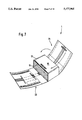
- the next process step is explained with reference to FIG. 7.
- the tool element (not visible), which belongs to the localizing area 21, is activated. Said tool element moves the localizing area 21 around the partially wrapped stack of newspapers in the direction of the arrow, so that the Velcro strip on the underside of the localizing area 21 and the Velcro strip on the top side of the localizing area 15 mesh automatically when the localizing area 21 is lowered, thus connecting together the localizing areas.
- the tool element which corresponds with the localizing area 23 and which moves the localizing area 23 around the stack of newspapers in the direction of the arrow, is activated in a subsequent process step, which is shown in FIG. 8.
- the Velcro strips on the top side of the localizing area 21 and on the underside of the localizing area 23 mesh together and close the packaging element 1.
- each localizing area 13, 15, 21, 23 can be pivoted around the stack of newspapers.
- the pivoting procedure enables a simple packaging process, in which the complicated movements of the tool elements are dispensed with.
- FIG. 9 shows the filled and closed packaging element.
- the address label 60 is arranged visibly on the top side of the packaging element 1.
- the packaging element can be deposited on its side face 22 for the purpose of removing the newspapers and can be opened by swinging out the localizing area, provided for this purpose, simultaneously unfastening the Velcro fastener; and thus said packaging element can be used as a newspaper bag.
- Handle elements 62, 63, arranged on the packaging element 1, can further raise the manipulability of such a newspaper bag.
- FIG. 11 depicts a totally filled and closed packaging element on a conveyor belt.
- FIGS. 12 to 21 depict other possible embodiments of a packaging element blank. Shown are the receiving area 40; the localizing areas 13, 15, 21 and 23 and the side faces 12, 14, 22, 24, subdividing the localizing areas 13, 15, 21, and 23; top faces 10, 16, 20, 26; and the other side face 26A.
- the boundary between the top faces 10, 16, 20, 26, on the one hand, and the side faces 12, 14, 22, 24 and the other side face 26A, on the other hand, are not absolutely specified, but rather can vary somewhat as a function of the height of the stack.
- the localizing areas of the packaging element shown in FIG. 1 border totally the lateral edges of the receiving area 40 and their rectangular shape extends as far as the respective outer edge
- the localizing areas in the drawing according to FIG. 12 are formed through the combination of two rectangles of varying width.
- the rectangular subareas adjoining the receiving area 40 extend completely over the lateral edges of the receiving area 40; and the other rectangular subareas are reduced to the width of narrow belts.
- all of the localizing areas 13, 15, 21, 23 are designed as narrow belts and border only a section of the lateral edge of the receiving area 40. It is also possible to dimension the localizing areas 13 and 15, on the one hand, and the localizing areas 21 and 23, on the other hand, with varying widths.
- FIG. 14 depicts an embodiment, where the localizing areas 13, 15, 21 and 23 present a combined trapezoidal and rectangular shape. At the same time the trapezoidal subarea totally borders the lateral edges of the receiving area 40; and rectangular narrow subareas adjoin the narrower edges of the trapezoidal subareas.
- the localizing areas are formed through the combination of trapezoidal subareas with rectangular subareas and through the combination of different trapezoidal subareas.
- a trapezoidal subarea borders the receiving area 40, whereby, however, the trapezoidal subarea extends only partially along the lateral edge of the receiving area 40. Rectangular narrow subareas adjoin the narrower edges of the trapezoidal subareas.
- the localizing area 23 comprises a first trapezoidal subarea, which totally borders said receiving area along the lateral edge of the receiving area 40 and a second trapezoidal subarea, which borders the narrower edge of the first trapezoidal subarea.
- the localizing area 21 envelops a rectangular subarea, which completely borders said receiving area 40 along the lateral edge of the receiving area 40, and a trapezoidal subarea bordering the rectangular subarea.
- FIG. 16 shows an embodiment, where the localizing areas 13, 15, 21 and 23 present a combined rectangular and triangular shape. At the same time rectangular subareas totally border said receiving area along the lateral edge of the receiving area 40; and triangular subareas adjoin the rectangular subareas.
- all of the localizing areas 13, 15, 21, and 23 exhibit triangular shapes with identical legs.
- the localizing areas 13, 15 and 23 extend totally along the lateral edge of the receiving area 40, yet the localizing area 21 only partially.
- the localizing areas 13, 15, 21 and 23 of the embodiment shown in FIG. 18 also exhibit a triangular shape, but not a triangular shape with identical legs. Rather the triangles are arranged nonsymmetrically relative to the lateral bisecting line of the respective lateral edge of the receiving area 40 and extend only over a subregion of the respective lateral edge.
- the embodiment according to FIG. 19 comprises two localizing areas 13 and 15 shaped like a triangle with equal legs and two other localizing areas 21 and 23 with two opposing straight edges and two opposing concave edges. Whereas the localizing areas 15 and 21 extend totally along the lateral edge of the receiving area 40, the localizing areas 13 and 23 extend only over a subregion of the respective lateral edge.
- the embodiment shown in FIG. 20 comprises two localizing areas 21 and 23 with two opposing straight edges and two opposing concave edges.
- the outer one of the straight edges is shorter than the other, so that the localizing areas 21 and 23 taper toward the outside.
- Two other localizing areas 13 and 15 form a crescent shape and comprise a straight edge, extending in part along the lateral edge of the receiving area 40, and a concave and a convex edge, which form a tip on the outside.
- FIG. 21 depicts another packaging element, which comprises three rectangular localizing areas 13, 15, 21 and a trapezoidal localizing area 23.
- the localizing areas 15, 21 and 23 extend totally along the lateral edge of the receiving area 40, the localizing area 13 only in part. All of the localizing areas 13, 15, 21 and 23 are made of a netted fabric, which can expand in order to adapt to the different stack heights.
- a plastic window can be integrated into the top faces in a packaging element made of a fabric material, so that the content of the package can be recognized without any additional sticker and without opening the packaging element.
- the sequence of individual steps of the packaging process can be modified.
Landscapes
- Engineering & Computer Science (AREA)
- Mechanical Engineering (AREA)
- Packaging Of Special Articles (AREA)
- Basic Packing Technique (AREA)
- Packages (AREA)
- Wrappers (AREA)
Applications Claiming Priority (3)
| Application Number | Priority Date | Filing Date | Title |
|---|---|---|---|
| DE4227290.4 | 1992-08-18 | ||
| DE4227290A DE4227290C1 (de) | 1992-08-18 | 1992-08-18 | Verpackungshülle, insbesondere zur Verpackung und zum Transport von einem Stapel Zeitungen oder Zeitschriften |
| PCT/DE1993/000745 WO1994004416A1 (fr) | 1992-08-18 | 1993-08-17 | Element d'emballage, notamment pour emballer et transporter une pile d'imprimes, tels que journaux, revues, livres, prospectus, catalogues ou produits similaires |
Publications (1)
| Publication Number | Publication Date |
|---|---|
| US5477965A true US5477965A (en) | 1995-12-26 |
Family
ID=6465789
Family Applications (1)
| Application Number | Title | Priority Date | Filing Date |
|---|---|---|---|
| US08/211,353 Expired - Fee Related US5477965A (en) | 1992-08-18 | 1993-08-17 | Packaging element for stacked printed products |
Country Status (7)
| Country | Link |
|---|---|
| US (1) | US5477965A (fr) |
| EP (1) | EP0607416B1 (fr) |
| JP (1) | JPH07504388A (fr) |
| AT (1) | ATE123732T1 (fr) |
| DE (2) | DE4227290C1 (fr) |
| DK (1) | DK0607416T3 (fr) |
| WO (1) | WO1994004416A1 (fr) |
Cited By (17)
| Publication number | Priority date | Publication date | Assignee | Title |
|---|---|---|---|---|
| US5930956A (en) * | 1995-11-02 | 1999-08-03 | Stephen Trosper | Dropcloth |
| US20040247374A1 (en) * | 2003-06-06 | 2004-12-09 | Smith Christopher M. | Binding wrapper |
| US20070183839A1 (en) * | 2005-11-16 | 2007-08-09 | Walker Thomas S | Bound component with adjustable elastic device |
| US7377692B1 (en) * | 2004-02-18 | 2008-05-27 | Hugo Troncoso | Thermal insulative device and method |
| US20080169338A1 (en) * | 2005-03-14 | 2008-07-17 | Yihe Han | Versatile Packaging Box For Products |
| US20090101256A1 (en) * | 2006-06-07 | 2009-04-23 | Jlm Accessories Ltd. | Barbeque cover assembly |
| US20090321205A1 (en) * | 2006-11-09 | 2009-12-31 | Mynorse As | Fabric for packing |
| US20110005647A1 (en) * | 2009-07-10 | 2011-01-13 | Koozee Armor Products, Llc | Adjustable, portable, flexible equipment wrap |
| US20140023295A1 (en) * | 2012-07-19 | 2014-01-23 | Benjamin Wagner | Transforming insulated container and multipurpose mat |
| US20140193100A1 (en) * | 2011-08-24 | 2014-07-10 | Ferag Ag | Filling system for introducing flat articles into a container |
| DE102016122106A1 (de) * | 2016-11-17 | 2018-05-17 | Florian Heil | Vorrichtung zum Schutz eines Bauteils und Verwendung derselben |
| US20180326686A1 (en) * | 2017-05-11 | 2018-11-15 | Pregis Innovative Packaging Llc | Stock material units for a dunnage conversion machine |
| US10619907B2 (en) * | 2017-05-31 | 2020-04-14 | Keith A. Kenneally | Refrigerated, thermally insulated, collapsible cover system, assembly and method of using to transport perishable products |
| USD903761S1 (en) * | 2017-04-13 | 2020-12-01 | Christine Hill | Organizer |
| US11020930B2 (en) | 2017-05-11 | 2021-06-01 | Pregis Innovative Packaging Llc | Splice member on stock material units for a dunnage conversion machine |
| US11247826B2 (en) * | 2013-02-20 | 2022-02-15 | Packaging One Limited | Wrap around container |
| EP4488190A1 (fr) * | 2023-07-06 | 2025-01-08 | Corplex Slovakia s.r.o. | Emballage recyclable réutilisable et méthode de son pliage |
Families Citing this family (4)
| Publication number | Priority date | Publication date | Assignee | Title |
|---|---|---|---|---|
| DE4415605C2 (de) * | 1994-05-04 | 1998-08-27 | Thomas Herbeck | Vorrichtung zum Verschließen eines flexiblen Verpackungselementes zur Verpackung von stapelbarem, insbesondere blattförmigem Gut |
| DE19541140A1 (de) * | 1995-10-27 | 1997-04-30 | Siemens Ag | Tragetasche für einen quaderförmigen Gegenstand |
| DE19711157C2 (de) * | 1996-08-14 | 1998-07-09 | Uwe Koslowski | Tasche zur Aufnahme von mobilen Telekommunikationsgeräten |
| DE102020000792A1 (de) | 2020-02-06 | 2021-08-12 | Daniela Kissinger | Nachhaltige Verpackung mit vereinfachter Möglichkeit des Verpackens von Gegenständen. |
Citations (14)
| Publication number | Priority date | Publication date | Assignee | Title |
|---|---|---|---|---|
| DE209785C (fr) * | ||||
| US202720A (en) * | 1878-04-23 | Improvement in mailing-packages | ||
| US550870A (en) * | 1895-12-03 | cooke | ||
| GB158359A (en) * | 1919-11-04 | 1921-02-04 | Alfred Dunhill | A new or improved wrapper for packages, parcels and the like |
| US2071232A (en) * | 1935-09-03 | 1937-02-16 | Lulu W Langehennig | Wrapper for books and other merchandise |
| US3623526A (en) * | 1969-09-23 | 1971-11-30 | Flowood Ind Ltd | Knockdown folding package |
| DE2120668A1 (de) * | 1970-07-28 | 1972-02-17 | Flowood Industries Ltd , Dartmouth, Nova Scotia (Kanada) | Behalter |
| DE2510871A1 (de) * | 1974-03-15 | 1975-10-16 | Jaroslav Dipl Ing Hajek | Verpackungsvorrichtung zur herstellung eines altpapierpaketes |
| US4620396A (en) * | 1985-05-02 | 1986-11-04 | Bjorntwedt Kris E | Protective cover of flexible sheet material |
| US4627223A (en) * | 1982-02-05 | 1986-12-09 | Janhonen Veikko Ilmari | Package blank and packaging method |
| FR2597835A1 (fr) * | 1986-04-23 | 1987-10-30 | Icp Sa | Emballage ferme a lien peripherique interieur non tendu maintenu dans un plan parallele au fond |
| GB2221841A (en) * | 1988-08-20 | 1990-02-21 | G R O Pentith | Water-impermeable wrapping material |
| US4958759A (en) * | 1989-05-17 | 1990-09-25 | Irene Jarvis | Combined book cover book carrier |
| US5248034A (en) * | 1991-05-02 | 1993-09-28 | Pussikeskus Oy | Book package blank and method and machine for its fabrication |
Family Cites Families (7)
| Publication number | Priority date | Publication date | Assignee | Title |
|---|---|---|---|---|
| FR2515971A1 (fr) * | 1981-11-06 | 1983-05-13 | Kermadec Remi De | Mallette de jeux polyvalente |
| DD209785A5 (de) * | 1982-05-05 | 1984-05-23 | Janhonen Veikko Ilmari | Verfahren zur herstellung einer verpackung und hierzu dienendes verpackungselement |
| US4562952A (en) * | 1984-09-28 | 1986-01-07 | Carole Chinman | Wrapper for clothing |
| DE8503676U1 (de) * | 1985-02-11 | 1985-05-02 | William Prym-Werke GmbH & Co KG, 5190 Stolberg | Bodengleiter an Gepäckbehältnissen, wie Koffern, Taschen, od. dgl. |
| US4750609A (en) * | 1986-12-01 | 1988-06-14 | Gia Felis | Combination mailing carton and portfolio |
| DE8802480U1 (de) * | 1988-02-25 | 1988-07-21 | Mosburger AG, Wien | Versandhülle |
| DE4101595A1 (de) * | 1991-01-21 | 1992-07-23 | Lothar Wittig | Verfahren zum warnen von fahrzeuglenkern vor schulkindern |
-
1992
- 1992-08-18 DE DE4227290A patent/DE4227290C1/de not_active Expired - Fee Related
-
1993
- 1993-08-17 JP JP6505772A patent/JPH07504388A/ja active Pending
- 1993-08-17 EP EP93918888A patent/EP0607416B1/fr not_active Expired - Lifetime
- 1993-08-17 US US08/211,353 patent/US5477965A/en not_active Expired - Fee Related
- 1993-08-17 WO PCT/DE1993/000745 patent/WO1994004416A1/fr not_active Ceased
- 1993-08-17 DK DK93918888.4T patent/DK0607416T3/da active
- 1993-08-17 DE DE59300264T patent/DE59300264D1/de not_active Expired - Fee Related
- 1993-08-17 AT AT93918888T patent/ATE123732T1/de not_active IP Right Cessation
Patent Citations (16)
| Publication number | Priority date | Publication date | Assignee | Title |
|---|---|---|---|---|
| DE209785C (fr) * | ||||
| US202720A (en) * | 1878-04-23 | Improvement in mailing-packages | ||
| US550870A (en) * | 1895-12-03 | cooke | ||
| GB158359A (en) * | 1919-11-04 | 1921-02-04 | Alfred Dunhill | A new or improved wrapper for packages, parcels and the like |
| US2071232A (en) * | 1935-09-03 | 1937-02-16 | Lulu W Langehennig | Wrapper for books and other merchandise |
| US3623526A (en) * | 1969-09-23 | 1971-11-30 | Flowood Ind Ltd | Knockdown folding package |
| DE2120668A1 (de) * | 1970-07-28 | 1972-02-17 | Flowood Industries Ltd , Dartmouth, Nova Scotia (Kanada) | Behalter |
| US3683987A (en) * | 1970-07-28 | 1972-08-15 | Flowood Ind Ltd | Knock-down folding package |
| DE2510871A1 (de) * | 1974-03-15 | 1975-10-16 | Jaroslav Dipl Ing Hajek | Verpackungsvorrichtung zur herstellung eines altpapierpaketes |
| CH572839A5 (fr) * | 1974-03-15 | 1976-02-27 | Hajek Jaroslav | |
| US4627223A (en) * | 1982-02-05 | 1986-12-09 | Janhonen Veikko Ilmari | Package blank and packaging method |
| US4620396A (en) * | 1985-05-02 | 1986-11-04 | Bjorntwedt Kris E | Protective cover of flexible sheet material |
| FR2597835A1 (fr) * | 1986-04-23 | 1987-10-30 | Icp Sa | Emballage ferme a lien peripherique interieur non tendu maintenu dans un plan parallele au fond |
| GB2221841A (en) * | 1988-08-20 | 1990-02-21 | G R O Pentith | Water-impermeable wrapping material |
| US4958759A (en) * | 1989-05-17 | 1990-09-25 | Irene Jarvis | Combined book cover book carrier |
| US5248034A (en) * | 1991-05-02 | 1993-09-28 | Pussikeskus Oy | Book package blank and method and machine for its fabrication |
Cited By (24)
| Publication number | Priority date | Publication date | Assignee | Title |
|---|---|---|---|---|
| US5930956A (en) * | 1995-11-02 | 1999-08-03 | Stephen Trosper | Dropcloth |
| US20040247374A1 (en) * | 2003-06-06 | 2004-12-09 | Smith Christopher M. | Binding wrapper |
| US7165788B2 (en) * | 2003-06-06 | 2007-01-23 | Smith Christopher M | Binding wrapper |
| US20070085328A1 (en) * | 2003-06-06 | 2007-04-19 | Smith Christopher M | Binding wrapper |
| US7377692B1 (en) * | 2004-02-18 | 2008-05-27 | Hugo Troncoso | Thermal insulative device and method |
| US20080169338A1 (en) * | 2005-03-14 | 2008-07-17 | Yihe Han | Versatile Packaging Box For Products |
| US7819249B2 (en) * | 2005-03-14 | 2010-10-26 | Yihe Han | Versatile packaging box for products |
| US20070183839A1 (en) * | 2005-11-16 | 2007-08-09 | Walker Thomas S | Bound component with adjustable elastic device |
| US20090101256A1 (en) * | 2006-06-07 | 2009-04-23 | Jlm Accessories Ltd. | Barbeque cover assembly |
| US20090321205A1 (en) * | 2006-11-09 | 2009-12-31 | Mynorse As | Fabric for packing |
| US20110005647A1 (en) * | 2009-07-10 | 2011-01-13 | Koozee Armor Products, Llc | Adjustable, portable, flexible equipment wrap |
| US20140193100A1 (en) * | 2011-08-24 | 2014-07-10 | Ferag Ag | Filling system for introducing flat articles into a container |
| US20140023295A1 (en) * | 2012-07-19 | 2014-01-23 | Benjamin Wagner | Transforming insulated container and multipurpose mat |
| US11247826B2 (en) * | 2013-02-20 | 2022-02-15 | Packaging One Limited | Wrap around container |
| DE102016122106A1 (de) * | 2016-11-17 | 2018-05-17 | Florian Heil | Vorrichtung zum Schutz eines Bauteils und Verwendung derselben |
| USD903761S1 (en) * | 2017-04-13 | 2020-12-01 | Christine Hill | Organizer |
| US20180326686A1 (en) * | 2017-05-11 | 2018-11-15 | Pregis Innovative Packaging Llc | Stock material units for a dunnage conversion machine |
| CN110612201A (zh) * | 2017-05-11 | 2019-12-24 | 普里吉斯创新包装有限责任公司 | 用于垫料转换机的库存材料单元上的条带组件 |
| US10940659B2 (en) * | 2017-05-11 | 2021-03-09 | Pregis Innovative Packaging Llc | Strap assembly on stock material units for a dunnage conversion machine |
| US11020930B2 (en) | 2017-05-11 | 2021-06-01 | Pregis Innovative Packaging Llc | Splice member on stock material units for a dunnage conversion machine |
| US11571872B2 (en) | 2017-05-11 | 2023-02-07 | Pregis Innovative Packaging Llc | Splice member on stock material units for a dunnage conversion machine |
| US11890830B2 (en) | 2017-05-11 | 2024-02-06 | Pregis Innovative Packaging Llc | Strap assembly on stock material units for a dunnage conversion machine |
| US10619907B2 (en) * | 2017-05-31 | 2020-04-14 | Keith A. Kenneally | Refrigerated, thermally insulated, collapsible cover system, assembly and method of using to transport perishable products |
| EP4488190A1 (fr) * | 2023-07-06 | 2025-01-08 | Corplex Slovakia s.r.o. | Emballage recyclable réutilisable et méthode de son pliage |
Also Published As
| Publication number | Publication date |
|---|---|
| WO1994004416A1 (fr) | 1994-03-03 |
| EP0607416B1 (fr) | 1995-06-14 |
| JPH07504388A (ja) | 1995-05-18 |
| EP0607416A1 (fr) | 1994-07-27 |
| DK0607416T3 (da) | 1995-11-13 |
| DE59300264D1 (de) | 1995-07-20 |
| DE4227290C1 (de) | 1994-01-13 |
| ATE123732T1 (de) | 1995-06-15 |
Similar Documents
| Publication | Publication Date | Title |
|---|---|---|
| US5477965A (en) | Packaging element for stacked printed products | |
| US4479243A (en) | Collapsible receptacle with prefabricated lift loops and method of making | |
| US4143796A (en) | Collapsible receptacle for flowable materials | |
| US4224970A (en) | Collapsible receptacle for flowable materials | |
| US4457456A (en) | Collapsible receptacle with static electric charge elimination | |
| FI109587B (fi) | Ympäristön kanssa sopusoinnussa olevasta materiaalista koostuva ja kok oonpuristettuja joustavia artikkeleita sisältävä pakkaus | |
| US5050742A (en) | Easy opening package containing compressed flexible articles | |
| US4759473A (en) | Collapsible receptacle with integral sling | |
| CA1308390C (fr) | Sac a cargo et methode de fabrication connexe | |
| US3285407A (en) | Protective containers and mounting means therefor | |
| AU773762B2 (en) | Dispensing box provided with an integral handle | |
| EP0504317A1 (fr) | Systeme d'emballage souple a ouverture laterale, possedant une poignee pour le transport orientee longitudinalement et fixee aux cotes lateraux. | |
| JPH09501892A (ja) | パッケージ及び前記パッケージの製造方法 | |
| CA2441075A1 (fr) | Sac refermable pourvu d'un soufflet extensible | |
| WO2010151367A1 (fr) | Conteneurs de marchandises en vrac flexibles pouvant être soulevés par le dessous par un chariot élévateur à fourche et système de support | |
| EP1670701B1 (fr) | Gaine | |
| US3301452A (en) | Handle | |
| GB2050298A (en) | Collapsible receptacle with integral sling | |
| AU2009220000A1 (en) | Pouch for picking up and carrying waste such as canine excrement | |
| SK12572000A3 (sk) | Taška na nesenie ovocia a zeleniny | |
| EP1877327B1 (fr) | Bande fibreuse adaptee au transport de materiau en feuille | |
| EP0180379A2 (fr) | Conteneurs intermédiaires pour matériaux en vrac | |
| GB1581437A (en) | Containers | |
| GB2081213A (en) | Flexible bulk container | |
| EP2447183A1 (fr) | Procédé de fabrication d'emballage groupé |
Legal Events
| Date | Code | Title | Description |
|---|---|---|---|
| FEPP | Fee payment procedure |
Free format text: PAYOR NUMBER ASSIGNED (ORIGINAL EVENT CODE: ASPN); ENTITY STATUS OF PATENT OWNER: SMALL ENTITY |
|
| REMI | Maintenance fee reminder mailed | ||
| LAPS | Lapse for failure to pay maintenance fees | ||
| FP | Lapsed due to failure to pay maintenance fee |
Effective date: 19991226 |
|
| STCH | Information on status: patent discontinuation |
Free format text: PATENT EXPIRED DUE TO NONPAYMENT OF MAINTENANCE FEES UNDER 37 CFR 1.362 |