US5482225A - Process for loading a processing machine having a fine centering step and apparatus for this purpose - Google Patents
Process for loading a processing machine having a fine centering step and apparatus for this purpose Download PDFInfo
- Publication number
- US5482225A US5482225A US08/198,534 US19853494A US5482225A US 5482225 A US5482225 A US 5482225A US 19853494 A US19853494 A US 19853494A US 5482225 A US5482225 A US 5482225A
- Authority
- US
- United States
- Prior art keywords
- band
- coil
- turntable
- centering
- unwinding
- Prior art date
- Legal status (The legal status is an assumption and is not a legal conclusion. Google has not performed a legal analysis and makes no representation as to the accuracy of the status listed.)
- Expired - Fee Related
Links
Images




Classifications
-
- B—PERFORMING OPERATIONS; TRANSPORTING
- B21—MECHANICAL METAL-WORKING WITHOUT ESSENTIALLY REMOVING MATERIAL; PUNCHING METAL
- B21D—WORKING OR PROCESSING OF SHEET METAL OR METAL TUBES, RODS OR PROFILES WITHOUT ESSENTIALLY REMOVING MATERIAL; PUNCHING METAL
- B21D43/00—Feeding, positioning or storing devices combined with, or arranged in, or specially adapted for use in connection with, apparatus for working or processing sheet metal, metal tubes or metal profiles; Associations therewith of cutting devices
- B21D43/02—Advancing work in relation to the stroke of the die or tool
- B21D43/021—Control or correction devices in association with moving strips
- B21D43/023—Centering devices, e.g. edge guiding
Definitions
- the invention relates to a process and apparatus for loading a processing machine with a band-like material and for finely centering the material.
- the invention starts, in a first step, from the knowledge that at least some of the phenomena described above may be due to the centering, and this gives rise to the object which is to provide an improved centering process, to make the plant cheaper and to permit a shorter length. This is achieved in a surprisingly simple manner by the features disclosed herein.
- Reliable operation of a band-clamping means on a coil in an unwinding station can be achieved by an apparatus as disclosed herein.
- FIG. 1 shows a plant according to the invention for loading with a straightening machine
- FIG. 2 shows a punch press having a loading apparatus according to the invention and without a straightening machine
- FIG. 3 shows an enlarged view of a detail from FIG. 1 to illustrate a lifting platform, which is shown in
- FIG. 4 in plan view in two different planes along the line IV--IV of FIG. 3;
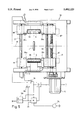
- FIG. 5 shows a centering means according to the invention
- FIG. 6 shows a tool carrier for receiving the band centering unit according to the invention, and, if required, take-off rolls and possibly also shears, all in modular design, in a horizontal section, for which FIG. 6A is an enlarged view of an actuating means for a band clamp taken along line 6A-6A showing the band clamp in a band clamping position, and FIG. 6B is an enlarged view of an actuating means for a band clamp similar to FIG. 6A showing the band clamp in a band releasing position;
- FIG. 7 and 8 each show an oblique view of a variant of the lifting means for the coils.
- FIG. 9 shows an axonometric view of a preferred embodiment of the unwinding station.
- the band-like material 4 is fed to a straightening machine 22.
- This band-like material 4 is unwound from a coil 2 on an unwinding station 1 at the right-hand side of FIG. 1.
- the band-like material 4 which, as can be seen, lies in a vertical plane from coil 2 onward since the coil is unwound with its axis of rotation 5 vertical, passes through a band transport and turning means 20, which in principle may be similar to that of FIG. 9 of EP-A-0 267 357.
- the band-like material 4 is aligned on centering rollers 6 beforehand with the middle of intake rolls 21, which--in the direction of movement of the band 4--are downstream of a pair of take-off rolls 9 which may take off directly from coil 2.
- the take-off rolls 9 (because of the vertical plane of the band at this point) possess vertically oriented axes, whereas the axes of the intake rolls 21, after rotation through 90° by the band transport and turning means 20 connected to the take-off mechanism, are horizontal.
- These centering rollers are analogous to those in FIG. 5 but of course arranged rotated through 90°.
- the band-like material 4 can then, if necessary, pass through a straightening machine 22 which has rollers 50, 51 which straighten the band, and a loop zone (not shown) before the entrance to a processing machine 18, for example a welding machine, in this case a high-frequency punch press (which is distinguished by the arrangement of balancing masses for rapid punching movement and is housed in soundproof housing 19), which loop zone can be replaced by the combined loop and turning zone 24 when the straightening machine 22 is omitted.
- a processing machine 18 for example a welding machine, in this case a high-frequency punch press (which is distinguished by the arrangement of balancing masses for rapid punching movement and is housed in soundproof housing 19), which loop zone can be replaced by the combined loop and turning zone 24 when the straightening machine 22 is omitted.
- a processing machine 18 for example a welding machine, in this case a high-frequency punch press (which is distinguished by the arrangement of balancing masses for rapid punching movement and is housed in soundproof housing 19), which loop zone
- the coil 2 is arranged on a lifting stage 3 having a supporting platform.
- the lifting stage 3 it is also possible to provide another form of vertically displaceable carriage.
- An edge sensor 26, expediently for the upper edge of the coil 2 is provided for correct centering at the height of the take-off rolls 9, especially in this case. This does not of course take into account the width of the band-like material on the coil 2, so that this step is virtually only a coarse centering, as is sufficient for pallet winches and has been proposed in DE-B-1,296,475, for example with an optoelectrical converter.
- the lifting stage is designed for a load of this magnitude and its drive is controlled by the sensor 26.
- the lifting stage 3 carries the turntable 7, via which the particular coil 2 can be driven in the unwinding and, if required, also the winding direction.
- the lifting means and unwinding drive form an unwinding station 1 which, in its upper section, can be designed as a magazine for further coils 15.
- the unwinding station has at least two, preferably three or four, supports 12 which have catches 12a at regular intervals, for example in two vertical rows side by side, as encountered in furniture construction.
- Retaining elements 12b which support the horizontal cassettes 87 (FIG. 3; also see EP-A-0267357) or underlays 72 (FIG. 1, 3) of the coils 15 (FIG. 1), can be suspended in these locking orifices.
- FIG. 1 when applied to the storage of coils this has the advantage that, in the case of coils which are broader than the spacing of the catches 12a, there is no need to change the spacing of the retaining elements 12b because--as is evident from the higher coils 15 (with broader band material) in FIG.
- supports 12 having a distribution of catches 12a can also be used for converting or expanding an unwinding station. If in fact it is desired to replace a conventional unwinding station, as shown in the stated EP-A-0 267 357, by one having a lifting means, the latter could also be suspended directly in the support 12 without requiring a separate frame.
- the lifting means may be of different designs, for example may also have fluid cylinder units. What is important, however, is that it can be lifted to more than two positions.
- the lifting means operates with elongated traction means, such as cables or (preferably) chains 73 and can thus be fastened with the aid of an anchoring bar 74 to the catches 12a or, according to FIG. 3, preferably to the blocks 13 firmly connected to the supports 12 or their connecting walls (not shown).
- elongated traction means such as cables or (preferably) chains 73
- At least one drive motor 8 or 76 is arranged on the lifting stage 3 itself.
- the motor 8 is intended for driving the turntable 7 while a drive shaft of the lifting means can be driven by the motor 76 via a gear 77 (FIG. 3), so that there is no need for any further installations for mounting such a lifting means.
- the gear 77 is expediently self-locking, for example in the form of a worm gear.
- An output cable of the edge sensor 26--as known per se for lift controls-- may be in the form of a mechanical sensor with a roll at the end of a lever in order to operate a switch is connected to the motor 76 and its lift control which is not shown and is similar to an elevator control.
- guide rollers 80 are arranged on the lifting stage 3, in the peripheral region of the turntable 7 (only two thereof are shown in FIG. 4).
- sliding guides 81 are connected to the lifting means, since it is then merely necessary to push in the lifting stages 3 carrying the essential elements.
- sliding guides 81 it is clear that they have as little friction as possible--simply in view of the high weight resting on them.
- Roller guides, as used in drawer guides, are possible, but it is simpler and more stable if they are provided with a low-friction lining, in particular of plastic.
- chains 73 it is advantageous to arrange them in the manner of a block and tackle, for which purpose two chain wheels 83 are fastened to a drive shaft 82 (FIG. 3, 7), which chain wheels cooperate with deflection wheels 84 on an axle parallel to the shaft 82. Furthermore, according to FIG. 3, further deflection wheels 85, 86 are arranged above these.
- a drive adapter which consists virtually only of a support 72 for a set of rolls 88 shown in FIG. 3 and 4, of which FIG. 3 shows the right one in section and the left one in side view.
- Each of these rolls adapts to the particular speed of the turntable 87 and transmits it without friction to the coil underlay (not shown) which is located above and carries coil 2 or 15, without there being any need for the inclined conical surfaces requiring a special embodiment of the turntable in the case of conical gear wheels.
- a gear box 89, above which is arranged a center bearing 90 with driver pins 71 for the turntable 7 is also coordinated with the rotary drive motor 8. Since, as stated, the band-like material 4 is taken off from the coil in principle with the aid of the take-off rolls 9, the rotary drive 8 for the coil is not absolutely essential; instead, the band 4 can simply be taken off from the rolls 9, similarly to the capstan drive of a tape recorder. However, a preferable procedure is that described in the simultaneously submitted application Ser. No. 07/775,806 (filed Oct. 11, 1991), "Process for controlling the loading of a processing machine with band-like material and apparatus for this purpose" of the same applicant, which is herewith considered disclosed.
- the band 4 taken off in a vertical plane from the coil 2 is centered prior to being turned into the horizontal position, as shown in FIG. 5.
- a frame 92 is provided, on which two guide columns 93 are expediently fastened in the vertical position.
- the apparatus shown in FIG. 5 is virtually a measuring means which readjusts the height adjustment of the lifting stage 3 so that the band-like material 4 is unwound at a central level M and in this position.
- centering surfaces opposite one another preferably in the form of centering rolls 6, can be moved toward one another with the aid of the drive 16 until they come into contact with an edge of the band 4 and transmit a corresponding signal to the lifting motor 76, which thus lifts the lifting stage 3 to the height corresponding to the centered position until the other centering surface also rests against the opposite edge of the band.
- the drive for the centering roll 6 may be of any form, for example also fluidic. However, it is preferable to use a worm 97 which is driven by a motor 16 and has, roughly as far as the central plane M, a left-handed thread on the one side and a right-handed thread on the other. In this way, it is possible to ensure, without complicated synchronization means, that both rolls 6 can move toward one another by the same amount and at the same speed.
- Two mobile supports 98 which have, at their right end (based on FIG. 5), a corresponding internal thread 97' engaging the worm 97 and are guided in their movement by the guide columns 93, cooperate with the two thread sections of the worm 97.
- Each of these carriages 98 carries an axle 95 on which the centering roller 6 is rotatably mounted and hence a longitudinal movement of the band 4, as soon as it rests against the roller, is not hindered.
- the worm 97 plays the role of a synchronizing means for the movement of the two carriages 98, and it is thus clear that they can be replaced by any other synchronizing means, for example if a separate cylinder drive or motor is coordinated with each carriage 98.
- a sensor which travels together with the carriage 98 and in this case is formed--together with a reflector--as light barrier 28a is connected to each of the centering rollers 6. If, therefore, the particular carriage 98 travels to the edge of a band 4 to be centered, the light barrier is interrupted at the moment when the roller 6 reaches the associated band edge. The time when the band edge is reached could certainly also be determined by measuring any consequent increase in the current at the motor 16, but this might lead to undesired stresses in the band 4, and the arrangement shown is therefore more advantageous.
- a logical element 94 with an AND informs the control stage 91 of the motor 76 and a control stage 96 for the motor 16 that the centering process has ended, and causes both motors to be switched off.
- a loop zone which is preferably in the form of a combined loop and turning zone 24--as shown in FIG. 2-- with the loop guides 25.
- These have an infeed roller cage 48 and an outlet roller cage 48'.
- the loop zone also has the loop sensor 28, already described with reference to FIG. 2, for the size of the loop.
- the free mobility in height of this band section for the centering process is ensured, without loss of space or particular measures, by virtue of the fact that the loop zone 24 in which the band 4 rests loosely is downstream of the centering means.
- lift drives in this case expediently in the form of fluidic cylinder units, such as pneumatic cylinders 35, are provided for at least one of the loop guides 25 or roller cages 48, 48', in order to bring at least one of the roller cages 48, 48', in particular both, to the centering position which is to be aligned with the central plane M and is determined by the dimensions of the processing machine 18.
- the circuit according to FIG. 5 has a flip-flop 100 with its inputs at the outputs of the two logical elements 99, 94, or an analogous trigger circuit, the output Q of which flip-flop or of which trigger circuit is connected to a control stage 38 for the two cylinders 35.
- the system switches to the output Q, i.e. the control stage 38 having a pilot valve receives the signal which causes this pilot valve to open, whereupon air is fed to the lower end of the cylinders 35.
- This function requires that the sensor 26 is set so that the lifting stage 3 normally remains slightly below its ideal position corresponding to the central plane M. Otherwise, the circuit described must in practice be duplicated in the sense that corresponding control elements are also present for lowering the lifting means or the roller baskets.
- the motor 76 must of course have reversible directions of rotation.
- the flip-flop 100 is switched to its output Q, i.e. the output Q switches off and the cylinders 35 remains stationary in the particular position.
- the sensor 26 can, if required, be replaced by other sensors such as, for example, a television camera, to which an edge detection circuit is connected, as has been disclosed for a very wide range of purposes, in particular in the form of contrast detection circuits. In this latter case, it would, if required, also be possible to carry out the fine centering with the aid of the lifting means if the central plane M is calculated from the determination of the edges (which may also be effected otherwise than with the television camera).
- the particular embodiment of the lifting means 3, 73-77, in particular with its support on the periphery of the lifting stage 3, ensures much more uniform unwinding and moreover saves space compared with known lifting means having a central reciprocating piston, since in this case there was always the danger of tilting or of a slightly inclined position.
- an expensive synchronizing means would be required; in the embodiment preferred according to the invention and having positively synchronous chains, said synchronizing means can be dispensed with.
- the band clamping means according to these Figures differs from that described in WO 90/09945 especially with regard to an extension p of one of the levers of the toggle lever system used.
- This extension p serves as an actuation projection.
- the frame f is inserted into a drawer dr in its plane that actuation is effected on the sides of the unwinding station by a clamping actuator a mounted in a stationary manner there, it must be ensured that these two means are correctly coupled to one another.
- the clamping actuator a has two claws C11, C12 which are a distance apart to form a coupling orifice o and whose distance apart according to FIG. 6A is such that it corresponds not only to the width of the actuating projection p but furthermore to a tolerance of at least 20%, preferably at least 25%. If the claws C11, C12 and/or the projection p then have a corresponding width in the insertion direction (cf. the double arrow 52 in FIG. 6), so that reliable overlap is ensured in the operating position of the frame f (in FIG. 6, this is ensured by a corresponding width of the projection p), satisfactory functioning is guaranteed under all circumstances.
- FIG. 6A the insertion position of frame f
- FIG. 6A shows that, on further clamping, the claws C11, C12 assume a closed position which is indicated by a dashed line and is somewhat offset with respect to the rest position, indicated by solid lines, for coupling the two parts p and C11, C12 or o, in order reliably to bring the actuating projection p into its clamping position according to FIG. 6A, and on the other hand to take it into the rest position, in which the projection p can be inserted approximately centrally into the orifice o.
- FIG. 7 shows that the chain 73 has four different parts 73/1 to 73/4, parts 73/1 and 73/3 on the one hand and the parts 73/2 and 73/4 on the other hand being guided in an analogous manner.
- Each chain part 73/1 to 73/4 is fastened at one end to a stationary point P above the lifting stage 3 on the support 12 (FIG. 1).
- the other end of the chain parts 73/1 to 73/4 is fastened to the floor, underneath the lifting stage 3, in each case at a point P'.
- the chain parts 73/1 and 73/3 run in between (starting from the upper point P), the chain wheel 83 and a deflection wheel 84' which is fastened coaxially with the chain wheel 84 on the shaft of the latter.
- the chain parts 73/2 and 73/4 run (starting from the upper point P) initially over the chain wheel 84 and are then guided by means of a deflecting wheel 83' arranged coaxially with the chain wheel 83.
- a deflecting wheel 83' arranged coaxially with the chain wheel 83.
- each of the chain parts 123/1 to 123/4 is fastened to the floor points P' and the other directly to the lifting stage 3.
- the chain parts 123/1 and 123/3 which run in between are starting from the fastening point of the lifting stage 3, initially upward and over the deflection wheel 85 and then downward.
- a first deflection wheel 83' is fastened on the lifting stage 3 coaxially with the chain wheel 83, over which deflection wheel the chain parts 123/1 and 123/3 run in a virtually horizontal direction to a further deflection wheel 84' arranged coaxially with the chain wheel 84, and from there downward to point P'.
- the chain parts 123/2 and 123/4 run similarly, starting from the fastening point on the lifting stage 3, initially upward to a stationary deflection wheel 86, from where they are guided downward again to the chain wheel 84. After wrapping around the latter through 900, the particular chain part 123/2 or 123/4 then runs approximately horizontally to the driving chain wheel 83 and from there downward to point P'.
- This last variant has the advantages of a block and tackle and is therefore preferred.
- the total unwinding station 101 is placed in a closed housing ho which is formed by walls w and, for example, can be closed by a cover 61 similar to a guard grid.
- the takeoff rolls 9 and/or the centering rollers 6, if necessary together with the shears 14, are mounted on one side of the housing ho, expediently in the stated carrier 23, whereas a loading orifice 30 which can be closed by at least one cover, such as the two doors d shown here, is provided on the opposite side, with the result that handling is improved (in comparison with the loading shown in the previous Figures, at right angles to the take-off rolls 9).
- this embodiment permits the arrangement of such unwinding stations 101 side by side in a row, if necessary interrupted by magazines installed laterally, so that loading of all unwinding stations 101 can take place from a common loading corridor, preferably via controlled handling devices, which simplifies the control of these devices.
- FIG. 9 shows the use of the unwinding station 101 for known pallet winches having a plurality of coils 2 one on top of the other, but of course, owing to the modular design with units fastened for easy removal, conversion to cassette operation with the stated frame f can easily be performed.
Landscapes
- Engineering & Computer Science (AREA)
- Mechanical Engineering (AREA)
- Replacement Of Web Rolls (AREA)
- Grinding And Polishing Of Tertiary Curved Surfaces And Surfaces With Complex Shapes (AREA)
- Finish Polishing, Edge Sharpening, And Grinding By Specific Grinding Devices (AREA)
- Constituent Portions Of Griding Lathes, Driving, Sensing And Control (AREA)
- Jigs For Machine Tools (AREA)
- Winding, Rewinding, Material Storage Devices (AREA)
Priority Applications (1)
| Application Number | Priority Date | Filing Date | Title |
|---|---|---|---|
| US08/198,534 US5482225A (en) | 1990-10-12 | 1994-02-18 | Process for loading a processing machine having a fine centering step and apparatus for this purpose |
Applications Claiming Priority (5)
| Application Number | Priority Date | Filing Date | Title |
|---|---|---|---|
| CH3286/90 | 1990-10-12 | ||
| CH328690 | 1990-10-12 | ||
| US77527791A | 1991-10-11 | 1991-10-11 | |
| US4635993A | 1993-04-08 | 1993-04-08 | |
| US08/198,534 US5482225A (en) | 1990-10-12 | 1994-02-18 | Process for loading a processing machine having a fine centering step and apparatus for this purpose |
Related Parent Applications (1)
| Application Number | Title | Priority Date | Filing Date |
|---|---|---|---|
| US4635993A Continuation | 1990-10-12 | 1993-04-08 |
Publications (1)
| Publication Number | Publication Date |
|---|---|
| US5482225A true US5482225A (en) | 1996-01-09 |
Family
ID=4252699
Family Applications (1)
| Application Number | Title | Priority Date | Filing Date |
|---|---|---|---|
| US08/198,534 Expired - Fee Related US5482225A (en) | 1990-10-12 | 1994-02-18 | Process for loading a processing machine having a fine centering step and apparatus for this purpose |
Country Status (6)
| Country | Link |
|---|---|
| US (1) | US5482225A (de) |
| EP (1) | EP0481323B1 (de) |
| JP (1) | JPH04258329A (de) |
| AT (1) | ATE126739T1 (de) |
| DE (1) | DE59106301D1 (de) |
| ES (1) | ES2033222T1 (de) |
Cited By (10)
| Publication number | Priority date | Publication date | Assignee | Title |
|---|---|---|---|---|
| US6641080B2 (en) | 2001-12-28 | 2003-11-04 | Kimberly-Clark Worldwide, Inc. | Method and apparatus for winding a web |
| US6702212B2 (en) | 2001-12-31 | 2004-03-09 | Kimberly-Clark Worldwide, Inc. | Method for axial feeding of ribbon material and a stock of ribbon material coils for axial feeding |
| US6726142B2 (en) | 2001-12-31 | 2004-04-27 | Kimberly-Clark Worldwide, Inc. | Twist controlling device, rotatable nip and axial feed system |
| US6735933B2 (en) | 2001-12-31 | 2004-05-18 | Kimberly-Clark Worldwide, Inc. | Method and apparatus for axial feed of ribbon material |
| US6802467B2 (en) | 2001-12-31 | 2004-10-12 | Kimberly-Clark Worldwide, Inc. | Method for axial feeding of ribbon material and a stock of ribbon material coils for axial feeding |
| US6866213B2 (en) | 2001-12-28 | 2005-03-15 | Kimberely-Clark, Worldwide, Inc. | Rolled web products having a web wound in an oscillating fashion |
| US20130248638A1 (en) * | 2010-12-17 | 2013-09-26 | Zhejiang Pujiang Cable Co., Ltd. | Method for Horizontally Winding and Unwinding a Parallel Wire Strand |
| US20160130108A1 (en) * | 2010-12-17 | 2016-05-12 | Shanghai Pujiang Cable Co., Ltd. | Device and method for winding and unwinding a parallel wire strand horizontally |
| US9850089B2 (en) | 2014-06-20 | 2017-12-26 | Kimberly-Clark Worldwide, Inc. | Apparatus and method for controlling the unwinding of a web |
| CN118183119A (zh) * | 2023-04-26 | 2024-06-14 | 昌利有限公司 | 一种卷刀料储存、上料装置及方法 |
Families Citing this family (1)
| Publication number | Priority date | Publication date | Assignee | Title |
|---|---|---|---|---|
| DE102010016063B4 (de) * | 2010-03-22 | 2023-10-05 | Krones Aktiengesellschaft | Etikettiermaschine zur Verarbeitung von Rollenmaterial und Vorrichtung zur Aufnahme von Rollenmaterial |
Citations (17)
| Publication number | Priority date | Publication date | Assignee | Title |
|---|---|---|---|---|
| US2871013A (en) * | 1956-04-03 | 1959-01-27 | Gpe Controls Inc | Web guide |
| LU43689A1 (de) * | 1962-05-08 | 1963-07-06 | ||
| DE1208145B (de) * | 1962-02-02 | 1965-12-30 | Driam S A | Vorrichtung zum Fuehren von Metallstreifen |
| DE1209842B (de) * | 1963-02-18 | 1966-01-27 | Wilson Eng Co Inc Lee | Vorrichtung zur Fuehrung von Metallband beim Auf- oder Abwickeln |
| US3411728A (en) * | 1967-01-24 | 1968-11-19 | Johnson & Johnson | Tape-feeding apparatus |
| DE1296475B (de) * | 1966-04-04 | 1969-05-29 | Buckbee Mears Co | Einrichtung zum Abspulen eines in senkrechter Ebene bewegten Bahnmaterials von einerMaterialtrommel |
| US3583310A (en) * | 1968-09-06 | 1971-06-08 | Mesta Machine Co | Tightener-bander machine |
| US3810591A (en) * | 1972-07-13 | 1974-05-14 | Stanley Works | Dispensing machine for coil stock |
| GB1357523A (en) * | 1970-06-05 | 1974-06-26 | Molins Ltd | Web feeding |
| FR2340149A1 (fr) * | 1976-02-05 | 1977-09-02 | Benteler Werke Ag | Dispositif pour fabriquer en continu des tubes a soudure longitudinale a partir d'un materiau en bande, notamment pour fabriquer des tubes de precision en acier |
| US4058270A (en) * | 1976-08-12 | 1977-11-15 | Interlake, Inc. | Strap dispensing system |
| US4304370A (en) * | 1980-03-13 | 1981-12-08 | John W. Rogers | Strip feed mechanism |
| EP0132819A1 (de) * | 1983-07-27 | 1985-02-13 | L. SCHULER GmbH | Vorrichtung zum Ausrichten eines Metallbandes auf eine Bearbeitungsstation |
| WO1987003517A1 (en) * | 1985-12-05 | 1987-06-18 | Kent Corporation | A system for supplying strip to a processing line |
| EP0267357A1 (de) * | 1986-11-05 | 1988-05-18 | Bruderer Ag | Verfahren zum Aufbewahren von Coils mit aufgewickeltem bandförmigem Rohmaterial und zum Beschicken einer Bearbeitungsmaschine und Anlage hierfür |
| US4863112A (en) * | 1986-04-18 | 1989-09-05 | Bruderer Ag | Method for storing coils of wound band-like blank material and for charging a processing machine, and an installation for this purpose |
| WO1990009945A1 (de) * | 1989-02-27 | 1990-09-07 | Bruderer Ag | Vorrichtung zur aufnahme und zum abrollen von coils |
-
1991
- 1991-10-08 ES ES199191117076T patent/ES2033222T1/es active Pending
- 1991-10-08 EP EP91117076A patent/EP0481323B1/de not_active Expired - Lifetime
- 1991-10-08 DE DE59106301T patent/DE59106301D1/de not_active Expired - Fee Related
- 1991-10-08 AT AT91117076T patent/ATE126739T1/de not_active IP Right Cessation
- 1991-10-14 JP JP3264539A patent/JPH04258329A/ja not_active Withdrawn
-
1994
- 1994-02-18 US US08/198,534 patent/US5482225A/en not_active Expired - Fee Related
Patent Citations (17)
| Publication number | Priority date | Publication date | Assignee | Title |
|---|---|---|---|---|
| US2871013A (en) * | 1956-04-03 | 1959-01-27 | Gpe Controls Inc | Web guide |
| DE1208145B (de) * | 1962-02-02 | 1965-12-30 | Driam S A | Vorrichtung zum Fuehren von Metallstreifen |
| LU43689A1 (de) * | 1962-05-08 | 1963-07-06 | ||
| DE1209842B (de) * | 1963-02-18 | 1966-01-27 | Wilson Eng Co Inc Lee | Vorrichtung zur Fuehrung von Metallband beim Auf- oder Abwickeln |
| DE1296475B (de) * | 1966-04-04 | 1969-05-29 | Buckbee Mears Co | Einrichtung zum Abspulen eines in senkrechter Ebene bewegten Bahnmaterials von einerMaterialtrommel |
| US3411728A (en) * | 1967-01-24 | 1968-11-19 | Johnson & Johnson | Tape-feeding apparatus |
| US3583310A (en) * | 1968-09-06 | 1971-06-08 | Mesta Machine Co | Tightener-bander machine |
| GB1357523A (en) * | 1970-06-05 | 1974-06-26 | Molins Ltd | Web feeding |
| US3810591A (en) * | 1972-07-13 | 1974-05-14 | Stanley Works | Dispensing machine for coil stock |
| FR2340149A1 (fr) * | 1976-02-05 | 1977-09-02 | Benteler Werke Ag | Dispositif pour fabriquer en continu des tubes a soudure longitudinale a partir d'un materiau en bande, notamment pour fabriquer des tubes de precision en acier |
| US4058270A (en) * | 1976-08-12 | 1977-11-15 | Interlake, Inc. | Strap dispensing system |
| US4304370A (en) * | 1980-03-13 | 1981-12-08 | John W. Rogers | Strip feed mechanism |
| EP0132819A1 (de) * | 1983-07-27 | 1985-02-13 | L. SCHULER GmbH | Vorrichtung zum Ausrichten eines Metallbandes auf eine Bearbeitungsstation |
| WO1987003517A1 (en) * | 1985-12-05 | 1987-06-18 | Kent Corporation | A system for supplying strip to a processing line |
| US4863112A (en) * | 1986-04-18 | 1989-09-05 | Bruderer Ag | Method for storing coils of wound band-like blank material and for charging a processing machine, and an installation for this purpose |
| EP0267357A1 (de) * | 1986-11-05 | 1988-05-18 | Bruderer Ag | Verfahren zum Aufbewahren von Coils mit aufgewickeltem bandförmigem Rohmaterial und zum Beschicken einer Bearbeitungsmaschine und Anlage hierfür |
| WO1990009945A1 (de) * | 1989-02-27 | 1990-09-07 | Bruderer Ag | Vorrichtung zur aufnahme und zum abrollen von coils |
Cited By (12)
| Publication number | Priority date | Publication date | Assignee | Title |
|---|---|---|---|---|
| US6641080B2 (en) | 2001-12-28 | 2003-11-04 | Kimberly-Clark Worldwide, Inc. | Method and apparatus for winding a web |
| US6866213B2 (en) | 2001-12-28 | 2005-03-15 | Kimberely-Clark, Worldwide, Inc. | Rolled web products having a web wound in an oscillating fashion |
| US6702212B2 (en) | 2001-12-31 | 2004-03-09 | Kimberly-Clark Worldwide, Inc. | Method for axial feeding of ribbon material and a stock of ribbon material coils for axial feeding |
| US6726142B2 (en) | 2001-12-31 | 2004-04-27 | Kimberly-Clark Worldwide, Inc. | Twist controlling device, rotatable nip and axial feed system |
| US6735933B2 (en) | 2001-12-31 | 2004-05-18 | Kimberly-Clark Worldwide, Inc. | Method and apparatus for axial feed of ribbon material |
| US6802467B2 (en) | 2001-12-31 | 2004-10-12 | Kimberly-Clark Worldwide, Inc. | Method for axial feeding of ribbon material and a stock of ribbon material coils for axial feeding |
| US20130248638A1 (en) * | 2010-12-17 | 2013-09-26 | Zhejiang Pujiang Cable Co., Ltd. | Method for Horizontally Winding and Unwinding a Parallel Wire Strand |
| US20160130108A1 (en) * | 2010-12-17 | 2016-05-12 | Shanghai Pujiang Cable Co., Ltd. | Device and method for winding and unwinding a parallel wire strand horizontally |
| US10081510B2 (en) * | 2010-12-17 | 2018-09-25 | Shanghai Pujiang Cable Co., Ltd. | Device and method for winding and unwinding a parallel wire strand horizontally |
| US9850089B2 (en) | 2014-06-20 | 2017-12-26 | Kimberly-Clark Worldwide, Inc. | Apparatus and method for controlling the unwinding of a web |
| CN118183119A (zh) * | 2023-04-26 | 2024-06-14 | 昌利有限公司 | 一种卷刀料储存、上料装置及方法 |
| EP4454775A1 (de) * | 2023-04-26 | 2024-10-30 | Richlytop Ltd | Vorrichtung und verfahren zum lagern und laden von gewickelten schaufeln |
Also Published As
| Publication number | Publication date |
|---|---|
| JPH04258329A (ja) | 1992-09-14 |
| ATE126739T1 (de) | 1995-09-15 |
| ES2033222T1 (es) | 1993-03-16 |
| EP0481323B1 (de) | 1995-08-23 |
| EP0481323A1 (de) | 1992-04-22 |
| DE59106301D1 (de) | 1995-09-28 |
Similar Documents
| Publication | Publication Date | Title |
|---|---|---|
| EP0743913B1 (de) | Einwickelmaschine mit pendelartiger wechselvorrichtung | |
| US5482225A (en) | Process for loading a processing machine having a fine centering step and apparatus for this purpose | |
| US3871288A (en) | Automatic bar handling system | |
| CA1297663C (en) | Apparatus for installing a winding sleeve | |
| EP0281790A1 (de) | Einrichtung zum kontinuierlichen Auf- oder Abwickeln von Flächengebilden zu bzw. ab einem Wickel | |
| IL108208A (en) | Method and device for changing molds in equipment for thermoforming of an object from a thermoplastic material | |
| US6295922B1 (en) | In-line finishing stacker with unloading pusher apparatus | |
| US5674049A (en) | Roll handling apparatus | |
| WO1999050161A1 (en) | Bundle positioning device | |
| US6401582B1 (en) | Apparatus for removing binder straps from, for example, coils bound thereby | |
| US5456098A (en) | Process and apparatus for controlling the loading of a processing machine with band-like material | |
| US4214467A (en) | Metal coil handling system | |
| AU603660B2 (en) | Device for unwinding a material web from a roll | |
| US3098621A (en) | Reel winding apparatus | |
| EP0180254B1 (de) | Anlage zum Formen und Kühlen von Drahtbunden | |
| US5205702A (en) | Device for introducing rolled-steel sections into a cold shear | |
| EP4429834B1 (de) | Anlage und verfahren zum abwickeln von drahtspulen | |
| US4324369A (en) | Double drum winder | |
| US4169586A (en) | Automatic device for stacking circular workpieces | |
| KR960011980B1 (ko) | 파이프 공급장치 | |
| US3461951A (en) | Lowering trough assembly for use with a continuous casting machine | |
| AU687515B2 (en) | Wrapping apparatus with shuttle change | |
| EP0439810B2 (de) | Verfahren und Einrichtung zum automatischen Anlassen und Beendigen des Wickelns von Metalldraht auf Haspeln | |
| US3528619A (en) | Apparatus for handling a plurality of cylindrical articles,such as reels of wire | |
| EP0442142B1 (de) | Verfahren zum Binden von Packungen von metallischem Gitterwerk und Vorrichtung zur Durchführung dieses Verfahrens |
Legal Events
| Date | Code | Title | Description |
|---|---|---|---|
| REMI | Maintenance fee reminder mailed | ||
| LAPS | Lapse for failure to pay maintenance fees | ||
| FP | Lapsed due to failure to pay maintenance fee |
Effective date: 20000109 |
|
| STCH | Information on status: patent discontinuation |
Free format text: PATENT EXPIRED DUE TO NONPAYMENT OF MAINTENANCE FEES UNDER 37 CFR 1.362 |