US5487828A - Filtration apparatus with exchangeable filters - Google Patents
Filtration apparatus with exchangeable filters Download PDFInfo
- Publication number
- US5487828A US5487828A US08/181,052 US18105294A US5487828A US 5487828 A US5487828 A US 5487828A US 18105294 A US18105294 A US 18105294A US 5487828 A US5487828 A US 5487828A
- Authority
- US
- United States
- Prior art keywords
- filter
- fluid
- end cap
- central bore
- opening
- Prior art date
- Legal status (The legal status is an assumption and is not a legal conclusion. Google has not performed a legal analysis and makes no representation as to the accuracy of the status listed.)
- Expired - Fee Related
Links
- 238000001914 filtration Methods 0.000 title claims abstract description 33
- 239000012530 fluid Substances 0.000 claims abstract description 77
- 239000000463 material Substances 0.000 claims description 15
- 238000003780 insertion Methods 0.000 claims description 11
- 230000037431 insertion Effects 0.000 claims description 11
- 238000004891 communication Methods 0.000 claims description 10
- 239000002245 particle Substances 0.000 claims description 4
- 239000007787 solid Substances 0.000 claims description 4
- 229910000497 Amalgam Inorganic materials 0.000 description 5
- 239000008237 rinsing water Substances 0.000 description 4
- 238000007789 sealing Methods 0.000 description 4
- 238000000227 grinding Methods 0.000 description 2
- 208000015181 infectious disease Diseases 0.000 description 2
- 230000006978 adaptation Effects 0.000 description 1
- XAGFODPZIPBFFR-UHFFFAOYSA-N aluminium Chemical compound [Al] XAGFODPZIPBFFR-UHFFFAOYSA-N 0.000 description 1
- 229910052782 aluminium Inorganic materials 0.000 description 1
- 239000004411 aluminium Substances 0.000 description 1
- 239000008280 blood Substances 0.000 description 1
- 210000004369 blood Anatomy 0.000 description 1
- 238000012512 characterization method Methods 0.000 description 1
- 238000010276 construction Methods 0.000 description 1
- 239000000356 contaminant Substances 0.000 description 1
- 238000006073 displacement reaction Methods 0.000 description 1
- 239000003344 environmental pollutant Substances 0.000 description 1
- 239000000706 filtrate Substances 0.000 description 1
- 238000002955 isolation Methods 0.000 description 1
- 238000012986 modification Methods 0.000 description 1
- 230000004048 modification Effects 0.000 description 1
- 239000004033 plastic Substances 0.000 description 1
- 231100000719 pollutant Toxicity 0.000 description 1
- 238000005086 pumping Methods 0.000 description 1
- 230000000717 retained effect Effects 0.000 description 1
- 210000003296 saliva Anatomy 0.000 description 1
- 229910001220 stainless steel Inorganic materials 0.000 description 1
- 239000010935 stainless steel Substances 0.000 description 1
Images

Classifications
-
- B—PERFORMING OPERATIONS; TRANSPORTING
- B01—PHYSICAL OR CHEMICAL PROCESSES OR APPARATUS IN GENERAL
- B01D—SEPARATION
- B01D35/00—Filtering devices having features not specifically covered by groups B01D24/00 - B01D33/00, or for applications not specifically covered by groups B01D24/00 - B01D33/00; Auxiliary devices for filtration; Filter housing constructions
- B01D35/14—Safety devices specially adapted for filtration; Devices for indicating clogging
- B01D35/153—Anti-leakage or anti-return valves
-
- B—PERFORMING OPERATIONS; TRANSPORTING
- B01—PHYSICAL OR CHEMICAL PROCESSES OR APPARATUS IN GENERAL
- B01D—SEPARATION
- B01D29/00—Filters with filtering elements stationary during filtration, e.g. pressure or suction filters, not covered by groups B01D24/00 - B01D27/00; Filtering elements therefor
- B01D29/11—Filters with filtering elements stationary during filtration, e.g. pressure or suction filters, not covered by groups B01D24/00 - B01D27/00; Filtering elements therefor with bag, cage, hose, tube, sleeve or like filtering elements
- B01D29/117—Filters with filtering elements stationary during filtration, e.g. pressure or suction filters, not covered by groups B01D24/00 - B01D27/00; Filtering elements therefor with bag, cage, hose, tube, sleeve or like filtering elements arranged for outward flow filtration
-
- B—PERFORMING OPERATIONS; TRANSPORTING
- B01—PHYSICAL OR CHEMICAL PROCESSES OR APPARATUS IN GENERAL
- B01D—SEPARATION
- B01D29/00—Filters with filtering elements stationary during filtration, e.g. pressure or suction filters, not covered by groups B01D24/00 - B01D27/00; Filtering elements therefor
- B01D29/96—Filters with filtering elements stationary during filtration, e.g. pressure or suction filters, not covered by groups B01D24/00 - B01D27/00; Filtering elements therefor in which the filtering elements are moved between filtering operations; Particular measures for removing or replacing the filtering elements; Transport systems for filters
Definitions
- the invention relates to a filtration apparatus with exchangeable filters for the filtration of fluids contaminated with solid particles.
- the apparatus comprising a tubular filter housing of fluid-impermeable material, provided with an extending central bore, intended for the receiving therein of filter cartridges that can be slided in and out of the bare.
- the filter housing has a fluid entrance opening and a fluid exit opening, which have been provided in the tube walls of the filter housing in relative displacement to each other, and interchangeable filter cartridges, each one consisting of a hollow, tubular filter element that encloses a filter chamber, closed at the front and rear ends by end caps of fluid-impermeable material, of which the outer circumferences have been adapted to the size of the central bore in the filter housing, and with the one end cap having an opening in communication with the filter chamber of the filter element, which, with proper positioning of the filter cartridge in the central bore of the filter housing, provides an open connection with the one of the entrance and exit openings of the filter housing, while the other one provides an open connection with the outer wall of the filter element, and with seals between the end caps and the inner wall of the central bore ensuring that the fluid communication between the entrance and exit openings is only through the filter.
- Such a filtration apparatus is known from the U.S. Pat. No. 3,984,325 to Rosaen.
- a cylindrical, tubular filter housing is used in this known apparatus, of which the central bore is capable of receiving several, at least two, filter cartridges.
- the fluid entrance and exit openings have been provided approximately in the centre of the filter housing.
- Each filter cartridge has a rear end cap that is provided with a central screw bore.
- the front end cap which seals the filter cartridge, has a narrowed screw piece at its front end, which is intended to be screwed on to the rear end cap of a filter cartridge lying in front of it.
- This screw piece is hollow, with this cavity having a side-wise extension towards the outside at the rear side.
- annular cavity which is in connection with the internal space of the filter element, between the rear end cap of the filter element at the front and the front end cap of the filter element at the rear.
- This annular cavity forms an annular channel together with the inner wall of the central bore, which, with a proper positioning of the filter cartridges, lies just in front of the one of the entrance and exit openings, while the other one of these openings is in communication with the outer wall of the filter element, so that fluid communication between the entrance and exit openings through the filter is possible.
- Each filter cartridge is further provided with seals in the form of O-shaped rings in each of the end caps of a filter cartridge.
- this known filtration apparatus has the advantage that a new, clean filter cartridge can be introduced during operation, it exhibits a number of disadvantages.
- it is not suitable for applications in which coarse pollutants must be filtered from a fluid, such as with filtrations during applications in hospitals, dentists' clinics, and such.
- a dental application often involves rinsing water, which, for example, contains amalgam grindings, and in case the fluid is let in through opening 14 of the Rosaen filter device, these amalgam grindings, both fine and coarse, will rapidly clog the space 46 between this entrance opening and the filter element 28 during use.
- the annular space 54 shall clog rapidly, so that the filter element proper cannot be used effectively.
- Another disadvantage is that during the exchange of a filter a new filter to be introduced must be screwed on with a probability that this screwing on does not occur properly, while the soiled filter cartridge coming out must be screwed loose, which implies that the soiled filter must be held by hand, and when this screwing off takes place with some force, there moreover is a probability that an operation glove is damaged, and that, for example, in the case of a filtrate of blood and saliva, infection can occur.
- the invention provides a filtration apparatus with exchangeable filters with the characterization that the lengths of the filter housing and central bore correspond substantially to the length of the filter cartridge, and that the opening in the one end cap of the filter cartridge is a substantially annular side opening in the circumferential wall thereof, with the width of the annular opening is corresponding substantially to the diameter of the entrance opening in the filter housing.
- the filtration apparatus according to the invention has a particularly simple construction, both with regard to the embodiment of the filter housing, as well as to the filter cartridges to be used with it.
- the use of an end cap with a substantially annular circumferential opening offers a great advantage that instead of the annular channel 54 according to the U.S. Patent to Rosaen, there is an annular open space, in which the probability of clogging by amalgam is substantially excluded.
- the exchanging of a used filter cartridge with a new one occurs in a very simple fashion by placing a new filter cartridge and susbsequently pushing it through into the filter housing, by which the old filter cartridge is pushed out and it falls out of the filter housing into a suitable storage reservoir or something similar. With this the probability of some contact occurring between the surgeon or dentist or other medical personnel and the contaminated filter cartridge, is excluded completely.
- the filtration apparatus can effectively be embodied such that the fluid entrance opening of the filter housing is located near the insertion end of the central bore, and that the fluid exit opening is shifted diametrically opposite to it towards the central portion of the central bore, and that each filter cartridge has a sealing end cap at its front end, respectively insertion end, and the end cap with the annular opening at its rear end, respectively discharge end.
- the arrangement is vertical, that is, the filter housing stands upright, and new filter cartridges are inserted at the top and are pushed out at the bottom.
- a suitable sealing is obtained as, with mounted filter cartridges, sealing O-shaped rings are located near the discharge end and near the insertion end of the central bore between the respective end caps of the filter cartridge and the inner wall of the central bore, and that a third O-shaped ring is located at the level of the rear end cap between the annular opening of this end cap and the fluid exit of the central bore.
- the O-shaped rings are laid in grooves in the inner wall of the central bore in the filter housing.
- the end cap at the front side, respectively insertion side of each filter cartridge has a convex front surface, and that the end cap at the rear side has a corresponding concave surface.
- the embodiment can be such that the filter cartridge has an one-way valve between the bottom edge of the annular opening and the end of the hollow internal space of the filter element connecting to it. This is especially important when the filter housing is arranged not vertically, but horizontally, in which case a back flow can occur during a sudden shutting-off of the filter operation.
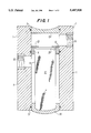
- FIG. 1 is a cross-sectional side view of an embodiment according to the invention of a filter housing with a filter cartridge mounted in it;
- FIGS. 2 and 2A are side views of a filter cartridge which is to be inserted in the filter housing indicated underneath it, and
- FIGS. 3 and 3A are cross-sectional side views of the filter housing with filter cartridge during operation with a filter cartridge pushed out underneath.
- the filtration apparatus has a vertically positioned, tubular filter housing, which comprises a short tube segment of suitable fluid-impermeable material, for example stainless steel, aluminium, or plastic, of which the tube wall 1 has a central bore, which forms a receiving chamber 2 for the filter cartridges to be inserted.
- This receiving chamber is open at both ends 3 and 4, and forms an extending channel, with which a filter cartridge can be inserted at the top side 3 and can be pushed out at the bottom side 4.
- the tubular filter housing can have any cross-section, but it is preferably circular.
- the receiving chamber 2 is provided with O-shaped rings 5 internally near both its open ends 3 and 4, while there is an O-shaped ring 6 more towards the centre.
- a fluid entrance opening 7 is provided in the tube wall 1 of the filter housing near the top end 3 of the receiving chamber, while a fluid exit opening 8 is located underneath and diametrically across the entrance 7.
- Fluid lines can be connected to the fluid entrance 7 and the fluid exit 8 by means of a threaded entrance 9 at the entrance respectively a threaded exit 10 at the exit.
- the O-shaped ring 5 is located between both O-rings 6 at a position, lying between the fluid entrance 7 and the fluid exit 8.
- a filter cartridge for use with this filtration apparatus comprises a hollow, tubular filter element 11, of which the filter wall has been reinforced with gauze or something similar, and of which the filter material encloses a filter chamber 12, which is sealed by an upper end cap 13 and a lower end cap 14.
- the circumferential sizes of these end caps are adapted to the inner diameter of the receiving chamber, so that a filter cartridge can be slided fittingly into the filter chamber 2 through the top opening 3.
- the end caps 13 and 14 are made of suitable fluid-impermeable material, and the bottom end cap 14 forms a seal for the filter chamber 12.
- a substantially annular side opening 16 is provided in the circumferential surface of the upper end cap 13, which is manufactured to be longer than the lower end cap 14. This annular opening 16 surrounds the inner space in the upper end cap, which forms a front chamber 15, which is in connection with the filter chamber 12 of the filter element 11. Some cross members 17 are required to ensure that the integrity of the upper end cap 13 is maintained.
- the entrance openings 7 and 8 for the fluid to be filtered are located at positions in the tube wall of the filter housing, such that when a filter cartridge with the end cap 14 facing downwards is inserted in the opening 3 of the filter housing till the lower end cap adjoins the bottom edge of the filter housing, the annular opening 16 of the upper end cap 13 lies in line, and therefore in connection, with the fluid entrance Y, while the filter element 11 is in open communication with the exit 8.
- the apparatus described above functions as follows. Prior to the filtration of contaminated fluid, for example, of rinsing water, containing amalgam, of a dental treatment, a filter cartridge with its end cap 14 facing downwards is slided through opening B of the filter housing into the receiving chamber 2 of the filter housing. When the filter cartridge is located in position, then the front chamber 15 in the upper end cap 13 with the annular opening 16 is in connection with the entrance 7 of the filter housing. As can be seen, the filter itself is in communication with the exit 8.
- the various sealings in the form of O-shaped rings 5 and 6 ensure that fluid, entering through Y, can only receed through 8 after having passed the filter.
- Supply and discharge lines (not shown) are connected to the entrance and the exit through screw entrances.
- a differential pressure indicator (not shown)
- a too high difference in pressure between the fluid entrance and the fluid exit indicates that the filter in operation is getting clogged such that it is not functioning properly any more
- a new filter cartridge is inserted from the top (FIG. 2).
- the used filter is pushed through with the aid of this new filter, so that it (the used filter) falls out through 4 at the underside and can be collected in a suitable container.
- the new filter is in place of the old one, and it can carry on with the intended filtering function.
- the lower end cap 14 of the filter cartridge is provided with a convex end surface 18, while the rear face 19 of the upper end cap 13 is shaped concavely in adaptation to it.
- the convex surface 18 forms a suitable aid for the insertion of a new filter cartridge on top of a used one, with this surface functioning as a "finder".
- the filter cartridges can further be provided with a one-way valve 20, which cooperates with a valve edge 21, that limits the front chamber 15 towards the filter chamber 12.
- This one-way valve is in general not required in the vertical arrangement, as shown in the embodiment, but in case one were to work with a horizontal filter housing, such a one-way valve would be very effective in preventing a reverse flow of contaminated fluid.
- the one-way valve can be of further use if the used cartridges are kept in a lying position, since there would also be a probability that the filtered contaminants could come from the filter chamber 12.
- the filter housing with a differential pressure indicator, which measures the difference in pressure between the fluid entrance and the fluid exit. When the difference in pressure becomes too large, then this indicates that the filter in operation is starting to get clogged, and that it needs to be replaced. This can, for example, be indicated by a bulb lighting up, or by a change in colour.
- the filtration apparatus according to the invention lends itself for numerous applications, especially those in which reliable and particularly hygienic filtration is required. Eventual infection hazard is reduced, in particular in medical and dental applications.
Landscapes
- Chemical & Material Sciences (AREA)
- Chemical Kinetics & Catalysis (AREA)
- Filtration Of Liquid (AREA)
- Water Treatment By Sorption (AREA)
- Electrical Discharge Machining, Electrochemical Machining, And Combined Machining (AREA)
- Infusion, Injection, And Reservoir Apparatuses (AREA)
- Processing And Handling Of Plastics And Other Materials For Molding In General (AREA)
- Separation By Low-Temperature Treatments (AREA)
- Separation Using Semi-Permeable Membranes (AREA)
Applications Claiming Priority (2)
| Application Number | Priority Date | Filing Date | Title |
|---|---|---|---|
| NL9300179A NL9300179A (nl) | 1993-01-28 | 1993-01-28 | Filterinrichting met verwisselbare filters. |
| NL9300179 | 1993-01-28 |
Publications (1)
| Publication Number | Publication Date |
|---|---|
| US5487828A true US5487828A (en) | 1996-01-30 |
Family
ID=19861996
Family Applications (1)
| Application Number | Title | Priority Date | Filing Date |
|---|---|---|---|
| US08/181,052 Expired - Fee Related US5487828A (en) | 1993-01-28 | 1994-01-14 | Filtration apparatus with exchangeable filters |
Country Status (10)
| Country | Link |
|---|---|
| US (1) | US5487828A (de) |
| EP (1) | EP0608721B1 (de) |
| JP (1) | JP3416242B2 (de) |
| AT (1) | ATE146374T1 (de) |
| CA (1) | CA2112846A1 (de) |
| DE (1) | DE69401132T2 (de) |
| DK (1) | DK0608721T3 (de) |
| ES (1) | ES2099490T3 (de) |
| GR (1) | GR3022819T3 (de) |
| NL (1) | NL9300179A (de) |
Cited By (9)
| Publication number | Priority date | Publication date | Assignee | Title |
|---|---|---|---|---|
| US5683577A (en) * | 1996-05-22 | 1997-11-04 | Nurse, Jr.; Harry L. | Filter device for wastewater treatment system |
| US20050098485A1 (en) * | 2003-10-01 | 2005-05-12 | Water Pik, Inc. | End-of-faucet filter |
| USD533622S1 (en) | 2003-10-01 | 2006-12-12 | Water Pik, Inc. | End-of-faucet filter |
| US20160123856A1 (en) * | 2013-06-12 | 2016-05-05 | Oasis Diagnostics Corporation | Rna/prtein/dna preferential fluid sample collection system and methods |
| US20160332103A1 (en) * | 2015-05-14 | 2016-11-17 | Parker-Hannifin Corporation | Pin filter |
| CN106413837A (zh) * | 2014-06-03 | 2017-02-15 | 康明斯过滤Ip公司 | 具有凸轮锁定过滤界面的过滤组件 |
| CN108325248A (zh) * | 2018-02-11 | 2018-07-27 | 马楠峰 | 滤芯 |
| CN114352223A (zh) * | 2022-03-18 | 2022-04-15 | 东营市昌瑞石油机械配件有限责任公司 | 一种井口、管道水力喷砂切割装置 |
| CN120313152A (zh) * | 2025-06-18 | 2025-07-15 | 德州隆达空调设备集团有限公司 | 一种易于更换滤芯的新风过滤装置 |
Families Citing this family (2)
| Publication number | Priority date | Publication date | Assignee | Title |
|---|---|---|---|---|
| US11975279B2 (en) * | 2012-01-12 | 2024-05-07 | Davco Technology, Llc | Fluid filter assembly with a filter cartridge and housing interface |
| US12128334B2 (en) | 2018-09-05 | 2024-10-29 | Kin Mun Chin | Filter press with threadably advanced filtrate receiving plunger |
Citations (6)
| Publication number | Priority date | Publication date | Assignee | Title |
|---|---|---|---|---|
| US2632566A (en) * | 1949-01-13 | 1953-03-24 | Sunroc Refrigeration Company | Filter control |
| US3984325A (en) * | 1975-01-06 | 1976-10-05 | Rosaen Nils O | Filter device |
| US4272368A (en) * | 1979-09-04 | 1981-06-09 | Parker-Hannifin Corporation | Fluid filter and indicator |
| FR2541131A1 (fr) * | 1983-02-21 | 1984-08-24 | Morgan Howard Jun | Filtre a panier filtrant amovible |
| US4686038A (en) * | 1982-09-29 | 1987-08-11 | Hydrotreat, Inc. | Filter apparatus |
| US5006243A (en) * | 1987-10-20 | 1991-04-09 | Hydrotreat, Inc. | Filter bag securing ring |
-
1993
- 1993-01-28 NL NL9300179A patent/NL9300179A/nl not_active Application Discontinuation
-
1994
- 1994-01-05 CA CA002112846A patent/CA2112846A1/en not_active Abandoned
- 1994-01-14 AT AT94100491T patent/ATE146374T1/de not_active IP Right Cessation
- 1994-01-14 DE DE69401132T patent/DE69401132T2/de not_active Expired - Fee Related
- 1994-01-14 ES ES94100491T patent/ES2099490T3/es not_active Expired - Lifetime
- 1994-01-14 EP EP94100491A patent/EP0608721B1/de not_active Expired - Lifetime
- 1994-01-14 US US08/181,052 patent/US5487828A/en not_active Expired - Fee Related
- 1994-01-14 DK DK94100491.3T patent/DK0608721T3/da active
- 1994-01-27 JP JP00788594A patent/JP3416242B2/ja not_active Expired - Fee Related
-
1997
- 1997-03-17 GR GR970400493T patent/GR3022819T3/el unknown
Patent Citations (6)
| Publication number | Priority date | Publication date | Assignee | Title |
|---|---|---|---|---|
| US2632566A (en) * | 1949-01-13 | 1953-03-24 | Sunroc Refrigeration Company | Filter control |
| US3984325A (en) * | 1975-01-06 | 1976-10-05 | Rosaen Nils O | Filter device |
| US4272368A (en) * | 1979-09-04 | 1981-06-09 | Parker-Hannifin Corporation | Fluid filter and indicator |
| US4686038A (en) * | 1982-09-29 | 1987-08-11 | Hydrotreat, Inc. | Filter apparatus |
| FR2541131A1 (fr) * | 1983-02-21 | 1984-08-24 | Morgan Howard Jun | Filtre a panier filtrant amovible |
| US5006243A (en) * | 1987-10-20 | 1991-04-09 | Hydrotreat, Inc. | Filter bag securing ring |
Cited By (14)
| Publication number | Priority date | Publication date | Assignee | Title |
|---|---|---|---|---|
| US5683577A (en) * | 1996-05-22 | 1997-11-04 | Nurse, Jr.; Harry L. | Filter device for wastewater treatment system |
| US20050098485A1 (en) * | 2003-10-01 | 2005-05-12 | Water Pik, Inc. | End-of-faucet filter |
| USD533622S1 (en) | 2003-10-01 | 2006-12-12 | Water Pik, Inc. | End-of-faucet filter |
| US7326334B2 (en) | 2003-10-01 | 2008-02-05 | Instapure Brands, Inc. | End-of-faucet filter |
| US20160123856A1 (en) * | 2013-06-12 | 2016-05-05 | Oasis Diagnostics Corporation | Rna/prtein/dna preferential fluid sample collection system and methods |
| CN106413837A (zh) * | 2014-06-03 | 2017-02-15 | 康明斯过滤Ip公司 | 具有凸轮锁定过滤界面的过滤组件 |
| US10226727B2 (en) | 2014-06-03 | 2019-03-12 | Cummins Filtration Ip, Inc. | Filter assembly with cam-lock filter interface |
| CN106413837B (zh) * | 2014-06-03 | 2019-08-16 | 康明斯过滤Ip公司 | 具有凸轮锁定过滤界面的过滤组件 |
| US20160332103A1 (en) * | 2015-05-14 | 2016-11-17 | Parker-Hannifin Corporation | Pin filter |
| US10150075B2 (en) * | 2015-05-14 | 2018-12-11 | Parker-Hannifin Corporation | Pin filter |
| CN108325248A (zh) * | 2018-02-11 | 2018-07-27 | 马楠峰 | 滤芯 |
| CN114352223A (zh) * | 2022-03-18 | 2022-04-15 | 东营市昌瑞石油机械配件有限责任公司 | 一种井口、管道水力喷砂切割装置 |
| CN114352223B (zh) * | 2022-03-18 | 2022-06-03 | 东营市昌瑞石油机械配件有限责任公司 | 一种井口、管道水力喷砂切割装置 |
| CN120313152A (zh) * | 2025-06-18 | 2025-07-15 | 德州隆达空调设备集团有限公司 | 一种易于更换滤芯的新风过滤装置 |
Also Published As
| Publication number | Publication date |
|---|---|
| DE69401132D1 (de) | 1997-01-30 |
| JPH07313813A (ja) | 1995-12-05 |
| ATE146374T1 (de) | 1997-01-15 |
| CA2112846A1 (en) | 1994-07-29 |
| EP0608721A1 (de) | 1994-08-03 |
| DE69401132T2 (de) | 1997-06-26 |
| EP0608721B1 (de) | 1996-12-18 |
| NL9300179A (nl) | 1994-08-16 |
| DK0608721T3 (da) | 1997-06-02 |
| JP3416242B2 (ja) | 2003-06-16 |
| ES2099490T3 (es) | 1997-05-16 |
| GR3022819T3 (en) | 1997-06-30 |
Similar Documents
| Publication | Publication Date | Title |
|---|---|---|
| US5487828A (en) | Filtration apparatus with exchangeable filters | |
| CA2113703C (en) | Water filter cartridge | |
| EP0792673B1 (de) | Wasserbehandlungsapparat | |
| US7717270B2 (en) | End-of-faucet filter | |
| US4212743A (en) | Filter | |
| US5066391A (en) | Reusable liquid filter assembly | |
| CA2215114A1 (en) | Bypass-mounted filter assembly | |
| US3358839A (en) | In-line filter element assembling means | |
| US5273650A (en) | Ceramic filter | |
| MXPA96006189A (en) | Filter of a | |
| JP2004532101A (ja) | 連動機構を有した容器カートリッジ入りフィルタと方法 | |
| JPH0477605B2 (de) | ||
| DE69623036D1 (de) | Beutelfilter und halterung dafür | |
| CA2171133C (en) | Liquid filter | |
| MY129695A (en) | Filter pitcher with ice hopper | |
| JP3527153B2 (ja) | フィルタユニットのための万能出口 | |
| US6287456B1 (en) | Filtration system with filtrate volume indicator | |
| WO2003027026A3 (de) | Filtervorrichtung mit einer uvc-lampe und mit einer reinigungseinrichtung für die uvc-lampe | |
| KR100336990B1 (ko) | 휴대용 정수기 | |
| US3608735A (en) | Spigot adapter connection for pressure hose | |
| WO1999022663A1 (en) | Filter for use with a dental instrument | |
| US4196086A (en) | Filter-purifier cartridge | |
| WO2000037363A1 (en) | Water filtration pitcher with pressure fill | |
| EP0330651A1 (de) | Aufschraubbarer patronenfilter für hydraulische systeme mit einer unter gleichbleibender seitlicher wirkung stehenden dichtung und einem druckabhängigen verschmutzungsanzeiger | |
| JPH0742550Y2 (ja) | 浄水器 |
Legal Events
| Date | Code | Title | Description |
|---|---|---|---|
| REMI | Maintenance fee reminder mailed | ||
| FPAY | Fee payment |
Year of fee payment: 4 |
|
| SULP | Surcharge for late payment | ||
| FEPP | Fee payment procedure |
Free format text: PAYOR NUMBER ASSIGNED (ORIGINAL EVENT CODE: ASPN); ENTITY STATUS OF PATENT OWNER: SMALL ENTITY |
|
| FPAY | Fee payment |
Year of fee payment: 8 |
|
| REMI | Maintenance fee reminder mailed | ||
| LAPS | Lapse for failure to pay maintenance fees | ||
| STCH | Information on status: patent discontinuation |
Free format text: PATENT EXPIRED DUE TO NONPAYMENT OF MAINTENANCE FEES UNDER 37 CFR 1.362 |
|
| FP | Lapsed due to failure to pay maintenance fee |
Effective date: 20080130 |