US5501702A - Time sharing multipolar rheography apparatus and method - Google Patents
Time sharing multipolar rheography apparatus and method Download PDFInfo
- Publication number
- US5501702A US5501702A US08/277,051 US27705194A US5501702A US 5501702 A US5501702 A US 5501702A US 27705194 A US27705194 A US 27705194A US 5501702 A US5501702 A US 5501702A
- Authority
- US
- United States
- Prior art keywords
- rheography
- circuit
- coupled
- electrodes
- pulse
- Prior art date
- Legal status (The legal status is an assumption and is not a legal conclusion. Google has not performed a legal analysis and makes no representation as to the accuracy of the status listed.)
- Expired - Lifetime
Links
Images




Classifications
-
- A—HUMAN NECESSITIES
- A61—MEDICAL OR VETERINARY SCIENCE; HYGIENE
- A61N—ELECTROTHERAPY; MAGNETOTHERAPY; RADIATION THERAPY; ULTRASOUND THERAPY
- A61N1/00—Electrotherapy; Circuits therefor
- A61N1/18—Applying electric currents by contact electrodes
- A61N1/32—Applying electric currents by contact electrodes alternating or intermittent currents
- A61N1/36—Applying electric currents by contact electrodes alternating or intermittent currents for stimulation
- A61N1/362—Heart stimulators
- A61N1/365—Heart stimulators controlled by a physiological parameter, e.g. heart potential
- A61N1/368—Heart stimulators controlled by a physiological parameter, e.g. heart potential comprising more than one electrode co-operating with different heart regions
-
- A—HUMAN NECESSITIES
- A61—MEDICAL OR VETERINARY SCIENCE; HYGIENE
- A61N—ELECTROTHERAPY; MAGNETOTHERAPY; RADIATION THERAPY; ULTRASOUND THERAPY
- A61N1/00—Electrotherapy; Circuits therefor
- A61N1/18—Applying electric currents by contact electrodes
- A61N1/32—Applying electric currents by contact electrodes alternating or intermittent currents
- A61N1/36—Applying electric currents by contact electrodes alternating or intermittent currents for stimulation
- A61N1/362—Heart stimulators
- A61N1/365—Heart stimulators controlled by a physiological parameter, e.g. heart potential
- A61N1/36514—Heart stimulators controlled by a physiological parameter, e.g. heart potential controlled by a physiological quantity other than heart potential, e.g. blood pressure
- A61N1/36521—Heart stimulators controlled by a physiological parameter, e.g. heart potential controlled by a physiological quantity other than heart potential, e.g. blood pressure the parameter being derived from measurement of an electrical impedance
Definitions
- This invention relates to the field of implantable medical devices, and more particularly relates to implantable cardiac devices such as pacemakers, defibrillators, and the like.
- Pacemakers are generally characterized by which chambers of the heart they are capable of electrically sensing, the chambers to which they deliver pacing stimuli, and their ability to respond, in their operation, to indicia of normal or abnormal cardiac functioning. Some pacemakers deliver pacing stimuli at fixed, regular intervals without regard to naturally occurring cardiac activity. More commonly, however, pacemakers sense electrical cardiac activity in one or both of the chambers of the heart, and inhibit or trigger delivery of pacing stimuli to the heart based on the occurrence and recognition of sensed intrinsic electrical events.
- a so-called "VVI” pacemaker senses electrical cardiac activity in the ventricle of the patient's heart, and delivers pacing stimuli to the ventricle only in the absence of electrical signals indicative of natural ventricular contractions.
- a "DDD" pacemaker senses electrical signals in both the atrium and ventricle of the patient's heart, and delivers atrial pacing stimuli in the absence of signals indicative of natural atrial contractions, and ventricular pacing stimuli in the absence of signals indicative of natural ventricular contractions. The delivery of each pacing stimulus by a DDD pacemaker is synchronized with prior sensed or paced events.
- Pacemakers are also known which respond to other types of physiologically-based signals, such as signals from sensors for measuring the pressure inside the patient's ventricle or for measuring the level of the patient's physical activity.
- pacemakers which measure the metabolic demand for oxygen and vary the pacing rate in response thereto have become available.
- Perhaps the most popularly employed method for measuring the need for oxygenated blood is to measure the physical activity of the patient by means of a piezoelectric transducer.
- a pacemaker is disclosed in U.S. Pat. No. 4,485,813 issued to Anderson et al.
- the pacing rate is determined according to the output from an activity sensor.
- the pacing rate is variable between a predetermined maximum and minimum level, which may be selectable by a physician from among a plurality of programmable upper and lower rate limit settings.
- the activity sensor output indicates that the patient's activity level has increased
- the pacing rate is increased from the programmed lower rate by an incremental amount which is determined as a function of the output of the activity sensor. That is, the rate-responsive or "target" pacing rate in a rate-responsive pacemaker is determined as follows:
- Target Rate Programmed Lower Rate+f(sensor output) where f is typically a linear or monotonic function of the sensor output.
- the pacing rate is periodically increased by incremental amounts calculated according to the above formula, until the programmed upper rate limit is reached.
- the pacing rate is gradually reduced, until the programmed lower rate limit is reached.
- programmable parameters In an effort to minimize patient problems and to prolong or extend the useful life of an implanted pacemaker, it has become common practice to provide numerous programmable parameters in order to permit the physician to select and/or periodically adjust the desired parameters or to match or optimize the pacing system to the patient's physiologic requirements.
- the physician may adjust the output energy settings to maximize pacemaker battery longevity while ensuring an adequate patient safety margin.
- the physician may adjust the sensing threshold to ensure adequate sensing of intrinsic depolarization of cardiac tissue, while preventing oversensing of unwanted events such as myopotential interference or electromagnetic interference (EMI).
- programmable parameters are typically required to enable and to optimize a pacemaker rate response function.
- Medtronic, Inc.'s Legend and Activitrax series of pacemakers are multiprogrammable, rate-responsive pacemakers having the following programmable parameters: pacing mode, sensitivity, refractory period, pulse amplitude, pulse width, lower and upper rate limits, rate response gain, and activity threshold.
- the sensor output correlate to as high a degree as possible with the actual metabolic and physiologic needs of the patient, so that the resulting rate-responsive pacing rate may be adjusted to appropriate levels.
- a piezoelectric activity sensor can only be used to indirectly determine the metabolic need. The physical activity sensed can be influenced by upper body motion. Therefore, an exercise that involves arm motion may provide signals that are inappropriately greater than the metabolic need. Conversely, exercises that stimulate the lower body only, such as bicycle riding, may provide a low indication of metabolic need while the actual requirement is very high. Therefore, it would be desirable to implement a rate-responsive pacemaker that is based on a parameter that is correlated directly to metabolic need.
- Minute ventilation (V c ) has been demonstrated clinically to be a parameter that correlates directly to the actual metabolic and physiologic needs of the patient. Minute ventilation is defined by the equation:
- VT tidal volume in liters.
- the measurement of V c is performed by having the patient breathe directly into a device that measures the exchange of air and computes the total volume per minute. The direct measurement of V c is not possible with an implanted device. However, V c can indirectly measured by monitoring impedance changes in the patient's thoracic cavity. Such impedance measurements can be performed with implantable circuitry and implantable leads.
- rheographic measurement involves delivering a constant current pulse between two "source” electrodes, such that the current is conducted through some region of a patient's tissue, and then measuring the voltage differential between two "recording" electrodes to ascertain the impedance of the tissue, the voltage differential arising from the conduction of the current pulse through the tissue.
- a pacemaker with rheographic capabilities can measure thoracic impedance in a patient by delivering a known current between two of the pacemaker's electrodes.
- a pacemaker capable of measuring thoracic impedance with rheography is disclosed in U.S. Pat. No. 4,702,253 issued to Nappholz et al. on Oct. 27, 1987; the Nappholz et al. patent is hereby incorporated by reference herein in its entirety.
- the magnitude of the change of the impedance signal corresponds to the tidal volume and the frequency of change corresponds to respiration rate.
- rheographic techniques allow measurement of physiological parameters without the need for a special sensor (such as the piezoelectric sensor on the canister of activity-sensing pacemakers).
- Rheographic techniques require, at most, the use of multiple electrodes located on a standard pacing lead.
- the Biorate device manufactured by Biotec International, Bologna Italy uses a bipolar (i.e., two-electrode configuration) rheographic arrangement to monitor the patient's respiratory rate.
- the Meta-MV device manufactured by Telectronics, Inc., Englewood, Colo. uses a tripolar rheographic arrangement to monitor the patient's respiratory rate.
- the Precept device manufactured by CPI, St. Paul, Minn. uses a tetrapolar rheographic arrangement to monitor the patient's pre-ejection interval (PEI), stroke volume (SV), and heart tissue contractility. It is well known that other manufacturers are exploring or have explored the use of rheographic techniques to monitor physiological parameters.
- respiration is typically measured with either a bipolar configuration in which the pacemaker's conductive canister and a large surface area electrode are used, or with a tripolar configuration using standard pacing/sensing leads having much smaller surface area electrodes. With configurations using small surface area leads, the source and recording functions must be kept spaced apart, to avoid detection of contact resistance variations. Signals representative of respiratory rate, tidal volume, and minute ventilation can be derived using bipolar or tripolar configurations.
- Detection of cardiac systole is currently believed to require a tetrapolar configuration.
- Pre-ejection interval, stroke volume, and contractility can be derived from a tetrapolar rheographic configuration.
- bipolar rheographic configurations which derive a signal that is a composite of cardiac systole effects and respiration effects, are highly susceptible to variations in the contact resistance of the electrodes.
- the contact resistance varies because respiration and cardiac systole induce a deformation on the pacing/sensing lead, thus changing the pressure of the tip electrode on the myocardial tissue. Screw-in leads reduce, but do not eliminate, the inconsistency in bipolar rheographic measurement.
- a further consideration in the selection of an electrode configuration for a pacemaker is the necessity of accurate sensing of cardiac electrical signals, including those associated with atrial contractions (i.e., "P-waves"), and those associated with ventricular contractions ("R-waves” or “QRS complexes”). Atrial sensing is especially difficult, due to the low magnitude of P-waves in relation to R-waves and the resulting problems of discriminating P-waves from R-waves. With only a single atrial electrode, the atrial signal (P-wave) detected by the atrial electrode is very similar to the ventricular signal (R-wave) appearing at that same electrode. Mere amplification of the atrial signal, therefore, does not assist in discriminating atrial from ventricular signals detected in the atrium, or in discriminating atrial signals from myopotentials or external interference.
- Atrial electrode The use of more than one atrial electrode has proven to be useful in atrial signal discrimination. This is because two atrial electrodes placed at different locations in the atrium will detect similar ventricular signals but atrial signals that are different in both amplitude and morphology.
- the electrode configuration is fixed, such that a specific function is assigned to each electrode (the electrode placement, of course, also being fixed).
- the tip electrode of the bipolar pacing/sensing lead is always "recording" (i.e., receiving current)
- the ring electrode of the lead is always the "source” (i.e., producing a current)
- the conductive pacemaker canister is always a source and recording electrode. This configuration allows measurement of impedance variation primarily due to respiration.
- the tip electrode is always the “source”
- the canister is also always the “source” and two ring electrodes on the pacing lead proximal to the tip electrode, are always “recording”. This configuration allows measurement of impedance variation primarily due to cardiac systole.
- an implantable device capable of dynamically adapting its electrode configuration for the purposes of obtaining different physiological measurements.
- an implantable cardiac stimulating device is provided with circuitry for dynamically adapting its electrode configuration so that the same electrode can serve different functions at different times.
- a pacemaker which is capable of reassigning the electrical function of a plurality of implanted electrodes such that multiple sensing configurations may be realized with a plurality of physically fixed electrodes.
- a pacemaker which is capable of performing a plurality of different sensing operations on a time-sharing basis.
- switching circuitry is provided with switching circuitry for allowing the sensing signals from a plurality of implanted electrodes may be selectively applied to sensing and detection circuitry in the pacemaker.
- Controller circuitry in the pacemaker controls the operation of the switching circuits and of a rheography current pulse generator such that a plurality of time slots are defined during a sensing interval. During successive time slots, a different electrical function may be assigned to the same electrode.
- FIG. 1 is a block diagram of a pacemaker in accordance with one embodiment of the present invention
- FIG. 2 is a schematic diagram of the switch matrices, current source, and impedance detection circuit from the pacemaker of FIG. 1;
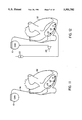
- FIG. 3 is a diagram illustrating one lead configuration for the pacemaker of FIG. 1;
- FIGS. 4, 5, 6, and 7 are diagrams illustrating four rheographic measurement configurations available with the lead configuration of FIG. 3;
- FIG. 8 is a diagram illustrating a second lead configuration for the pacemaker of FIG. 1;
- FIGS. 9 and 10 are diagrams illustrating two rheographic measurement configurations available with the lead configuration of FIG. 8;
- FIG. 11 is a diagram illustrating a third lead configuration for the pacemaker of FIG. 1;
- FIGS. 12 and 13 are diagrams illustrating two rheographic measurement configurations available with the lead configuration of FIG. 11;
- FIG. 14 is a diagram illustrating a fourth lead configuration for the pacemaker of FIG. 1;
- FIGS. 15, 16, 17, and 18 are diagrams illustrating four rheographic measurement configurations available with the lead configuration of FIG. 14.
- Pacemaker 10 operates under control of control circuitry 12 which may include a microprocessor or custom integrated circuitry, as would be appreciated by those of ordinary skill in the art.
- Control circuitry 12 is coupled to pace/sense circuitry 14 such that pace/sense circuitry 14 can provide signals to control circuitry 12 indicating the detection of electrical cardiac events (P-waves, R-waves, and the like), and such that control circuitry 12 can provide triggering signals to pace/sense circuitry 14 to initiate delivery of cardiac stimulating pulses.
- P-waves, R-waves, and the like electrical cardiac events
- control circuitry 12 and pace/sense circuitry 14 operate to detect cardiac events and deliver cardiac stimulating pulses, these circuits are of conventional and well-known design and will not be described herein in further detail. It is believed that those of ordinary skill in the art would be familiar with the design and operation of pacemaker control circuitry and pace/sense circuitry such as is included in pacemaker 10 in accordance with the presently disclosed embodiment of the invention.
- pace/sense circuitry 14 is coupled to a plurality of lead conductors designated collectively in FIG. 1 by reference numeral 16. It is to be understood that the connection between lead conductors 16 and pace/sense circuitry 14 can be implemented using any of the well-known lead connection arrangements. For example, lead conductors 16 disposed in one or more implantable pace/sense leads can be coupled to circuitry internal to pacemaker 10 by means of a conventional lead connector block disposed on the pacemaker canister. The details of connections between implantable leads and the circuitry of pacemaker 10 will not be described herein in detail, as it is believed that the manner of making such connections is well known can be readily implemented by those of ordinary skill in the art.
- Lead conductors 16 are also coupled in the pacemaker 10 of FIG. 1 to a first switch matrix 18 and a second switch matrix 20.
- switch matrix 18 establishes a selectable interconnection between particular ones of lead conductors 16 and a current source 22, for the purpose of delivering rheography pulses on lead conductors 16.
- switch matrix 20 establishes a selectable interconnection between particular ones of lead conductors 16 and an impedance detection circuit 24, for the purpose of receiving rheography pulses from lead conductors 16.
- current source 22 receives at least one control signal on line 23 issued from control circuitry 12.
- Current source 22 is responsive to control signals issued by control circuitry 12 to deliver constant current rheography pulses onto lead conductors 16.
- switching matrix 18 functions to determine which of the lead conductors 16 will receive the rheography current pulses generated by current source 22.
- the details of implementation of current source 22 are not critical to an understanding of the present invention, and it is believed that those of ordinary skill in the circuit art would be able to implement current source 22 in various ways suitable for the purposes of the present invention.
- Impedance detection circuit 24 is adapted to monitor the voltage between pairs of electrodes to which it is selectively coupled by operation of switch matrix 20, in order to determine the voltage (and hence the impedance) existing between the two electrodes. As would be appreciated by those familiar with rheographic techniques, such impedance measurement can provide an indication of various physiological events, including cardiac systole and respiratory cycles, as previously discussed.
- impedance detection circuit 24 is a differential amplifier, the implementation of which would be a matter of routine to those of ordinary skill in the circuit art.
- An analog-to-digital converter (ADC) 26 is coupled to the output of impedance detection circuit 24.
- Impedance circuit 24 produces an impedance output voltage that is proportional to the impedance between a selected pair of lead electrodes.
- ADC 26 in turn, produces a multiple-bit digital value corresponding to the analog impedance circuit output voltage. The digital impedance value is then provided to control circuit 12. It is believed that any of the various well-known and commercially available ADCs would be suitable for use in the practice of the present invention, and that no detailed description of the design and operation of ADC 26 is necessary herein.
- FIG. 2 there is shown a more detailed schematic diagram of switching circuits 18 and 20 and the interconnection of those circuits to rheographic current source 22 and impedance detection circuit 24.
- lead conductors 16 which are individually designated in FIG. 2 as 16-1 through 16-5.
- Each of the lead conductors 16 is coupled to a different electrode disposed in a sensing relationship.
- lead conductors 16-4 and 16-5 are coupled to separate ventricular electrodes on an implanted pacing/sensing lead
- conductors 16-2 and 16-3 are coupled to atrial electrodes on an implanted lead
- conductor 16-1 is coupled to the conductive pacemaker canister.
- Switching circuit 18 comprises a plurality of individual switches 18-1 through 18-10. Switches 18-1 through 18-5 selectively couple lead conductors 16-1 through 16-5, respectively, to a first input terminal 22-1 of current source 22. Switches 18-6 through 18-10 selectively couple lead conductors 16-1 through 16-5, respectively, to a second input terminal 22-2 of current source 22.
- switching circuit 20 comprises a plurality of switches 20-1 through 20-10.
- Switches 20-1 through 20-5 selectively couple lead conductors 16-1 through 16-5, respectively, to a first input terminal 24-1 of impedance detection circuit 24.
- Switches 20-6 through 20-10 selectively couple lead conductors 16-1 through 16-5, respectively, to a second input terminal 24-2 of impedance detection circuit 24.
- switching circuits 18 and 20 in FIG. 2 allows any one or more lead conductors 16 to function as a "source" of rheography current pulses. That is, any two lead conductors 16 can, with an appropriate activation of switches 18-1 through 18-10, be coupled to current source 22. Furthermore, the arrangement shown in FIG. 2 allows any one or more lead conductors 16 to "record" (i.e., receive) the rheography current pulses. That is, any two lead conductors 16 can, with an appropriate activation of switches 20-1 through 20-10, be coupled to impedance detection circuit 24.
- switches 18-1 through 18-10, and switches 20-1 through 20-10 are implemented as field-effect transistor (FET) switches which are independently actuated by gate control signals produced by control circuitry 12.
- FET field-effect transistor
- the control signals for switch matrix 18 are conducted from control circuitry 12 on a plurality of control signal lines 28, while control signals for switch matrix 20 are conducted from control circuitry 12 on a plurality of control signal lines 30.
- FET switches are presently believed to be preferred, it is contemplated that many other types of switching mechanisms may be employed in practicing the present invention.
- the rheography circuitry of pacemaker 10 is capable of operating in a multi-polar time-sharing mode wherein a plurality of rheographic pulses are generated in sequence, with the configuration of source and recording electrodes being different for each pulse delivered.
- the period of time during which rheographic measurements are to be taken e.g., the refractory period preceding delivery of a stimulating pulse, as discussed in the aforementioned Lampadius patent
- Switches 18 and 20 are operated in timed synchronism with the delivery of a sequence of rheographic current pulses from current source 22 such that a rheographic pulse is delivered to a different source/recording electrode configuration during each time slot.
- Such operation of the rheography circuitry in pacemaker 10 will be better appreciated with reference to some specific example configurations to be hereinafter described.
- time slots of between 0.01 to 100-Msec or so duration may be defined.
- the state of switches 18 and 20 determine what type of rheographic measurement is to be taken. It is believed that the length of time slots can vary from implementation to implementation.
- pacemaker 10 With reference now to FIG. 3, a particular configuration of pacemaker 10 is depicted.
- pacemaker 10 and lead 16 are shown in relation to a patient's heart 32.
- lead 16 is a standard quadripolar lead having, as shown, two atrial ring electrodes A1 and A2 and two ventricular electrodes V1 and V2.
- lead configuration is a conventional one for pacing in the VDD pacing mode, with bipolar ventricular sensing.
- the pacemaker canister serves as both a source and recording electrode; atrial electrode A2 serves as a recording electrode, and atrial electrode A1 serves as a source electrode.
- the correspondence between the electrodes and the lead conductors shown in FIG. 2 is assumed to be as set forth in the following Table 2:
- Time Slot 1-0 the configuration during Time Slot 1-0 is realized by closing switches 18-1 and 18-8, as well as switches 20-1 and 20-7, leaving all other switches open.
- current source 22 is coupled to the pacemaker canister and to atrial electrode A1
- impedance detection circuit 24 is coupled to the pacemaker canister and to atrial electrode A2.
- Time Slot 1-1 the pacemaker canister again serves as both a recording and source electrode.
- Ventricular electrode V2 serves as a source electrode
- ventricular electrode V1 serves as a recording electrode. This is achieved by closing switches 18-1 and 18-9, along with switches 20-1 and 20-10, again leaving all other switches open.
- the effective configuration of Time Slot 1-1 is shown in FIG. 5.
- Current source 22 is coupled to the pacemaker canister and to electrode V2, while impedance detection circuit 24 is coupled to the pacemaker canister and to ventricular electrode V1.
- transthoracic impedance is measured using the tripolar configuration used by the aforementioned Telectronics Meta-MV pacemaker.
- the pacemaker canister and ventricular electrode V2 serve as source electrodes, while the two atrial electrodes A1 and A2 serve as recording electrodes.
- This configuration realized by closing switches 18-1 and 18-9, as well as switches 20-2 and 20-8, is depicted in FIG. 6.
- atrial intracardiac impedance is measured.
- Atrial electrode A2 and ventricular electrode V2 serve as source electrodes, while atrial electrode A1 and ventricular electrode V1 serve as recording electrodes.
- This configuration realized by closing switches 18-2 and 18-9, along with switches 20-3 and 20-10, is depicted in FIG. 7.
- ventricular intracardiac impedance is measured.
- FIG. 8 there is shown a second example configuration which utilizes a standard tripolar lead having two atrial electrodes and one ventricular electrode.
- the configuration of FIG. 8 is a conventional one for performing VDD pacing with unipolar ventricular sensing.
- the pacemaker canister functions as both a source and a recording electrode.
- Atrial electrode A2 serves as a recording electrode
- atrial electrode A1 serves as a source electrode.
- This configuration achieved by closing switches 18-1 and 18-8 and switches 20-1 and 20-7, is depicted in FIG. 9.
- transthoracic impedance is measured.
- Time Slot 2-1 the pacemaker canister and ventricular electrode V1 serve as source electrodes, while the two atrial electrodes A2 and A1 serve as recording electrodes. This is accomplished by closing switches 18-1 and 18-10, along with switches 20-2 and 20-8. (It is to be understood that since there is only a single ventricular electrode in the example configuration of FIG. 8, switches 18-4, 18-9, 20-4, and 20-9 associated with the second ventricular electrode (see FIG. 2) are not used.)
- the configuration corresponding to Time Slot 2-1 is depicted in FIG. 10. With this configuration, atrial transthoracic impedance is measured.
- FIG. 11 there is shown a third example configuration of pacemaker 10 in accordance with the presently disclosed embodiment of the invention.
- a standard tripolar lead is used.
- This arrangement is suitable for performing VVI pacing with tripolar ventricular sensing.
- This arrangement also allows for quadripolar rheographic measurement in two time slots.
- the two time slots are defined for the configuration of FIG. 11 as set forth in the following Table 5:
- Time Slot 3-0 the canister serves as both source and recording electrode; ventricular electrode V3 serves as a recording electrode, and ventricular electrode V2 serves as a source electrode.
- the configuration of Time Slot 3-0 achieved by closing switches 18-1 and 18-9 along with switches 20-1 and 20-8, is depicted in FIG. 12. With the configuration of FIG. 12, transthoracic impedance is measured.
- Time Slot 3-1 the canister serves as a source electrode, electrodes V3 and V2 serve as recording electrodes, and electrode V1 serves as a source electrode.
- the configuration of Time Slot 3-1 achieved by closing switches 18-1 and 18-10 along with switches 20-3 and 20-9, is depicted in FIG. 13. With the configuration of FIG. 13, atrial intracardiac impedance is measured.
- FIG. 14 there is shown a fourth example configuration for pacemaker 10 in accordance with the presently disclosed embodiment of the invention.
- the configuration of FIG. 14 utilizes two bipolar leads, one atrial and one ventricular.
- this lead configuration is a conventional one for performing DDD pacing with bipolar atrial and ventricular sensing.
- five-pole rheographic measurement is possible in four time slots. The configuration during each time slot is set forth in the following Table 7:
- the canister serves as both a source and a recording electrode.
- Atrial electrode A2 serves as a recording electrode and electrode A1 serves as a source electrode.
- This configuration achieved by closing switches 18-1 and 18-8 along with switches 20-1 and 20-7, is depicted in FIG. 15. With this configuration, transthoracic impedance is measured.
- the canister again serves as both a source and a recording electrode.
- Ventricular electrode V2 serves as a source electrode
- ventricular electrode V1 serves as a recording electrode.
- This configuration achieved by closing switches 18-1 and 18-9 along with switches 20-1 and 20-10, is depicted in FIG. 16. With this configuration, transthoracic impedance is measured in the same manner as in the above-noted Telectronics Meta-MV device.
- the canister and ventricular electrode V2 serve as source electrodes, while electrodes A2 and A1 are recording electrodes.
- This configuration achieved by closing switches 18-1 and 18-9 as well as switches 20-2 and 20-8, is depicted in FIG. 17. With this configuration, atrial intracardiac impedance is measured.
- electrodes A2 and V2 serve as source electrodes, while electrodes A1 and V1 serve as recording electrodes.
- This configuration achieved by closing switches 18-2, 18-9, 20-3 and 20-10, is depicted in FIG. 18. With this configuration, ventricular intracardiac impedance is measured.
- pacemaker 10 in accordance with the presently disclosed embodiment of the invention is capable of dynamically reassigning the electrical function of the leads and electrodes coupled thereto, so that a plurality of rheographic measurement configurations can be realized.
- the present invention may be advantageously practiced in conjunction with any of the different types of pacemakers (VVI, VDD, DDD, etc . . .) and with any of the different types of standard pacemaker pace/sense leads (bipolar, tripolar, etc . . .). It is believed that, with the benefit of the present disclosure, those of ordinary skill in the pacemaker art would be able to readily adapt the present invention to be practiced with any number of lead conductors.
- the present invention enables the pacemaker to perform a different rheographic measurement during each of a plurality of time slots defined in an appropriate rheography interval.
- the number of time slots can vary depending upon the number of electrodes and upon the desired rheographic configurations to be used.
Landscapes
- Health & Medical Sciences (AREA)
- Cardiology (AREA)
- Heart & Thoracic Surgery (AREA)
- Life Sciences & Earth Sciences (AREA)
- Biophysics (AREA)
- Physiology (AREA)
- Engineering & Computer Science (AREA)
- Biomedical Technology (AREA)
- Nuclear Medicine, Radiotherapy & Molecular Imaging (AREA)
- Radiology & Medical Imaging (AREA)
- Animal Behavior & Ethology (AREA)
- General Health & Medical Sciences (AREA)
- Public Health (AREA)
- Veterinary Medicine (AREA)
- Hematology (AREA)
- Electrotherapy Devices (AREA)
- Percussion Or Vibration Massage (AREA)
- Prostheses (AREA)
Applications Claiming Priority (2)
| Application Number | Priority Date | Filing Date | Title |
|---|---|---|---|
| ITRM940356A IT1272265B (it) | 1994-06-06 | 1994-06-06 | Perfezionamento nei sistemi stimolatori cardiaci |
| ITRM94A0356 | 1994-06-06 |
Publications (1)
| Publication Number | Publication Date |
|---|---|
| US5501702A true US5501702A (en) | 1996-03-26 |
Family
ID=11402581
Family Applications (1)
| Application Number | Title | Priority Date | Filing Date |
|---|---|---|---|
| US08/277,051 Expired - Lifetime US5501702A (en) | 1994-06-06 | 1994-07-19 | Time sharing multipolar rheography apparatus and method |
Country Status (2)
| Country | Link |
|---|---|
| US (1) | US5501702A (it) |
| IT (1) | IT1272265B (it) |
Cited By (78)
| Publication number | Priority date | Publication date | Assignee | Title |
|---|---|---|---|---|
| WO1998019738A1 (en) * | 1996-11-05 | 1998-05-14 | Medtronic, Inc. | Cardioversion/defibrillation lead impedance measurement system |
| WO1999030777A1 (en) | 1997-12-15 | 1999-06-24 | Medtronic, Inc. | Four-chamber pacing system for optimizing cardiac output |
| WO1999037360A1 (en) * | 1998-01-23 | 1999-07-29 | Intermedics Inc. | Implantable cardiac stimulator with safe noise mode |
| WO2000078391A1 (en) * | 1999-06-21 | 2000-12-28 | Cardiac Pacemakers, Inc. | Multi-site impedance sensor using coronary sinus/vein electrodes |
| EP1116497A1 (fr) * | 2000-01-14 | 2001-07-18 | Ela Medical | Dispositif médical implantable actif, notamment stimulateur cardiaque, défibrillateur et/ou dispositif multisite comportant des moyens de mesure d'impédance transvalvulaire |
| EP1132109A1 (fr) | 2000-03-07 | 2001-09-12 | Ela Medical | Stimulateur implantable du type multisite comportant des moyens de mesure d'impédance intracardiaque |
| WO2001087410A3 (en) * | 2000-05-15 | 2002-03-21 | Pacesetter Inc | Cardiac stimulation devices and methods for measuring impedances associated with the left side of the heart |
| US6473645B1 (en) | 2001-04-12 | 2002-10-29 | Pacesetter, Inc. | System and method for programmably controlling electrode activation sequence in a multi-site cardiac stimulation device |
| US20020198570A1 (en) * | 1997-08-26 | 2002-12-26 | Puskas John D. | Apparatus for indirectly stimulating the vagus nerve with an electrical field |
| US20030074039A1 (en) * | 1999-06-25 | 2003-04-17 | Puskas John D. | Devices and methods for vagus nerve stimulation |
| US20030105496A1 (en) * | 2001-12-05 | 2003-06-05 | Cardiac Pacemakers, Inc. | Cardiac resynchronization system employing mechanical measurement of cardiac walls |
| US20030114889A1 (en) * | 2000-07-14 | 2003-06-19 | Cardiac Pacemakers, Inc. | Method and apparatuses for monitoring hemodynamic activities using an intracardiac impedance-derived parameter |
| US20030195579A1 (en) * | 2002-04-16 | 2003-10-16 | Kerry Bradley | Automatic capture using independent channels in bi-chamber stimulation |
| US20030204212A1 (en) * | 2002-04-29 | 2003-10-30 | Burnes John E. | Algorithm for the automatic determination of optimal AV and VV intervals |
| US20030208236A1 (en) * | 2002-05-06 | 2003-11-06 | Cardiac Pacemakers, Inc. | System and method for providing temporary stimulation therapy to optimize chronic electrical performance for electrodes used in conjunction with a cardiac rhythm management system |
| US6684101B2 (en) | 2001-04-25 | 2004-01-27 | Cardiac Pacemakers, Inc. | Implantable medical device employing single drive, dual sense impedance measuring |
| US20040024422A1 (en) * | 2000-09-26 | 2004-02-05 | Hill Michael R.S. | Method and system for sensing cardiac contractions during a medical procedure |
| US6725091B2 (en) | 2000-03-14 | 2004-04-20 | Ela Medical S.A. | Measuring a trans-septum bio-impedance in an active implantable medical device, in a particular pacemaker, defibrillator and/or cadiovertor and/or multisite device |
| US20040102712A1 (en) * | 2002-11-25 | 2004-05-27 | Andres Belalcazar | Impedance monitoring for detecting pulmonary edema and thoracic congestion |
| US20040111118A1 (en) * | 2000-09-26 | 2004-06-10 | Hill Michael R.S. | Method and system for spinal cord stimulation prior to and during a medical procedure |
| US20040116820A1 (en) * | 2002-12-13 | 2004-06-17 | Daum Douglas R. | Respiration signal measurement apparatus, systems, and methods |
| US20040172075A1 (en) * | 1996-04-30 | 2004-09-02 | Shafer Lisa L. | Method and system for vagal nerve stimulation with multi-site cardiac pacing |
| US20040186517A1 (en) * | 1996-04-30 | 2004-09-23 | Hill Michael R.S. | Method and system for nerve stimulation prior to and during a medical procedure |
| US20040199209A1 (en) * | 2003-04-07 | 2004-10-07 | Hill Michael R.S. | Method and system for delivery of vasoactive drugs to the heart prior to and during a medical procedure |
| US20050049644A1 (en) * | 2001-11-21 | 2005-03-03 | Cameron Health, Inc. | Multiple electrode vectors for implantable cardiac treatment devices |
| US20050096707A1 (en) * | 2000-09-26 | 2005-05-05 | Medtronic, Inc. | Method and system for monitoring and controlling systemic and pulmonary circulation during a medical procedure |
| US20050124908A1 (en) * | 2003-12-03 | 2005-06-09 | Andres Belalcazar | Monitoring thoracic fluid changes |
| US20060001070A1 (en) * | 2004-05-03 | 2006-01-05 | Samsung Electronics Co., Ltd. | Capacitor of a memory device and fabrication method thereof |
| US20060025828A1 (en) * | 2004-07-28 | 2006-02-02 | Armstrong Randolph K | Impedance measurement for an implantable device |
| US20060064027A1 (en) * | 2004-09-21 | 2006-03-23 | Borowitz Lynn A | Implantable medical device with his-purkinje activity detection |
| US7092757B2 (en) | 2002-07-12 | 2006-08-15 | Cardiac Pacemakers, Inc. | Minute ventilation sensor with dynamically adjusted excitation current |
| US20060184060A1 (en) * | 2005-02-15 | 2006-08-17 | Andres Belalcazar | Pathology assessment with impedance measurements using convergent bioelectric lead fields |
| US7130682B2 (en) | 2000-12-26 | 2006-10-31 | Cardiac Pacemakers, Inc. | Pacing and sensing vectors |
| US20060271117A1 (en) * | 2005-05-24 | 2006-11-30 | Burnes John E | Algorithm for the automatic determination of optimal pacing intervals |
| US20070027485A1 (en) * | 2005-07-29 | 2007-02-01 | Kallmyer Todd A | Implantable medical device bus system and method |
| US20070100407A1 (en) * | 2005-10-28 | 2007-05-03 | Cyberonics, Inc. | Lead condition assessment for an implantable medical device |
| US20070118042A1 (en) * | 2003-04-25 | 2007-05-24 | Li Wang | Method and apparatus for impedance signal localizations from implanted devices |
| US20070179557A1 (en) * | 2006-01-27 | 2007-08-02 | Maschino Steven E | Controlling neuromodulation using stimulus modalities |
| US20070244535A1 (en) * | 2006-04-18 | 2007-10-18 | Cyberonics, Inc. | Heat dissipation for a lead assembly |
| US20070276445A1 (en) * | 2006-05-26 | 2007-11-29 | Cameron Health, Inc. | Systems and methods for sensing vector selection in an implantable medical device |
| US20070276452A1 (en) * | 2006-05-26 | 2007-11-29 | Cameron Health, Inc. | Implantable medical device systems having initialization functions and methods of operation |
| US7305266B1 (en) | 2001-05-14 | 2007-12-04 | Pacesetter, Inc. | Cardiac stimulation devices and methods for measuring impedances associated with the heart |
| US20080015641A1 (en) * | 2006-07-12 | 2008-01-17 | Cyberonics, Inc. | Implantable Medical Device Charge Balance Assessment |
| US20080114410A1 (en) * | 2005-05-25 | 2008-05-15 | Cardiac Pacemakers, Inc. | Closed loop impedance-based cardiac resynchronization therapy systems, devices, and methods |
| US20080172100A1 (en) * | 2007-01-16 | 2008-07-17 | Cameron Health, Inc. | Systems and methods for sensing vector selection in an implantable medical device using a polynomial approach |
| US20080183258A1 (en) * | 2007-01-26 | 2008-07-31 | Inman D Michael | Electrode assembly with fibers for a medical device |
| US20080188901A1 (en) * | 2007-02-07 | 2008-08-07 | Cameron Health, Inc. | Sensing vector selection in a cardiac stimulus device with postural assessment |
| US20080275521A1 (en) * | 2003-07-28 | 2008-11-06 | Cameron Health, Inc. | Vector Switching in an Implantable Cardiac Stimulus System |
| US20090112292A1 (en) * | 2007-10-26 | 2009-04-30 | Cyberonics Inc. | Dynamic lead condition detection for an implantable medical device |
| US20090125079A1 (en) * | 2007-10-26 | 2009-05-14 | Cyberonics Inc. | Alternative operation mode for an implantable medical device based upon lead condition |
| US7623909B2 (en) | 2006-05-26 | 2009-11-24 | Cameron Health, Inc. | Implantable medical devices and programmers adapted for sensing vector selection |
| US20100004708A1 (en) * | 1996-04-30 | 2010-01-07 | Medtronic, Inc. | Method and system for nerve stimulation and cardiac sensing prior to and during a medical procedure |
| US7657310B2 (en) | 2006-01-26 | 2010-02-02 | Cyberonics, Inc. | Treatment of reproductive endocrine disorders by vagus nerve stimulation |
| US20100192374A1 (en) * | 2006-07-26 | 2010-08-05 | Cyberonics, Inc. | Multi-Electrode Assembly for an Implantable Medical Device |
| US20100268102A1 (en) * | 2007-12-19 | 2010-10-21 | St. Jude Medical Ab | Implantable heart monitoring device, system and method |
| US7957796B2 (en) | 2005-10-28 | 2011-06-07 | Cyberonics, Inc. | Using physiological sensor data with an implantable medical device |
| WO2012057867A1 (en) | 2010-10-29 | 2012-05-03 | Medtronic, Inc. | Cardiac therapy based upon impedance signals |
| US8306621B2 (en) | 2003-07-02 | 2012-11-06 | Cardiac Pacemakers, Inc. | Cardiac cycle synchronized sampling of impedance signal |
| US8406868B2 (en) | 2010-04-29 | 2013-03-26 | Medtronic, Inc. | Therapy using perturbation and effect of physiological systems |
| RU2479871C1 (ru) * | 2012-02-07 | 2013-04-20 | ГБОУ ВПО "Смоленская государственная медицинская академия" Министерства здравоохранения и социального развития Российской Федерации | Способ регистрации механической работы изолированного сердца лягушки |
| CN101732795B (zh) * | 2008-11-21 | 2013-06-12 | 深圳迈瑞生物医疗电子股份有限公司 | 起搏发生装置及其控制方法 |
| US8478428B2 (en) | 2010-04-23 | 2013-07-02 | Cyberonics, Inc. | Helical electrode for nerve stimulation |
| US8620425B2 (en) | 2010-04-29 | 2013-12-31 | Medtronic, Inc. | Nerve signal differentiation in cardiac therapy |
| US8639327B2 (en) | 2010-04-29 | 2014-01-28 | Medtronic, Inc. | Nerve signal differentiation in cardiac therapy |
| US8706223B2 (en) | 2011-01-19 | 2014-04-22 | Medtronic, Inc. | Preventative vagal stimulation |
| US8718763B2 (en) | 2011-01-19 | 2014-05-06 | Medtronic, Inc. | Vagal stimulation |
| US8725259B2 (en) | 2011-01-19 | 2014-05-13 | Medtronic, Inc. | Vagal stimulation |
| US8781583B2 (en) | 2011-01-19 | 2014-07-15 | Medtronic, Inc. | Vagal stimulation |
| US8781582B2 (en) | 2011-01-19 | 2014-07-15 | Medtronic, Inc. | Vagal stimulation |
| US8868185B2 (en) | 2011-10-31 | 2014-10-21 | Medtronic, Inc. | Use of thoracic and extra-thoracic impedance for diagnostic monitoring |
| WO2015109071A1 (en) | 2014-01-17 | 2015-07-23 | Medtronic, Inc. | Cardiac resynchronization therapy optimization based on intracardiac impedance |
| US9089276B2 (en) | 2013-03-15 | 2015-07-28 | Pacesetter, Inc. | Systems and methods for obtaining substantially simultaneous mult-channel impedance measurements and related applications |
| US9387330B2 (en) | 2014-01-17 | 2016-07-12 | Medtronic, Inc. | Cardiac resynchronization therapy optimization based on intracardiac impedance and heart sounds |
| US9579065B2 (en) | 2013-03-12 | 2017-02-28 | Cameron Health Inc. | Cardiac signal vector selection with monophasic and biphasic shape consideration |
| US9597511B2 (en) | 2011-10-31 | 2017-03-21 | Medtronic, Inc. | Method to assess hemodynamic performance during cardiac resynchronization therapy optimization using admittance waveforms and derivatives |
| US9839781B2 (en) | 2005-08-22 | 2017-12-12 | Cardiac Pacemakers, Inc. | Intracardiac impedance and its applications |
| WO2020154906A1 (zh) * | 2019-01-29 | 2020-08-06 | 深圳市科曼医疗设备有限公司 | 一种动态电压调整的恒流刺激电路 |
| RU227165U1 (ru) * | 2024-01-23 | 2024-07-09 | Акционерное Общество "Амт" (Ао "Амт") | Электромиостимулятор |
Citations (4)
| Publication number | Priority date | Publication date | Assignee | Title |
|---|---|---|---|---|
| US4485813A (en) * | 1981-11-19 | 1984-12-04 | Medtronic, Inc. | Implantable dynamic pressure transducer system |
| US4702253A (en) * | 1985-10-15 | 1987-10-27 | Telectronics N.V. | Metabolic-demand pacemaker and method of using the same to determine minute volume |
| US4721110A (en) * | 1984-08-06 | 1988-01-26 | Lampadius Michael S | Respiration-controlled cardiac pacemaker |
| US5052388A (en) * | 1989-12-22 | 1991-10-01 | Medtronic, Inc. | Method and apparatus for implementing activity sensing in a pulse generator |
-
1994
- 1994-06-06 IT ITRM940356A patent/IT1272265B/it active IP Right Grant
- 1994-07-19 US US08/277,051 patent/US5501702A/en not_active Expired - Lifetime
Patent Citations (4)
| Publication number | Priority date | Publication date | Assignee | Title |
|---|---|---|---|---|
| US4485813A (en) * | 1981-11-19 | 1984-12-04 | Medtronic, Inc. | Implantable dynamic pressure transducer system |
| US4721110A (en) * | 1984-08-06 | 1988-01-26 | Lampadius Michael S | Respiration-controlled cardiac pacemaker |
| US4702253A (en) * | 1985-10-15 | 1987-10-27 | Telectronics N.V. | Metabolic-demand pacemaker and method of using the same to determine minute volume |
| US5052388A (en) * | 1989-12-22 | 1991-10-01 | Medtronic, Inc. | Method and apparatus for implementing activity sensing in a pulse generator |
Cited By (184)
| Publication number | Priority date | Publication date | Assignee | Title |
|---|---|---|---|---|
| US20040186517A1 (en) * | 1996-04-30 | 2004-09-23 | Hill Michael R.S. | Method and system for nerve stimulation prior to and during a medical procedure |
| US20040172075A1 (en) * | 1996-04-30 | 2004-09-02 | Shafer Lisa L. | Method and system for vagal nerve stimulation with multi-site cardiac pacing |
| US8036741B2 (en) | 1996-04-30 | 2011-10-11 | Medtronic, Inc. | Method and system for nerve stimulation and cardiac sensing prior to and during a medical procedure |
| US20100004708A1 (en) * | 1996-04-30 | 2010-01-07 | Medtronic, Inc. | Method and system for nerve stimulation and cardiac sensing prior to and during a medical procedure |
| US7184829B2 (en) | 1996-04-30 | 2007-02-27 | Medtronic, Inc. | Method and system for nerve stimulation prior to and during a medical procedure |
| US7269457B2 (en) | 1996-04-30 | 2007-09-11 | Medtronic, Inc. | Method and system for vagal nerve stimulation with multi-site cardiac pacing |
| WO1998019738A1 (en) * | 1996-11-05 | 1998-05-14 | Medtronic, Inc. | Cardioversion/defibrillation lead impedance measurement system |
| US7310552B2 (en) | 1997-08-26 | 2007-12-18 | Puskas John D | Apparatus for indirectly stimulating the vagus nerve with an electrical field |
| US20020198570A1 (en) * | 1997-08-26 | 2002-12-26 | Puskas John D. | Apparatus for indirectly stimulating the vagus nerve with an electrical field |
| US6238420B1 (en) | 1997-12-15 | 2001-05-29 | Medtronic Inc. | Four-chamber pacing system for optimizing cardiac output and determining heart condition |
| US6223082B1 (en) | 1997-12-15 | 2001-04-24 | Medtronic Inc. | Four-chamber pacing system for optimizing cardic output and determining heart condition |
| US6070100A (en) * | 1997-12-15 | 2000-05-30 | Medtronic Inc. | Pacing system for optimizing cardiac output and determining heart condition |
| EP1477204A1 (en) | 1997-12-15 | 2004-11-17 | Medtronic Inc. | Four-chamber pacing system for optimizing cardiac output |
| US6219579B1 (en) | 1997-12-15 | 2001-04-17 | Medtronic Inc. | Four-chamber pacing system for optimizing cardiac output and determining heart condition |
| US6223079B1 (en) | 1997-12-15 | 2001-04-24 | Medtronic, Inc | Bi-ventricular pacing method |
| WO1999030777A1 (en) | 1997-12-15 | 1999-06-24 | Medtronic, Inc. | Four-chamber pacing system for optimizing cardiac output |
| US6754530B2 (en) | 1997-12-15 | 2004-06-22 | Medtronic, Inc. | Four-chamber pacing system for optimizing cardiac output and determining heart condition |
| WO1999037360A1 (en) * | 1998-01-23 | 1999-07-29 | Intermedics Inc. | Implantable cardiac stimulator with safe noise mode |
| US6198968B1 (en) | 1998-01-23 | 2001-03-06 | Intermedics Inc. | Implantable cardiac stimulator with safe noise mode |
| WO2000078391A1 (en) * | 1999-06-21 | 2000-12-28 | Cardiac Pacemakers, Inc. | Multi-site impedance sensor using coronary sinus/vein electrodes |
| US6278894B1 (en) | 1999-06-21 | 2001-08-21 | Cardiac Pacemakers, Inc. | Multi-site impedance sensor using coronary sinus/vein electrodes |
| US20030074039A1 (en) * | 1999-06-25 | 2003-04-17 | Puskas John D. | Devices and methods for vagus nerve stimulation |
| US6604002B2 (en) | 2000-01-14 | 2003-08-05 | Ela Medical S.A. | Measuring the trans-valvular bio-impedance in an active implantable medical device, in particular a pacemaker, defibrillator and/or cardiovertor and/or multisite device |
| EP1116497A1 (fr) * | 2000-01-14 | 2001-07-18 | Ela Medical | Dispositif médical implantable actif, notamment stimulateur cardiaque, défibrillateur et/ou dispositif multisite comportant des moyens de mesure d'impédance transvalvulaire |
| FR2803759A1 (fr) * | 2000-01-14 | 2001-07-20 | Ela Medical Sa | Dispositif medical implantable actif, notamment stimulateur cardiaque, defibrillateur et/ou dispositif multisite comportant des moyens de mesure d'impedance transvalvulaire |
| FR2805998A1 (fr) * | 2000-03-07 | 2001-09-14 | Ela Medical Sa | Dispositif medical implantable actif, notamment stimulateur cardiaque, defibrillateur et/ou cardioverteur du type multisite comportant des moyens de mesure d'impedance intracardiaque |
| US6539261B2 (en) | 2000-03-07 | 2003-03-25 | Ela Medical, S.A. | Measurement of intracardiac impedance in a multisite-type, active implantable medical device, in particular a pacemaker, defibrillator and/or cardiovertor |
| EP1132109A1 (fr) | 2000-03-07 | 2001-09-12 | Ela Medical | Stimulateur implantable du type multisite comportant des moyens de mesure d'impédance intracardiaque |
| US6725091B2 (en) | 2000-03-14 | 2004-04-20 | Ela Medical S.A. | Measuring a trans-septum bio-impedance in an active implantable medical device, in a particular pacemaker, defibrillator and/or cadiovertor and/or multisite device |
| WO2001087410A3 (en) * | 2000-05-15 | 2002-03-21 | Pacesetter Inc | Cardiac stimulation devices and methods for measuring impedances associated with the left side of the heart |
| US7062326B2 (en) | 2000-07-14 | 2006-06-13 | Cardiac Pacemakers, Inc. | Method and apparatuses for monitoring hemodynamic activities using an intracardiac impedance-derived parameter |
| US20030114889A1 (en) * | 2000-07-14 | 2003-06-19 | Cardiac Pacemakers, Inc. | Method and apparatuses for monitoring hemodynamic activities using an intracardiac impedance-derived parameter |
| US20040024422A1 (en) * | 2000-09-26 | 2004-02-05 | Hill Michael R.S. | Method and system for sensing cardiac contractions during a medical procedure |
| US20050096707A1 (en) * | 2000-09-26 | 2005-05-05 | Medtronic, Inc. | Method and system for monitoring and controlling systemic and pulmonary circulation during a medical procedure |
| US7184828B2 (en) | 2000-09-26 | 2007-02-27 | Medtronic, Inc. | Method and system for spinal cord stimulation prior to and during a medical procedure |
| US20040111118A1 (en) * | 2000-09-26 | 2004-06-10 | Hill Michael R.S. | Method and system for spinal cord stimulation prior to and during a medical procedure |
| US20070208381A1 (en) * | 2000-09-26 | 2007-09-06 | Medtronic, Inc. | Method and system for spinal cord stimulation prior to and during a medical procedure |
| US7130682B2 (en) | 2000-12-26 | 2006-10-31 | Cardiac Pacemakers, Inc. | Pacing and sensing vectors |
| US8798744B2 (en) | 2001-02-08 | 2014-08-05 | Cardiac Pacemakers, Inc. | Pacing and sensing vectors |
| US7991468B2 (en) | 2001-02-08 | 2011-08-02 | Cardiac Pacemakers, Inc. | Pacing and sensing vectors |
| US20070055313A1 (en) * | 2001-02-08 | 2007-03-08 | Cardiac Pacemakers, Inc. | Pacing and sensing vectors |
| US20070049978A1 (en) * | 2001-02-08 | 2007-03-01 | Cardiac Pacemakers, Inc. | Pacing and sensing vectors |
| US9278221B2 (en) | 2001-02-08 | 2016-03-08 | Cardiac Pacemakers, Inc. | Pacing and sensing vectors |
| US7945325B2 (en) | 2001-02-08 | 2011-05-17 | Cardiac Pacemakers, Inc. | Pacing and sensing vectors |
| US6473645B1 (en) | 2001-04-12 | 2002-10-29 | Pacesetter, Inc. | System and method for programmably controlling electrode activation sequence in a multi-site cardiac stimulation device |
| US6477417B1 (en) | 2001-04-12 | 2002-11-05 | Pacesetter, Inc. | System and method for automatically selecting electrode polarity during sensing and stimulation |
| US6606516B2 (en) | 2001-04-12 | 2003-08-12 | Pacesetter, Inc. | System and method for programmably controlling stimulation electrode configurations and activation sequence in a multi-site cardiac stimulation device |
| US6684101B2 (en) | 2001-04-25 | 2004-01-27 | Cardiac Pacemakers, Inc. | Implantable medical device employing single drive, dual sense impedance measuring |
| US7305266B1 (en) | 2001-05-14 | 2007-12-04 | Pacesetter, Inc. | Cardiac stimulation devices and methods for measuring impedances associated with the heart |
| US20050192507A1 (en) * | 2001-11-21 | 2005-09-01 | Cameron Health, Inc. | Multiple electrode vectors for implantable cardiac treatment devices |
| US7392085B2 (en) | 2001-11-21 | 2008-06-24 | Cameron Health, Inc. | Multiple electrode vectors for implantable cardiac treatment devices |
| US20050049644A1 (en) * | 2001-11-21 | 2005-03-03 | Cameron Health, Inc. | Multiple electrode vectors for implantable cardiac treatment devices |
| US7627367B2 (en) | 2001-11-21 | 2009-12-01 | Cameron Health, Inc. | Multiple electrode vectors for implantable cardiac treatment devices |
| US20030105496A1 (en) * | 2001-12-05 | 2003-06-05 | Cardiac Pacemakers, Inc. | Cardiac resynchronization system employing mechanical measurement of cardiac walls |
| US20070129781A1 (en) * | 2001-12-05 | 2007-06-07 | Cardiac Pacemakers Inc. | Cardiac resynchronization system employing mechanical measurement of cardiac walls |
| US8792980B2 (en) | 2001-12-05 | 2014-07-29 | Cardiac Pacemakers, Inc. | Cardiac resynchronization system employing mechanical measurement of cardiac walls |
| US7127289B2 (en) | 2001-12-05 | 2006-10-24 | Cardiac Pacemakers, Inc. | Cardiac resynchronization system employing mechanical measurement of cardiac walls |
| US7904155B2 (en) | 2001-12-05 | 2011-03-08 | Cardiac Pacemakers, Inc. | Cardiac resynchronization method and apparatus employing mechanical measurement of cardiac walls |
| US20110093031A1 (en) * | 2001-12-05 | 2011-04-21 | Yinghong Yu | Cardiac resynchronization system employing mechanical measurement of cardiac walls |
| US6915164B2 (en) | 2002-04-16 | 2005-07-05 | Pacesetter, Inc. | Automatic capture using independent channels in bi-chamber stimulation |
| US20030195579A1 (en) * | 2002-04-16 | 2003-10-16 | Kerry Bradley | Automatic capture using independent channels in bi-chamber stimulation |
| US20070213778A1 (en) * | 2002-04-29 | 2007-09-13 | Burnes John E | Algorithm for the automatic determination of optimal av and vv intervals |
| US8135463B2 (en) | 2002-04-29 | 2012-03-13 | Medtronic, Inc. | Algorithm for the automatic determination of optimal AV and VV intervals |
| WO2003092804A1 (en) | 2002-04-29 | 2003-11-13 | Medtronic, Inc. | Algorithm for the automatic determination of optimal av and vv intervals |
| US9042982B2 (en) | 2002-04-29 | 2015-05-26 | Medtronic, Inc. | Algorithm for the automatic determination of optimal AV and VV intervals |
| US7228174B2 (en) | 2002-04-29 | 2007-06-05 | Medtronics, Inc. | Algorithm for the automatic determination of optimal AV an VV intervals |
| US20030204212A1 (en) * | 2002-04-29 | 2003-10-30 | Burnes John E. | Algorithm for the automatic determination of optimal AV and VV intervals |
| US7110815B2 (en) | 2002-05-06 | 2006-09-19 | Cardiac Pacemakers, Inc. | System and method for providing temporary stimulation therapy to optimize chronic electrical performance for electrodes used in conjunction with a cardiac rhythm management system |
| US20030208236A1 (en) * | 2002-05-06 | 2003-11-06 | Cardiac Pacemakers, Inc. | System and method for providing temporary stimulation therapy to optimize chronic electrical performance for electrodes used in conjunction with a cardiac rhythm management system |
| US7092757B2 (en) | 2002-07-12 | 2006-08-15 | Cardiac Pacemakers, Inc. | Minute ventilation sensor with dynamically adjusted excitation current |
| US20040102712A1 (en) * | 2002-11-25 | 2004-05-27 | Andres Belalcazar | Impedance monitoring for detecting pulmonary edema and thoracic congestion |
| WO2004047638A1 (en) * | 2002-11-25 | 2004-06-10 | Regents Of The University Of Minnesota | Impedance monitoring for detecting pulmonary edema and thoracic congestion |
| US8131356B2 (en) | 2002-11-25 | 2012-03-06 | Regents Of The University Of Minnesota | Impedance monitoring for detecting pulmonary edema and thoracic congestion |
| US20080125826A1 (en) * | 2002-11-25 | 2008-05-29 | Andres Belalcazar | Impedance Monitoring For Detecting Pulmonary Edema And Thoracic Congestion |
| US7313434B2 (en) | 2002-11-25 | 2007-12-25 | Regents Of The University Of Minnesota | Impedance monitoring for detecting pulmonary edema and thoracic congestion |
| US7101339B2 (en) | 2002-12-13 | 2006-09-05 | Cardiac Pacemakers, Inc. | Respiration signal measurement apparatus, systems, and methods |
| US20040116820A1 (en) * | 2002-12-13 | 2004-06-17 | Daum Douglas R. | Respiration signal measurement apparatus, systems, and methods |
| US20040199209A1 (en) * | 2003-04-07 | 2004-10-07 | Hill Michael R.S. | Method and system for delivery of vasoactive drugs to the heart prior to and during a medical procedure |
| US7826896B2 (en) * | 2003-04-25 | 2010-11-02 | Medtronic, Inc. | Method and apparatus for impedance signal localizations from implanted devices |
| US20070118042A1 (en) * | 2003-04-25 | 2007-05-24 | Li Wang | Method and apparatus for impedance signal localizations from implanted devices |
| US8688214B2 (en) | 2003-07-02 | 2014-04-01 | Cardiac Pacemakers. Inc. | Cardiac cycle synchronized sampling of impedance signal |
| US8880171B2 (en) | 2003-07-02 | 2014-11-04 | Cardiac Pacemakers, Inc. | Cardiac cycle synchronized sampling of impedance signal |
| US8306621B2 (en) | 2003-07-02 | 2012-11-06 | Cardiac Pacemakers, Inc. | Cardiac cycle synchronized sampling of impedance signal |
| US8442633B2 (en) | 2003-07-02 | 2013-05-14 | Cardiac Pacemakers, Inc. | Cardiac cycle synchronized sampling of impedance signal |
| AU2004261227B2 (en) * | 2003-07-28 | 2010-04-29 | Cameron Health, Inc. | Multiple electrode vectors for implantable cardiac treatment devices |
| WO2005011809A3 (en) * | 2003-07-28 | 2005-05-06 | Cameron Health Inc | Multiple electrode vectors for implantable cardiac treatment devices |
| US9764152B2 (en) | 2003-07-28 | 2017-09-19 | Cameron Health, Inc. | Multiple electrode vectors for implantable cardiac treatment devices |
| US20080275521A1 (en) * | 2003-07-28 | 2008-11-06 | Cameron Health, Inc. | Vector Switching in an Implantable Cardiac Stimulus System |
| US9345899B2 (en) | 2003-07-28 | 2016-05-24 | Cameron Health, Inc. | Vector switching in an implantable cardiac stimulus system |
| EP1774906A1 (en) * | 2003-07-28 | 2007-04-18 | Cameron Health, Inc. | Method of cardiac signal analysis and implantable cardiac treatment system |
| CN100548211C (zh) * | 2003-07-28 | 2009-10-14 | 卡梅伦保健公司 | 用于可植入心脏治疗装置的多个电极向量 |
| US8825157B2 (en) | 2003-07-28 | 2014-09-02 | Cameron Health, Inc. | Vector switching in an implantable cardiac stimulus system |
| US7184821B2 (en) | 2003-12-03 | 2007-02-27 | Regents Of The University Of Minnesota | Monitoring thoracic fluid changes |
| US20050124908A1 (en) * | 2003-12-03 | 2005-06-09 | Andres Belalcazar | Monitoring thoracic fluid changes |
| US20060001070A1 (en) * | 2004-05-03 | 2006-01-05 | Samsung Electronics Co., Ltd. | Capacitor of a memory device and fabrication method thereof |
| WO2006014972A3 (en) * | 2004-07-28 | 2007-07-05 | Cyberonics Inc | Impedance measurement for an implantable device |
| US20060025828A1 (en) * | 2004-07-28 | 2006-02-02 | Armstrong Randolph K | Impedance measurement for an implantable device |
| US7792580B2 (en) * | 2004-09-21 | 2010-09-07 | Medtronic, Inc. | Implantable medical device with his-purkinje activity detection |
| US20060064027A1 (en) * | 2004-09-21 | 2006-03-23 | Borowitz Lynn A | Implantable medical device with his-purkinje activity detection |
| US20060184060A1 (en) * | 2005-02-15 | 2006-08-17 | Andres Belalcazar | Pathology assessment with impedance measurements using convergent bioelectric lead fields |
| US7447543B2 (en) | 2005-02-15 | 2008-11-04 | Regents Of The University Of Minnesota | Pathology assessment with impedance measurements using convergent bioelectric lead fields |
| US20060271117A1 (en) * | 2005-05-24 | 2006-11-30 | Burnes John E | Algorithm for the automatic determination of optimal pacing intervals |
| US7711423B2 (en) | 2005-05-24 | 2010-05-04 | Medtronic, Inc. | Algorithm for the automatic determination of optimal pacing intervals |
| US8295927B2 (en) | 2005-05-25 | 2012-10-23 | Cardiac Pacemakers, Inc. | Closed loop impedance-based cardiac resynchronization therapy systems, devices, and methods |
| US8126548B2 (en) | 2005-05-25 | 2012-02-28 | Cardiac Pacemakers, Inc. | Closed loop impedance-based cardiac resynchronization therapy systems, devices, and methods |
| US20080114410A1 (en) * | 2005-05-25 | 2008-05-15 | Cardiac Pacemakers, Inc. | Closed loop impedance-based cardiac resynchronization therapy systems, devices, and methods |
| US20070027485A1 (en) * | 2005-07-29 | 2007-02-01 | Kallmyer Todd A | Implantable medical device bus system and method |
| WO2007016564A3 (en) * | 2005-07-29 | 2007-11-01 | Medtronic Inc | Implantable medical device bus system and method |
| US9839781B2 (en) | 2005-08-22 | 2017-12-12 | Cardiac Pacemakers, Inc. | Intracardiac impedance and its applications |
| US7567840B2 (en) | 2005-10-28 | 2009-07-28 | Cyberonics, Inc. | Lead condition assessment for an implantable medical device |
| US20090270959A1 (en) * | 2005-10-28 | 2009-10-29 | Cyberonics Inc. | Lead condition assessment for an implantable medical device |
| US20110172732A1 (en) * | 2005-10-28 | 2011-07-14 | Cyberonics, Inc. | Using physiological sensor data with an implantable medical device |
| US8972013B2 (en) | 2005-10-28 | 2015-03-03 | Cyberonics, Inc. | Using physiological sensor data with an implantable medical device |
| US8190258B2 (en) | 2005-10-28 | 2012-05-29 | Cyberonics, Inc. | Lead condition assessment for an implantable medical device |
| US8532773B2 (en) | 2005-10-28 | 2013-09-10 | Cyberonics, Inc. | Lead condition assessment for an implantable medical device |
| US20070100407A1 (en) * | 2005-10-28 | 2007-05-03 | Cyberonics, Inc. | Lead condition assessment for an implantable medical device |
| US7957796B2 (en) | 2005-10-28 | 2011-06-07 | Cyberonics, Inc. | Using physiological sensor data with an implantable medical device |
| US7657310B2 (en) | 2006-01-26 | 2010-02-02 | Cyberonics, Inc. | Treatment of reproductive endocrine disorders by vagus nerve stimulation |
| US7801601B2 (en) | 2006-01-27 | 2010-09-21 | Cyberonics, Inc. | Controlling neuromodulation using stimulus modalities |
| US20070179557A1 (en) * | 2006-01-27 | 2007-08-02 | Maschino Steven E | Controlling neuromodulation using stimulus modalities |
| US8180462B2 (en) | 2006-04-18 | 2012-05-15 | Cyberonics, Inc. | Heat dissipation for a lead assembly |
| US20070244535A1 (en) * | 2006-04-18 | 2007-10-18 | Cyberonics, Inc. | Heat dissipation for a lead assembly |
| US8788023B2 (en) | 2006-05-26 | 2014-07-22 | Cameron Health, Inc. | Systems and methods for sensing vector selection in an implantable medical device |
| US7623909B2 (en) | 2006-05-26 | 2009-11-24 | Cameron Health, Inc. | Implantable medical devices and programmers adapted for sensing vector selection |
| US10575740B2 (en) | 2006-05-26 | 2020-03-03 | Cameron Health Inc. | Systems and methods for sensing vector selection in an implantable medical device |
| US8965530B2 (en) | 2006-05-26 | 2015-02-24 | Cameron Health, Inc. | Implantable cardiac devices and methods using an x/y counter |
| US9744366B2 (en) | 2006-05-26 | 2017-08-29 | Cameron Health, Inc. | Sensing vector selection in a cardiac stimulus device with postural assessment |
| US9364677B2 (en) | 2006-05-26 | 2016-06-14 | Cameron Health, Inc. | Systems and methods for sensing vector selection in an implantable medical device |
| US9357969B2 (en) | 2006-05-26 | 2016-06-07 | Cameron Health, Inc. | Sensing vector selection in a cardiac stimulus device with postural assessment |
| US20070276445A1 (en) * | 2006-05-26 | 2007-11-29 | Cameron Health, Inc. | Systems and methods for sensing vector selection in an implantable medical device |
| US20070276452A1 (en) * | 2006-05-26 | 2007-11-29 | Cameron Health, Inc. | Implantable medical device systems having initialization functions and methods of operation |
| US20080015641A1 (en) * | 2006-07-12 | 2008-01-17 | Cyberonics, Inc. | Implantable Medical Device Charge Balance Assessment |
| US8478420B2 (en) | 2006-07-12 | 2013-07-02 | Cyberonics, Inc. | Implantable medical device charge balance assessment |
| US20100192374A1 (en) * | 2006-07-26 | 2010-08-05 | Cyberonics, Inc. | Multi-Electrode Assembly for an Implantable Medical Device |
| US8483846B2 (en) | 2006-07-26 | 2013-07-09 | Cyberonics, Inc. | Multi-electrode assembly for an implantable medical device |
| US7783340B2 (en) | 2007-01-16 | 2010-08-24 | Cameron Health, Inc. | Systems and methods for sensing vector selection in an implantable medical device using a polynomial approach |
| US20080172100A1 (en) * | 2007-01-16 | 2008-07-17 | Cameron Health, Inc. | Systems and methods for sensing vector selection in an implantable medical device using a polynomial approach |
| US8295946B2 (en) | 2007-01-26 | 2012-10-23 | Cyberonics, Inc. | Electrode assembly with fibers for a medical device |
| US20110224767A1 (en) * | 2007-01-26 | 2011-09-15 | Cyberonics, Inc. | Electrode assembly with fibers for a medical device |
| US20080183258A1 (en) * | 2007-01-26 | 2008-07-31 | Inman D Michael | Electrode assembly with fibers for a medical device |
| US7974707B2 (en) | 2007-01-26 | 2011-07-05 | Cyberonics, Inc. | Electrode assembly with fibers for a medical device |
| US8781602B2 (en) | 2007-02-07 | 2014-07-15 | Cameron Health, Inc. | Sensing vector selection in a cardiac stimulus device with postural assessment |
| US10016609B2 (en) | 2007-02-07 | 2018-07-10 | Cameron Health, Inc. | Sensing vector selection in a cardiac stimulus device with postural assessment |
| US8200341B2 (en) | 2007-02-07 | 2012-06-12 | Cameron Health, Inc. | Sensing vector selection in a cardiac stimulus device with postural assessment |
| US20080188901A1 (en) * | 2007-02-07 | 2008-08-07 | Cameron Health, Inc. | Sensing vector selection in a cardiac stimulus device with postural assessment |
| US8942798B2 (en) | 2007-10-26 | 2015-01-27 | Cyberonics, Inc. | Alternative operation mode for an implantable medical device based upon lead condition |
| US20090112292A1 (en) * | 2007-10-26 | 2009-04-30 | Cyberonics Inc. | Dynamic lead condition detection for an implantable medical device |
| US20090125079A1 (en) * | 2007-10-26 | 2009-05-14 | Cyberonics Inc. | Alternative operation mode for an implantable medical device based upon lead condition |
| US8868203B2 (en) | 2007-10-26 | 2014-10-21 | Cyberonics, Inc. | Dynamic lead condition detection for an implantable medical device |
| US20100268102A1 (en) * | 2007-12-19 | 2010-10-21 | St. Jude Medical Ab | Implantable heart monitoring device, system and method |
| US8630700B2 (en) * | 2007-12-19 | 2014-01-14 | St. Jude Medical, AB | Implantable heart monitoring device, system and method |
| CN101732795B (zh) * | 2008-11-21 | 2013-06-12 | 深圳迈瑞生物医疗电子股份有限公司 | 起搏发生装置及其控制方法 |
| US8478428B2 (en) | 2010-04-23 | 2013-07-02 | Cyberonics, Inc. | Helical electrode for nerve stimulation |
| US11129988B2 (en) | 2010-04-29 | 2021-09-28 | Medtronic, Inc. | Nerve signal differentiation in cardiac therapy |
| US8888699B2 (en) | 2010-04-29 | 2014-11-18 | Medtronic, Inc. | Therapy using perturbation and effect of physiological systems |
| US8639327B2 (en) | 2010-04-29 | 2014-01-28 | Medtronic, Inc. | Nerve signal differentiation in cardiac therapy |
| US8620425B2 (en) | 2010-04-29 | 2013-12-31 | Medtronic, Inc. | Nerve signal differentiation in cardiac therapy |
| US8406868B2 (en) | 2010-04-29 | 2013-03-26 | Medtronic, Inc. | Therapy using perturbation and effect of physiological systems |
| US9468764B2 (en) | 2010-04-29 | 2016-10-18 | Medtronic, Inc. | Nerve signal differentiation in cardiac therapy |
| US8423134B2 (en) | 2010-04-29 | 2013-04-16 | Medtronic, Inc. | Therapy using perturbation and effect of physiological systems |
| US10207112B2 (en) | 2010-04-29 | 2019-02-19 | Medtronic, Inc. | Cardiac therapy including vagal stimulation |
| US9682240B2 (en) | 2010-10-29 | 2017-06-20 | Medtronic, Inc. | Cardiac therapy based upon impedance signals |
| US9415231B2 (en) | 2010-10-29 | 2016-08-16 | Medtronic, Inc. | Cardiac therapy based upon impedance signals |
| WO2012057867A1 (en) | 2010-10-29 | 2012-05-03 | Medtronic, Inc. | Cardiac therapy based upon impedance signals |
| US8639328B2 (en) | 2010-10-29 | 2014-01-28 | Medtronic, Inc. | Cardiac therapy based upon impedance signals |
| US8725259B2 (en) | 2011-01-19 | 2014-05-13 | Medtronic, Inc. | Vagal stimulation |
| US9211413B2 (en) | 2011-01-19 | 2015-12-15 | Medtronic, Inc. | Preventing use of vagal stimulation parameters |
| US8781583B2 (en) | 2011-01-19 | 2014-07-15 | Medtronic, Inc. | Vagal stimulation |
| US8781582B2 (en) | 2011-01-19 | 2014-07-15 | Medtronic, Inc. | Vagal stimulation |
| US8718763B2 (en) | 2011-01-19 | 2014-05-06 | Medtronic, Inc. | Vagal stimulation |
| US8706223B2 (en) | 2011-01-19 | 2014-04-22 | Medtronic, Inc. | Preventative vagal stimulation |
| US9155893B2 (en) | 2011-01-19 | 2015-10-13 | Medtronic, Inc. | Use of preventative vagal stimulation in treatment of acute myocardial infarction or ischemia |
| US8868185B2 (en) | 2011-10-31 | 2014-10-21 | Medtronic, Inc. | Use of thoracic and extra-thoracic impedance for diagnostic monitoring |
| US9597511B2 (en) | 2011-10-31 | 2017-03-21 | Medtronic, Inc. | Method to assess hemodynamic performance during cardiac resynchronization therapy optimization using admittance waveforms and derivatives |
| RU2479871C1 (ru) * | 2012-02-07 | 2013-04-20 | ГБОУ ВПО "Смоленская государственная медицинская академия" Министерства здравоохранения и социального развития Российской Федерации | Способ регистрации механической работы изолированного сердца лягушки |
| US9579065B2 (en) | 2013-03-12 | 2017-02-28 | Cameron Health Inc. | Cardiac signal vector selection with monophasic and biphasic shape consideration |
| US9089276B2 (en) | 2013-03-15 | 2015-07-28 | Pacesetter, Inc. | Systems and methods for obtaining substantially simultaneous mult-channel impedance measurements and related applications |
| US9757048B2 (en) | 2013-03-15 | 2017-09-12 | Pacesetter, Inc. | Systems and methods for obtaining substantially simultaneous multi-channel impedance measurements and related applications |
| US9707399B2 (en) | 2014-01-17 | 2017-07-18 | Medtronic, Inc. | Cardiac resynchronization therapy optimization based on intracardiac impedance and heart sounds |
| US9199086B2 (en) | 2014-01-17 | 2015-12-01 | Medtronic, Inc. | Cardiac resynchronization therapy optimization based on intracardiac impedance |
| WO2015109071A1 (en) | 2014-01-17 | 2015-07-23 | Medtronic, Inc. | Cardiac resynchronization therapy optimization based on intracardiac impedance |
| US9387330B2 (en) | 2014-01-17 | 2016-07-12 | Medtronic, Inc. | Cardiac resynchronization therapy optimization based on intracardiac impedance and heart sounds |
| WO2020154906A1 (zh) * | 2019-01-29 | 2020-08-06 | 深圳市科曼医疗设备有限公司 | 一种动态电压调整的恒流刺激电路 |
| RU227165U1 (ru) * | 2024-01-23 | 2024-07-09 | Акционерное Общество "Амт" (Ао "Амт") | Электромиостимулятор |
Also Published As
| Publication number | Publication date |
|---|---|
| ITRM940356A1 (it) | 1995-12-06 |
| IT1272265B (it) | 1997-06-16 |
| ITRM940356A0 (it) | 1994-06-06 |
Similar Documents
| Publication | Publication Date | Title |
|---|---|---|
| US5501702A (en) | Time sharing multipolar rheography apparatus and method | |
| US5222493A (en) | Verification of capture using an indifferent electrode mounted on the pacemaker connector top | |
| EP0561781B1 (en) | Electronic capture detection for a pacer | |
| US7340303B2 (en) | Evoked response sensing for ischemia detection | |
| US6208900B1 (en) | Method and apparatus for rate-responsive cardiac pacing using header mounted pressure wave transducer | |
| US10369368B2 (en) | Optimal pacing configuration via ventricular conduction delays | |
| US7139610B2 (en) | Capture management in multi-site pacing | |
| US7164948B2 (en) | Cardiac output measurement using dual oxygen sensors in right and left ventricles | |
| US5342406A (en) | Oxygen sensor based capture detection for a pacer | |
| US9061156B2 (en) | Automatic selection of stimulation chamber for ventricular resynchronization therapy | |
| EP0970721B1 (en) | Apparatus for monitoring atrioventricular intervals | |
| US5741308A (en) | Dual-chamber implantable pacemaker and method of operating same for automatically setting the pacemaker's AV interval as a function of a natural measured conduction time | |
| EP2015839B1 (en) | Implantable medical device with electromechanical delay measurement for lead position and ventricular dyssynchrony assessment | |
| US20040230242A1 (en) | Pacemaker post pace artifact discriminator | |
| US8265754B2 (en) | Cardiac rhythm pacing rate selection for automatic capture threshold testing | |
| EP1453571B1 (en) | Rate responsive pacing system with qt sensor based on intrinsic qt data | |
| US5480441A (en) | Rate-responsive heart pacemaker | |
| US8761881B2 (en) | Intracardiac polarization signal stabilization | |
| WO2024157109A1 (en) | Respiratory-based cardiac remodeling pacing therapy |
Legal Events
| Date | Code | Title | Description |
|---|---|---|---|
| AS | Assignment |
Owner name: MEDTRONIC, INC., MINNESOTA Free format text: ASSIGNMENT OF ASSIGNORS INTEREST;ASSIGNORS:PLICCHI, GIANNI;CECCARELLI, MASSIMO;REEL/FRAME:007084/0079 Effective date: 19940706 |
|
| FEPP | Fee payment procedure |
Free format text: PAYOR NUMBER ASSIGNED (ORIGINAL EVENT CODE: ASPN); ENTITY STATUS OF PATENT OWNER: LARGE ENTITY |
|
| STCF | Information on status: patent grant |
Free format text: PATENTED CASE |
|
| FPAY | Fee payment |
Year of fee payment: 4 |
|
| FPAY | Fee payment |
Year of fee payment: 8 |
|
| FPAY | Fee payment |
Year of fee payment: 12 |