US5504591A - System and method for compressing graphic images - Google Patents
System and method for compressing graphic images Download PDFInfo
- Publication number
- US5504591A US5504591A US08/232,624 US23262494A US5504591A US 5504591 A US5504591 A US 5504591A US 23262494 A US23262494 A US 23262494A US 5504591 A US5504591 A US 5504591A
- Authority
- US
- United States
- Prior art keywords
- chaingon
- pixels
- regions
- series
- bit
- Prior art date
- Legal status (The legal status is an assumption and is not a legal conclusion. Google has not performed a legal analysis and makes no representation as to the accuracy of the status listed.)
- Expired - Lifetime
Links
Images


Classifications
-
- G—PHYSICS
- G06—COMPUTING OR CALCULATING; COUNTING
- G06T—IMAGE DATA PROCESSING OR GENERATION, IN GENERAL
- G06T9/00—Image coding
- G06T9/005—Statistical coding, e.g. Huffman, run length coding
Definitions
- the invention relates generally to a system and method for data compression and, more particularly, to a system and method for compressing raster graphic images.
- the use of graphics in computer applications is very widespread.
- the transmission of a document between computers often includes the transmission of graphical data such as character fonts. This includes the transmission of facsimile messages from one facsimile (FAX) machine to another FAX machine, or the transmission of data from a host computer to a printer.
- FAX facsimile
- Graphical data may be transmitted as raster graphics data in which the graphic image is rendered into a bit-map data file prior to transmission.
- a FAX machine scans a document and generates a bit-map data file for each page.
- the bit-map data file is compressed prior to transmission to reduce the transmission time. This compression permits greater computing efficiency and also saves money if the facsimile telephone call is a long distance call.
- facsimile compression standards that are defined by standards established by The International Brass and Telephone Consultative Committee (CCITT). Despite their widespread use, data compression using the CCITT compression standards is slow and does not result in efficient compression of a graphic image.
- Computers such as those that are part of a printer coupled to a host computer, may transfer image data relating to the pages to be printed by the printer. Often the printer receives character fonts embedded within text data. The printer can use the embedded character font to print high quality output in the desired font.
- a common element in all of these examples is that one computer sends an image to a second computer.
- the present invention is embodied in a system for compressing a bit map data file that represents an orthogonal array of pixels having a series of pixels arranged in a first dimension and a plurality of the series of pixels arranged in the second dimension where each of the pixels has first and second logic states.
- a chaingon generator analyzes the bit map data file and divides the bit map data file into a plurality of chaingon regions, each of the chaingon regions comprising adjacent pixels having the first logic state.
- An encoding analyzer analyzes each of the plurality of chaingon regions and encodes the pixels in each of the chaingon regions to generate encoded data for each of the chaingon regions.
- a compressed data storage area receives and stores the encoded data.
- the encoding analyzer uses delta encoding.
- the system may further include a compressor receiving the encoded data and generating compressed encoding data.
- the compressor may compress the encoded data using a predetermined compression format comprising at least one of a RLE compression, LZ compression, and Huffman compression.
- the system may further include a change vector generator to sequentially analyze the plurality of series of pixels to determine locations in the first dimension at which the pixels in the series of pixels change from the first logic state to the second logic state and from the second logic state to the first logic state.
- the change vector generator creates a change vector table for each of the plurality of series of pixels.
- the chaingon generator uses the change vector tables to divide the bit map data file into a plurality of chaingon regions, each of the chaingon regions comprising adjacent pixels having the first logic state.
- the chaingon generator creates a chaingon list for each of the chaingon regions.
- the chaingon generator analyzes the bit map data file for a first and second sequential ones of the plurality of series of pixels in determining if the location of a first particular one of the series of pixels in the first sequential plurality of series of pixels is adjacent to a first particular one of the series of pixels in the second sequential plurality of series of pixels.
- FIG. 1 is a functional block diagram of a system of the present invention.
- FIG. 2 is a flowchart of the method used by the system of FIG. 1 to generate change vector tables.
- FIG. 3 is a sample bit-map data file illustrating the generation of change vectors using the flowchart of FIG. 2.
- FIG. 4 is a flowchart of the method used by the system of FIG. 1 to generate chaingons.
- FIG. 5 is a sample bit-map data file illustrating the generation of chaingons using the flowchart of FIG. 4.
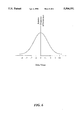
- FIG. 6 illustrates the predictive coding frequency used by the encoding portion of the system of FIG. 1.
- the present invention provides a system for transferring image data from one computer to another without requiring a powerful CPU and large amounts of memory. Storage capacity and cost considerations make it impossible for devices such as printers to store every conceivable font type. Even with many stored font types, the printer must still have the flexibility to use new character fonts that may be desired.
- the system of the present invention processes raster data to greatly reduce the size of the raster data. This permits the flexibility of embedding new character fonts within the text data even in low-cost systems that do not have a powerful CPU and large amounts of memory. While prior art systems may embed a raster font, such as outline fonts, these systems require large amounts of memory to support even a single such font.
- a outline font set typically requires approximately 60 kilobytes (Kbytes) of code used to process the font set and 40 Kbytes to 100 Kbytes for the outline of the font set.
- Kbytes kilobytes
- the transmission of a single outline font set may require as much as 160 Kbytes of memory.
- a typical printed page may contain several fonts such as Times-Roman, Times-Roman Bold, and Times-Roman Italics, each of which is considered a separate font that must be individually defined.
- the use of multiple fonts significantly increase the memory requirement.
- the system of present invention greatly reduces the size of the raster data for each font set to approximately 3 Kbytes to 15 Kbytes for each font set at a fixed resolution of 300 dots per inch (DPI).
- DPI dots per inch
- the reduced memory requirements makes it practical to embed a font set within a facsimile message.
- the dramatically reduced size of embedded font data also means that the transmission time of text data with an embedded font set is reduced. Reduced transmission time results in more efficient transfer of data and, in the case of some computers such as a facsimile machine, lower transmission costs.
- the system also provides flexibility in communication between devices such as those described above. The ability to incorporate the present invention into many devices gives greater interoperability than achievable with the prior art.
- Bit-map data is considered to be a very low level data form.
- the receiving computer whether it is a printer or a FAX machine, can use embedded character fonts without the sophisticated data processing required by some prior art systems, such as PostScriptTM, in which data is transferred in a high level format that requires a great deal of data processing.
- PostScriptTM some prior art systems, such as PostScriptTM, in which data is transferred in a high level format that requires a great deal of data processing.
- the present invention permits the use of less sophisticated microprocessors in the receiving computer which further reduces costs.
- the image data processed by the present invention is a raster image, which is comprised of a sequence of horizontal scan rows. Each horizontal scan row is, in turn, made up of a series of pixels. Each pixel in the raster image is represented by one or more data bits. In its simplest form, there is a single data bit for each pixel indicating whether the pixel is "colored” or not. As can be appreciated, the term “colored” refers to whether the pixel is visible on the particular display medium.
- a simple display medium has a "background color", which indicates the data value of pixels that are invisible on the particular display medium.
- a “foreground color” refers to pixels that have a different data value than the data value for a background color and are thus visible on the particular display medium.
- a typical printer such as a laser printer has one data bit for each pixel to indicate whether or not the pixel is colored.
- the pixels have a first data value (i.e., first logic state) if they have the foreground color, such as black, and have a second data value (i.e., a second opposite logic state) if they have the background color, such as white.
- a video display terminal may have pixels that have the first logic state for a white foreground color and the second logic state for a black background color.
- the same logic state may result in a different physical display depending on the particular display medium.
- the actual data values of the pixels depend on the particular display medium.
- a typical printer such as a laser printer, has one data bit for each pixel to indicate whether or not the pixel is colored.
- the pixels have a first logic state if they are colored (i.e., visible in the image) and have a second, opposite logic state if they are not colored (i.e., invisible in the image).
- an 81/2 inch by 11 inch page will have 2550 pixels in each horizontal scan row.
- the values for the locations of pixels in each horizontal scan row therefore will range from 0 to 2549.
- the term "horizontal scan rows" is used with reference to typical devices that scan each row of pixels in a horizontal direction. The present invention is equally applicable to devices that scan in the vertical direction.
- the present invention is embodied in a system 10 shown in the functional block diagram of FIG. 1.
- the system 10 comprises a central processing unit (CPU) 12 and a memory 14, which may include both random access memory (RAM) and read-only memory (ROM).
- the data storage area 16 may be a temporary buffer that receives a portion of the image data and processes the image data in real-time as a stream of data.
- a scan engine 18 may be used to scan printed pages for transmission. The data from the scan engine 18 is provided to the data storage area 16, which acts as a temporary buffer to hold the image data while the system 10 processes the data stream in real-time.
- a printer 20 is used by the system 10 to print received image data.
- the printer 20 may be an integral part of the system 10 if the system is a FAX machine or a copier. Alternatively, the printer 20 may be a stand alone device.
- a conventional change vector generator 22 sequentially analyzes each horizontal scan row to determine the location at which the pixels in the horizontal scan row change from the first logic state to the second logic state, and from the second logic state to the first logic state.
- the locations of the changes in logic state are relative to a first end of the horizontal scan row and thus may be viewed as vectors having an origin at the beginning of each horizontal scan row, a horizontal direction, and a length being indicated by the relative position of each pixel that changes logic states with respect to the logic state of the prior pixel in the horizontal scan row.
- the change vector generator 22 stores the change vectors for each of the horizontal scan rows in a change vector table 24.
- the change vector table 24 need not contain the change vectors for all horizontal scan rows in an image.
- the change vector table 24 may contain only the change vectors for one horizontal scan row at a time.
- a chaingon generator 26 analyzes the data in the change vector table 24 and creates one or more chaingons to represent the raster image data.
- Chaingons are defined as a series of pixels having the same logic state that are adjacent in the horizontal direction, the vertical direction, or diagonally. The creation of chaingons will be discussed in detail below. In the presently preferred embodiment, chaingons are defined as visible pixels that are adjacent in the horizontal direction, the vertical direction, or diagonally.
- the chaingons are stored within a chaingon table 28, which may be part of the memory 14.
- a chaingon encoder 30 analyzes each chaingon separately and encodes the chaingon.
- the encoded chaingons may then be compressed and stored in a compressed data storage area 32, which may be part of the memory 14.
- the various components of the system 10 described above are interconnected by a bus 34 which may carry timing signals, and power as well as data signals.
- step 50 the change vector generator 22 (see FIG. 1) establishes an initial value for the logic state of the horizontal scan row being analyzed. In the present invention, starting at a first end of the horizontal scan row, such as the left end if the system 10 is analyzing the horizontal scan row from left to right, each horizontal scan row is assumed to start with a white pixel (i.e., an invisible pixel).
- step 54 the change vector generator 22 initializes a pointer for the horizontal scan row to point to this first pixel.
- the change vector generator 22 determines whether the logic state of the pixel indicated by the pointer is different from the logic state of the previous pixel in the horizontal scan row. If there is a change in logic state from the previous pixel, the result of decision 56 is YES. In that event, the change vector generator 22 stores the current value of the pointer in the change vector table 24 (see FIG. 1) in step 58. It should be noted that each value in the change vector table 24 is a change vector for the particular horizontal scan row. If there was not a change in the logic state from the previous pixel, the result of decision 56 is NO.
- the change vector generator 22 in decision 60 determines whether the current value of the pointer corresponds to the second end of the horizontal scan row. If the current value of the pointer does not correspond to the second end of the horizontal scan row, the result of decision 60 is NO. In that event, the change vector generator 22 increments current value of the pointer for the horizontal scan row in step 62, and returns to decision 56 to continue the analysis of the horizontal scan row. If the current value of the pointer does correspond to the second end of the horizontal scan row, the result of decision 60 is YES, and the change vector generator 22 ends the analysis for the horizontal scan row in step 64.
- FIG. 3 An example of the operation of the change vector generator 22 is illustrated in FIG. 3 where a portion 70 of a raster image is shown.
- the raster image is stored as a bit map data file in the data storage area 16 (see FIG. 1).
- the portion 70 comprises seven horizontal scan rows 72a through 72g.
- the change vector generator 22 sequentially scans the pixels in each of the horizontal scan rows 72a through 72g and determines the change vectors for each horizontal scan row in the manner described in the flowchart of FIG. 2.
- the first horizontal scan row 72a contains a change at pixel 0 (assuming a white initial pixel). Therefore, the first change vector for the first horizontal scan row 72a terminates at pixel 0, and the second change vector terminates at pixel 1 (the location where the pixel changes from black to white).
- change vectors terminate at pixels 3 and 6.
- the change vectors are processed in pairs by the system 10.
- Each pair of change vectors indicates a series of pixels on a horizontal scan row that have the same logic state.
- Each series of pixels defined by a change vector pair may be thought of as a run of pixels.
- the very first change vector on a horizontal scan row indicates the location where a run of black pixels begins.
- the second change vector indicates the location on the horizontal scan row where a run of white pixels begins.
- the first change vector of a change vector pair is considered to be inclusive while the second change vector of the change vector pair is considered to be exclusive.
- the first change vector of the change vector pair indicates a pixel location where a run of black pixels begins, while the second change vector of the change vector pair indicates the location after the last pixel in the particular run of black pixels.
- a run of pixels may be as short as one pixel or as long as the entire horizontal scan row. It should be realized that the same type of processing could be performed by defining a black initial pixel and using white pixels as the first change vector of a change vector pair.
- the change vector pairs for the horizontal scan rows 72a through 72g of FIG. 3 are shown below in Table 1.
- the change vector generator 22 stores the change vector pairs in the change vector table 24.
- the change vector table 24 need not contain the change vectors for all horizontal scan rows to begin the process of generating chaingons.
- the chaingon generator 26 sequentially analyzes the change vector pairs for each horizontal scan row and places the visible pixels into one or more chaingons.
- the system 10 will generate one or more chaingons for the entire raster image by analyzing the change vectors for the raster image one horizontal scan row at a time.
- chaingons are defined as visible pixels that are adjacent in the horizontal direction, the vertical direction, or diagonally.
- the pixels 3 to 5 in the horizontal scan row 72a are adjacent in the horizontal direction. Therefore, the chaingon generator 26 will assign them to one chaingon.
- the pixels 5 to 6 in the horizontal scan row 72b are adjacent to each other in the horizontal direction and are also adjacent to the pixels 3 to 5 in the horizontal scan row 72a.
- the pixels 5 to 6 in the horizontal scan row 72b will be added to the chaingon that includes the pixels 3 to 5 in the horizontal scan row 72a.
- the pixels 5 to 6 in the horizontal scan row 72c are adjacent to each other in the horizontal direction and are also adjacent to the pixels 5 to 6 in the horizontal scan row 72b. Therefore, the pixels 5 to 6 in the horizontal scan row 72c will be added to the chaingon that includes the pixels 5 to 6 in the horizontal scan row 72b and the pixels 3 to 5 in the horizontal scan row 72a.
- the open chaingon will continue to grow in this manner until the chaingon generator finds a horizontal scan row that has no addition pixels that are adjacent to the open chaingon in either the vertical or diagonal direction.
- the horizontal scan row 72f contains no pixels that overlap the pixels 5 to 6 in the horizontal scan row 72e in either the vertical or diagonal directions. Therefore, the chaingon generator will close the open chaingon. It should be noted that other chaingons may continue to remain open so long as there are new pixels to add to the chaingon in each horizontal scan row. It should also be noted that not all contiguous pixels are in the same chaingon. As will be discussed below, where a particular pixel could fall into more than one chaingon, an arbitrary rule is used to assign the pixel to one chaingon.
- Change vectors are used to efficiently determine the location of runs of black pixels on the horizontal scan rows and to define the chaingons.
- the chaingon generator 26 could analyze the bit-map data file itself to determine the locations at which the pixels change logic states.
- the chaingon generator 26 creates or opens a chaingon for each of the change vector pairs on the first horizontal scan row that contains change vectors because each of the change vector pairs in the horizontal scan row indicate separate runs of black pixels that are not adjacent in the horizontal direction.
- the chaingons opened by the chaingon generator 26 will remain open so long as each subsequent horizontal scan row contains change vectors that overlap are adjacent to a change vector in the previous horizontal scan row either vertically or diagonally.
- the flowchart of FIG. 4, taken in conjunction with Table 1 above, may be used to illustrate the process of generating chaingons.
- the chaingon generator 26 (see FIG. 1) starts at step 80 with all change vectors having been previously generated in accordance with the flowchart of FIG. 2.
- the chaingon generator 26 starts a chaingon list for each of the change vector pairs in the first horizontal scan row that contains change vectors.
- the first horizontal scan row 72a has the following change vector pairs: (0,1),(3,6).
- the two change vector pairs indicate that there are two runs of black pixels in the horizontal scan row 72a.
- the first run of black pixels starts at pixel 0 and ends at pixel 1 thus indicating a run of only one black pixel.
- the second run of black pixels starting at pixel 3 and ending at pixel 6, thus indicating a run of three black pixels.
- the chaingon generator 26 will open two chaingons.
- the first chaingon contains pixel 0, and the second chaingon contains pixels 3, 4, and 5.
- the chaingon generator 26 will create a chaingon list containing the change vector pairs associated with each of the chaingons.
- the chaingon lists, which contain change vector pairs, are stored within the chaingon table 28.
- step 84 the chaingon generator 26 moves to the next horizontal scan row.
- decision 86 the chaingon generator 26 determines whether a pair of change vectors in the horizontal scan row currently being analyzed overlaps any change vector pairs from the horizontal scan row just previously analyzed.
- overlap refers to a change vector pair whose corresponding pixels are adjacent to the pixels in any open chaingon in either the vertical or diagonal direction. The overlap can be determined mathematically by comparing the change vector pairs for the horizontal scan row currently being analyzed to the change vector pair or pairs from the previously analyzed horizontal scan row to determine if there is overlap.
- the pixels 5 and 6 of the horizontal scan row 72b overlap the pixels 3 to 5 of the horizontal scan row 72a in the vertical direction (i.e., the pixel 5 of the horizontal scan row 72b is vertically adjacent to the pixel 5 of the horizontal scan row 72a). Therefore, the change vector pair (5,7) in the horizontal scan row 72b will be added to the open chaingon containing the change vector pair (3,6) in the horizontal scan row 72a.
- the horizontal scan row 72b has the following change vector pairs: (1, 4), (5, 7). These change vector pairs indicate a first run of black pixels starting at pixel 1 and ending at pixel 4, and a second run of black pixels starting at pixel 5 and ending at pixel 7.
- the chaingon generator 26 compares the change vector pairs for the horizontal scan row 72b with the open chaingons to determine if there is any overlap.
- the first run of black pixels, indicated by the change vector pair (0,1) in the horizontal scan row 72a corresponds to the first open chaingon.
- the first run of black pixels, indicated by the change vector pair, (1,4), in the horizontal scan row 72b is adjacent to the change vector pair, (0,1), in the horizontal scan row 72a in a diagonal direction.
- the result of decision 86 is YES.
- the first run of black pixels in the horizontal scan row 72b is also adjacent to the second chaingon in a vertical direction because the pixel 3 in the horizontal scan row 72b is under the pixel 3 in the horizontal scan row 72a, which is part of the second chaingon.
- the change vector pair corresponding to the first run of black pixels in the horizontal scan row 72b could be placed in either the first or second chaingons.
- the chaingon generator 26 arbitrarily assigns the pixels to the earliest opened of those chaingons. Therefore, in step 88, the first change vector pair, corresponding to the first run of black pixels in the horizontal scan row 72b, is placed in the chaingon list for the first chaingon.
- the first change vector pair, corresponding to the first run of black pixels in the horizontal scan row 72b could be placed in the chaingon list for the second chaingon.
- the chaingon generator 26 determines if there are any additional change vector pairs remaining on the horizontal scan row currently being analyzed. If there are remaining change vector pairs on the horizontal scan row, the result of decision 90 is YES, and in step 92 the chaingon generator moves to the next change vector pair for the horizontal scan row currently being analyzed at step 92 and returns to decision 86.
- the result of decision 90 is YES, and in step 92 the chaingon generator moves to the next change vector pair for the horizontal scan row currently being analyzed at step 92 and returns to decision 86.
- the chaingon generator 22 will return to decision 86 and determine that the second pair of change vectors belong in the second chaingon.
- the chaingon generator will place the second pair of change vectors in the second chaingon list. The chaingon generator repeats this process for each of the change vector pairs for the horizontal scan row 72b.
- the chaingon generator 26 moves to decision 96 to determine if the horizontal scan row currently being analyzed is the last horizontal scan row in the data file. If there are more horizontal scan rows to be analyzed, the result of decision 96 is NO, and the chaingon generator 26 returns to step 84 to analyze the next horizontal scan row 72c with respect to the horizontal scan row just analyzed.
- the change vector generator 22 and the chaingon generator 26 analyze the horizontal scan rows from top to bottom. Each horizontal scan row is analyzed from left to right.
- bit-map data file starting at the top or bottom and analyzing from left to right or right to left. For example, it may be more efficient to encode from top to bottom instead of left to right if the bit-map data file contains characters that are in a landscape mode. Alternatively, it may also be more efficient to generate one or more chaingons to encode the background pixels rather than the foreground pixels.
- the present invention is intended to encompass chaingon generation of any logic state in any direction in the bit-map data file.
- step 94 the chaingon generator 26 starts new chaingon list for the change vector pair in the current horizontal scan row. Any chaingon list that does not have a new change vector pair added for the current horizontal scan row is closed or retired. This means that the particular chaingon list will not get any larger, and the particular chaingon is now completely defined by the change vector pairs in the chaingon list. For example, it can be seen that the horizontal scan row 72f has only one change vector pair: (1, 3). When the chaingon generator 26 analyzes the horizontal scan row 72f, it determines that there is no change vector pair that overlaps the second chaingon in the horizontal scan row 72e.
- the chaingon list for the second chaingon contains change vector pairs for the horizontal scan rows 72a through 72e. Similarly, there are no change vector pairs in the horizontal scan row 72g that overlap the first chaingon in the horizontal scan row 72f. Therefore, the first chaingon is closed when the chaingon generator analyzes the horizontal scan row 72g.
- the chaingon list for the first chaingon contains change vector pairs for the horizontal scan rows 72a through 72f.
- the chaingon generator 26 continues the sequential analysis of each remaining horizontal scan row until all horizontal scan rows have been analyzed and change vector pairs have been assigned to a chaingon list. If there are no more horizontal scan rows to be analyzed, the result of decision 96 is YES, and the chaingon generator 26 closes any open chaingons and ends the process of generating chaingons in step 98. In the example of FIG. 3, the third chaingon is closed because there are no more pixels that can overlap in subsequent horizontal scan rows.
- the chaingon lists are stored in the chaingon table 28 (see FIG. 1).
- the chaingon table created for the pixels of FIG. 3 is set forth in Table 2 below.
- the system 10 formats the chaingon lists in a manner that permits the easy encoding of each chaingon.
- Each formatted chaingon list includes a header containing information related to the position of the upper left corner of the chaingon in the raster image data file and the length of the chaingon (in number of horizontal scan rows), followed by the data for each horizontal scan row within the chaingon.
- Table 3 the formatted chaingon lists are represented in Table 3 below.
- the X and Y Offsets in the header for the first chaingon indicates that the chaingon starts at the first pixel of the first horizontal scan row.
- the X and Y Offsets in the headers for the second and third chaingons indicate that they start at the fourth pixel of the first horizontal scan row, and at the fifth pixel of the seventh horizontal scan row, respectively.
- the Y Extent in the header for the first chaingon indicates that the chaingon is six horizontal scan rows in length
- the Y Extent in the headers for the second and third chaingons indicate that they have lengths of five and one horizontal scan rows, respectively. In this manner, the entire raster image data file is placed into a series of one or more chaingons.
- the system 10 encodes each chaingon independently using delta encoding on each chaingon.
- Delta encoding is a well known form of data encoding that will be described only briefly herein. It is not necessary for the system 10 to have all chaingons completely defined before the delta encoding can begin.
- the second chaingon in FIG. 3 is closed during the analysis of horizontal scan row 72f.
- the chaingon encoder 30 (see FIG. 1) can begin encoding the second chaingon while the chaingon generator 26 is still analyzing the entries in change vector table 24 for horizontal scan row 72g.
- the chaingon encoder 30 encodes each chaingon by encoding the chaingon data associated with each horizontal scan row of the chaingon relative to the chaingon data in the previous horizontal scan row.
- the chaingon data in each horizontal scan row is encoded as a delta or offset value relative to the chaingon data from the previous horizontal scan row.
- the first chaingon in FIG. 3 is shown alone in FIG. 5 to better illustrate the encoding process.
- Table 3 indicates that the first chaingon starts at the first pixel of the first horizontal scan row and is six horizontal scan rows in length.
- the first change vector pair in the data portion of the formatted first chaingon list of Table 3 following the header is the change vector pair (0,1).
- the next change vector pair, (1,4) for the first chaingon is encoded relative to the previous entry.
- the delta values for the next change vector pair, (1,4), for the first chaingon are (+1, +3), indicating that the run of black pixels in the next horizontal scan row starts one pixel to the right of the previous starting location and ends three pixels to the right of the previous ending location.
- These delta values may be easily determined by subtracting the previous chaingon data from the current chaingon data.
- the original chaingon change vector pairs and the delta values for the first chaingon are shown in Table 4 below.
- delta encoding can reduce the size of the data values because every delta value is merely an offset from the previous data value.
- the delta values are generally small because chaingons, by definition, are closely related pixels within the bit-map data file. Each delta value is represented by several data bits. Because most delta values tend to be small, it makes the encoding process more predictable. As illustrated in greater detail below, this permits the delta encoding to use a smaller number of data bits for the most common offset values and a larger number of data bits for larger, less common, offset values.
- This type of statistical encoding is well known in the art. For example, Modified Huffman coding, which is commonly used in facsimile data encoding, relies on statistics to select a small number of data bits for more common data patterns, and a larger number of data bits for less common data patterns.
- the curve shown in FIG. 6 illustrates the statistical nature of the delta encoding process for chaingons.
- a zero offset value is very common and occurs with the greatest frequency.
- the offset values of +1 and -1 are the next most common. Other offset values occur with less frequency.
- the system 10 uses two data bits to represent the three most common offset values.
- the data bits 00 represent a zero offset value.
- the data bits 01 represent a +1 offset value, while the data bits 11 represent a -1 offset value.
- Less common offset values are represented with more data bits.
- the data bits 1011 represent a +2 offset value while the data bits 1010 represent a -2 offset value.
- the data bits 1001 represent a +3 offset value. More data bits are required to represent less common offset values.
- the encoded data generated by the chaingon encoder 30 require no delimiter to identify the end of one code and the start of a new code.
- the data bits in each of the codes are unique and the system 10 recognizes the end of a particular code by the pattern of data bits in the code. This encoding shares the well known prefix property of Huffman codes. For example, the first data bits 00 in the example above represents a 0 offset value. There are no other data bit patterns that begin with the data bits 00. Thus, the system 10 recognizes the data bits 00 as a complete code. Similarly, the data bits 01 represent a +1 offset value. There are no other data bit patterns that begin with the data bits 01. Thus, each code is uniquely identified by the pattern of data bits.
- the delta encoded data bits representing the offset values may be further compressed prior to transmission to the receiving computer.
- the system 10 uses LZ data compression, which further compresses the delta encoded data bits.
- LZ data compression is well known in the art and will not be described herein.
- a number of other well known data compression techniques such as run length encoding (RLE) or Huffman encoding can be used.
- RLE run length encoding
- Huffman encoding Huffman encoding
- the present invention is not limited by the specific order in which the compression techniques are applied.
- the system 10 could perform Huffman encoding followed by LZ data compression.
- the system 10 could first use LZ data compression followed by Huffman encoding.
- the compressed data for the chaingons is stored in the compressed data storage area 32 (see FIG. 1), which may be part of the memory 14.
- the compressed data in the compressed data storage area 32 may be embedded within the text data or facsimile message, as previously discussed, and transmitted along with the data or message.
- the compressed data may be efficiently decompressed by reversing the compression process applied to the data. Because compression and decompression of data is well known in the art, it will not be described herein.
- the chaingon data can be decoded by reversing the process described above.
- the data bit patterns for the first chaingon indicate the offset values from the start of the chaingon.
- the X and Y offsets and the Y extent indicate the location and number of horizontal scan lines for the first chaingon. With this information, the decoding process may be easily performed.
- each chaingon can be successively decompressed into a single buffer, combining with previous chaingons with a logical OR operation. Filling a run of pixels is fast, particularly for repeated runs that fit within a machine word size (e.g., 32 bits).
- the chaingon representation permits raster image data, such as a character font set, to be represented in a dramatically smaller amount of space than a typical character font set.
- the data in Table 5 below indicates the amount of data storage required by typical character font sets using conventional techniques, the same character font sets processed by the system 10 into chaingons, and the chaingons that have been further compressed using LZ data compression.
Landscapes
- Engineering & Computer Science (AREA)
- Multimedia (AREA)
- Physics & Mathematics (AREA)
- General Physics & Mathematics (AREA)
- Theoretical Computer Science (AREA)
- Compression Of Band Width Or Redundancy In Fax (AREA)
- Image Processing (AREA)
- Compression, Expansion, Code Conversion, And Decoders (AREA)
Priority Applications (5)
| Application Number | Priority Date | Filing Date | Title |
|---|---|---|---|
| US08/232,624 US5504591A (en) | 1994-04-25 | 1994-04-25 | System and method for compressing graphic images |
| DE69531080T DE69531080T2 (de) | 1994-04-25 | 1995-04-24 | System und Verfahren zur Bildkompression |
| JP09834495A JP4101312B2 (ja) | 1994-04-25 | 1995-04-24 | グラフィック画像の圧縮システムおよび方法 |
| EP95106135A EP0680016B1 (en) | 1994-04-25 | 1995-04-24 | System and method for compressing images |
| JP2007075395A JP4366408B2 (ja) | 1994-04-25 | 2007-03-22 | グラフィック画像の圧縮システムおよび方法 |
Applications Claiming Priority (1)
| Application Number | Priority Date | Filing Date | Title |
|---|---|---|---|
| US08/232,624 US5504591A (en) | 1994-04-25 | 1994-04-25 | System and method for compressing graphic images |
Publications (1)
| Publication Number | Publication Date |
|---|---|
| US5504591A true US5504591A (en) | 1996-04-02 |
Family
ID=22873883
Family Applications (1)
| Application Number | Title | Priority Date | Filing Date |
|---|---|---|---|
| US08/232,624 Expired - Lifetime US5504591A (en) | 1994-04-25 | 1994-04-25 | System and method for compressing graphic images |
Country Status (4)
| Country | Link |
|---|---|
| US (1) | US5504591A (ja) |
| EP (1) | EP0680016B1 (ja) |
| JP (2) | JP4101312B2 (ja) |
| DE (1) | DE69531080T2 (ja) |
Cited By (38)
| Publication number | Priority date | Publication date | Assignee | Title |
|---|---|---|---|---|
| US5754164A (en) * | 1994-06-29 | 1998-05-19 | Fujitsu Limited | Outline font expanding method and outline font expanding device |
| US5848246A (en) | 1996-07-01 | 1998-12-08 | Sun Microsystems, Inc. | Object-oriented system, method and article of manufacture for a client-server session manager in an interprise computing framework system |
| US5867612A (en) * | 1996-03-27 | 1999-02-02 | Xerox Corporation | Method and apparatus for the fast scaling of an image |
| US5889893A (en) * | 1996-03-27 | 1999-03-30 | Xerox Corporation | Method and apparatus for the fast rotation of an image |
| US5915098A (en) * | 1997-10-24 | 1999-06-22 | Digital Equipment Corp. | System for compressing bit maps to be shared and displayed in collaborative tool by client and server systems |
| US5987245A (en) | 1996-07-01 | 1999-11-16 | Sun Microsystems, Inc. | Object-oriented system, method and article of manufacture (#12) for a client-server state machine framework |
| US5999972A (en) | 1996-07-01 | 1999-12-07 | Sun Microsystems, Inc. | System, method and article of manufacture for a distributed computer system framework |
| US6038590A (en) | 1996-07-01 | 2000-03-14 | Sun Microsystems, Inc. | Object-oriented system, method and article of manufacture for a client-server state machine in an interprise computing framework system |
| US6226400B1 (en) * | 1998-06-24 | 2001-05-01 | Colorcom, Ltd. | Defining color borders in a raster image by identifying and breaking contrast ties |
| US6266709B1 (en) | 1996-07-01 | 2001-07-24 | Sun Microsystems, Inc. | Object-oriented system, method and article of manufacture for a client-server failure reporting process |
| US6272555B1 (en) | 1996-07-01 | 2001-08-07 | Sun Microsystems, Inc. | Object-oriented system, method and article of manufacture for a client-server-centric interprise computing framework system |
| US6304893B1 (en) | 1996-07-01 | 2001-10-16 | Sun Microsystems, Inc. | Object-oriented system, method and article of manufacture for a client-server event driven message framework in an interprise computing framework system |
| US6424991B1 (en) | 1996-07-01 | 2002-07-23 | Sun Microsystems, Inc. | Object-oriented system, method and article of manufacture for a client-server communication framework |
| US6434598B1 (en) | 1996-07-01 | 2002-08-13 | Sun Microsystems, Inc. | Object-oriented system, method and article of manufacture for a client-server graphical user interface (#9) framework in an interprise computing framework system |
| US6546360B1 (en) * | 1998-10-30 | 2003-04-08 | Trimble Navigation Limited | Device servicing system and method |
| US20050015249A1 (en) * | 2002-09-04 | 2005-01-20 | Microsoft Corporation | Entropy coding by adapting coding between level and run-length/level modes |
| US20050052294A1 (en) * | 2003-09-07 | 2005-03-10 | Microsoft Corporation | Multi-layer run level encoding and decoding |
| US20050068208A1 (en) * | 2003-09-07 | 2005-03-31 | Microsoft Corporation | Scan patterns for progressive video content |
| US20050078754A1 (en) * | 2003-09-07 | 2005-04-14 | Microsoft Corporation | Scan patterns for interlaced video content |
| US20050254706A1 (en) * | 2004-05-13 | 2005-11-17 | Bailey James R | Method of an image processor for transforming a n-bit data packet to a m-bit data packet using a lookup table |
| US7016547B1 (en) | 2002-06-28 | 2006-03-21 | Microsoft Corporation | Adaptive entropy encoding/decoding for screen capture content |
| US20060202818A1 (en) * | 2005-03-09 | 2006-09-14 | Greenberg Stephen J | Pet tracking systems, other tracking systems, and portable virtual fence |
| US20070016418A1 (en) * | 2005-07-15 | 2007-01-18 | Microsoft Corporation | Selectively using multiple entropy models in adaptive coding and decoding |
| US20070016415A1 (en) * | 2005-07-15 | 2007-01-18 | Microsoft Corporation | Prediction of spectral coefficients in waveform coding and decoding |
| US20070036224A1 (en) * | 2005-08-12 | 2007-02-15 | Microsoft Corporation | Prediction of transform coefficients for image compression |
| US20070036223A1 (en) * | 2005-08-12 | 2007-02-15 | Microsoft Corporation | Efficient coding and decoding of transform blocks |
| US20070036443A1 (en) * | 2005-08-12 | 2007-02-15 | Microsoft Corporation | Adaptive coding and decoding of wide-range coefficients |
| US20070268314A1 (en) * | 2006-05-17 | 2007-11-22 | Kabushiki Kaisha Toshiba | Graphic data retrieving apparatus, method, and program |
| US20080198933A1 (en) * | 2007-02-21 | 2008-08-21 | Microsoft Corporation | Adaptive truncation of transform coefficient data in a transform-based ditigal media codec |
| US20080228476A1 (en) * | 2002-09-04 | 2008-09-18 | Microsoft Corporation | Entropy coding by adapting coding between level and run length/level modes |
| US20080312758A1 (en) * | 2007-06-15 | 2008-12-18 | Microsoft Corporation | Coding of sparse digital media spectral data |
| US20090273706A1 (en) * | 2008-05-02 | 2009-11-05 | Microsoft Corporation | Multi-level representation of reordered transform coefficients |
| US7693709B2 (en) | 2005-07-15 | 2010-04-06 | Microsoft Corporation | Reordering coefficients for waveform coding or decoding |
| CN102841933A (zh) * | 2012-08-06 | 2012-12-26 | 北京地拓科技发展有限公司 | 栅格数据写入的方法及装置,栅格数据读取的方法及装置 |
| CN102902712A (zh) * | 2012-08-13 | 2013-01-30 | 北京地拓科技发展有限公司 | 栅格因子数据写入的方法及装置、读取的方法及装置 |
| US8406307B2 (en) | 2008-08-22 | 2013-03-26 | Microsoft Corporation | Entropy coding/decoding of hierarchically organized data |
| US8848261B1 (en) * | 2012-02-15 | 2014-09-30 | Marvell International Ltd. | Method and apparatus for using data compression techniques to increase a speed at which documents are scanned through a scanning device |
| CN110264533A (zh) * | 2019-06-25 | 2019-09-20 | 北京慧眼智行科技有限公司 | 一种数据传输方法、装置及电子设备 |
Families Citing this family (4)
| Publication number | Priority date | Publication date | Assignee | Title |
|---|---|---|---|---|
| GB0031605D0 (en) * | 2000-12-27 | 2001-02-07 | Koninkl Philips Electronics Nv | Graphic image coding |
| US8286334B2 (en) | 2006-07-14 | 2012-10-16 | Hitachi Global Storage Technologies, Netherlands B.V. | Method of manufacturing pre-sliders for read write heads by annealing to saturation |
| JP2011022784A (ja) * | 2009-07-15 | 2011-02-03 | Sony Corp | 情報処理装置、ブロック検出方法およびプログラム |
| US8213117B2 (en) | 2010-06-04 | 2012-07-03 | Tdk Corporation | Magnetic head with protective layer and a protective film removal method for the magnetic head |
Citations (10)
| Publication number | Priority date | Publication date | Assignee | Title |
|---|---|---|---|---|
| US4053930A (en) * | 1972-12-31 | 1977-10-11 | Ricoh Co., Ltd. | Method and device for coding compressing video information |
| US4097903A (en) * | 1975-10-30 | 1978-06-27 | Kokusai Denshin Denwa Kabushiki Kaisha | Facsimile signal coding system |
| US4470073A (en) * | 1978-09-07 | 1984-09-04 | Hitachi, Ltd. | Facsimile transmitter |
| US4539587A (en) * | 1983-12-30 | 1985-09-03 | Gte Products Corporation | Shift register driven video measurement system for microcomputer |
| US4701803A (en) * | 1984-06-05 | 1987-10-20 | Canon Kabushiki Kaisha | Image data compression apparatus |
| US4783828A (en) * | 1986-06-02 | 1988-11-08 | Honeywell Inc. | Two-dimensional object recognition using chain codes, histogram normalization and trellis algorithm |
| US4982293A (en) * | 1988-06-02 | 1991-01-01 | Ricoh Company, Ltd. | Method of compressing halftone image data |
| US5067023A (en) * | 1989-06-29 | 1991-11-19 | Samsung Electronics Co., Ltd. | Image data coding apparatus |
| US5305111A (en) * | 1990-12-11 | 1994-04-19 | Industrial Technology Research Institute | Run length encoding method and system |
| US5414526A (en) * | 1993-10-21 | 1995-05-09 | Microsoft Corp. | System and method for encoding facsimile data |
Family Cites Families (6)
| Publication number | Priority date | Publication date | Assignee | Title |
|---|---|---|---|---|
| JPS5132488B2 (ja) * | 1971-12-30 | 1976-09-13 | ||
| JPS6055475A (ja) * | 1983-09-06 | 1985-03-30 | Matsushita Electric Ind Co Ltd | 境界線抽出装置 |
| JPH01243188A (ja) * | 1988-03-24 | 1989-09-27 | Meidensha Corp | 輪郭検出装置 |
| JPH01277976A (ja) * | 1988-04-28 | 1989-11-08 | Meidensha Corp | 画像処理装置 |
| GB2245394A (en) * | 1990-06-18 | 1992-01-02 | Rank Cintel Ltd | Video framestore selective addressing system |
| DE69332918D1 (de) * | 1992-01-24 | 2003-06-05 | Canon Kk | Gerät und Verfahren zum Extrahieren von Kantendaten und zur Kodierung von Bilddaten mit diesen Kantendaten |
-
1994
- 1994-04-25 US US08/232,624 patent/US5504591A/en not_active Expired - Lifetime
-
1995
- 1995-04-24 JP JP09834495A patent/JP4101312B2/ja not_active Expired - Lifetime
- 1995-04-24 DE DE69531080T patent/DE69531080T2/de not_active Expired - Lifetime
- 1995-04-24 EP EP95106135A patent/EP0680016B1/en not_active Expired - Lifetime
-
2007
- 2007-03-22 JP JP2007075395A patent/JP4366408B2/ja not_active Expired - Lifetime
Patent Citations (10)
| Publication number | Priority date | Publication date | Assignee | Title |
|---|---|---|---|---|
| US4053930A (en) * | 1972-12-31 | 1977-10-11 | Ricoh Co., Ltd. | Method and device for coding compressing video information |
| US4097903A (en) * | 1975-10-30 | 1978-06-27 | Kokusai Denshin Denwa Kabushiki Kaisha | Facsimile signal coding system |
| US4470073A (en) * | 1978-09-07 | 1984-09-04 | Hitachi, Ltd. | Facsimile transmitter |
| US4539587A (en) * | 1983-12-30 | 1985-09-03 | Gte Products Corporation | Shift register driven video measurement system for microcomputer |
| US4701803A (en) * | 1984-06-05 | 1987-10-20 | Canon Kabushiki Kaisha | Image data compression apparatus |
| US4783828A (en) * | 1986-06-02 | 1988-11-08 | Honeywell Inc. | Two-dimensional object recognition using chain codes, histogram normalization and trellis algorithm |
| US4982293A (en) * | 1988-06-02 | 1991-01-01 | Ricoh Company, Ltd. | Method of compressing halftone image data |
| US5067023A (en) * | 1989-06-29 | 1991-11-19 | Samsung Electronics Co., Ltd. | Image data coding apparatus |
| US5305111A (en) * | 1990-12-11 | 1994-04-19 | Industrial Technology Research Institute | Run length encoding method and system |
| US5414526A (en) * | 1993-10-21 | 1995-05-09 | Microsoft Corp. | System and method for encoding facsimile data |
Cited By (68)
| Publication number | Priority date | Publication date | Assignee | Title |
|---|---|---|---|---|
| US5754164A (en) * | 1994-06-29 | 1998-05-19 | Fujitsu Limited | Outline font expanding method and outline font expanding device |
| US5889893A (en) * | 1996-03-27 | 1999-03-30 | Xerox Corporation | Method and apparatus for the fast rotation of an image |
| US5867612A (en) * | 1996-03-27 | 1999-02-02 | Xerox Corporation | Method and apparatus for the fast scaling of an image |
| US5999972A (en) | 1996-07-01 | 1999-12-07 | Sun Microsystems, Inc. | System, method and article of manufacture for a distributed computer system framework |
| US5987245A (en) | 1996-07-01 | 1999-11-16 | Sun Microsystems, Inc. | Object-oriented system, method and article of manufacture (#12) for a client-server state machine framework |
| US5848246A (en) | 1996-07-01 | 1998-12-08 | Sun Microsystems, Inc. | Object-oriented system, method and article of manufacture for a client-server session manager in an interprise computing framework system |
| US6038590A (en) | 1996-07-01 | 2000-03-14 | Sun Microsystems, Inc. | Object-oriented system, method and article of manufacture for a client-server state machine in an interprise computing framework system |
| US6266709B1 (en) | 1996-07-01 | 2001-07-24 | Sun Microsystems, Inc. | Object-oriented system, method and article of manufacture for a client-server failure reporting process |
| US6272555B1 (en) | 1996-07-01 | 2001-08-07 | Sun Microsystems, Inc. | Object-oriented system, method and article of manufacture for a client-server-centric interprise computing framework system |
| US6304893B1 (en) | 1996-07-01 | 2001-10-16 | Sun Microsystems, Inc. | Object-oriented system, method and article of manufacture for a client-server event driven message framework in an interprise computing framework system |
| US6424991B1 (en) | 1996-07-01 | 2002-07-23 | Sun Microsystems, Inc. | Object-oriented system, method and article of manufacture for a client-server communication framework |
| US6434598B1 (en) | 1996-07-01 | 2002-08-13 | Sun Microsystems, Inc. | Object-oriented system, method and article of manufacture for a client-server graphical user interface (#9) framework in an interprise computing framework system |
| US5915098A (en) * | 1997-10-24 | 1999-06-22 | Digital Equipment Corp. | System for compressing bit maps to be shared and displayed in collaborative tool by client and server systems |
| US6226400B1 (en) * | 1998-06-24 | 2001-05-01 | Colorcom, Ltd. | Defining color borders in a raster image by identifying and breaking contrast ties |
| US6546360B1 (en) * | 1998-10-30 | 2003-04-08 | Trimble Navigation Limited | Device servicing system and method |
| US7016547B1 (en) | 2002-06-28 | 2006-03-21 | Microsoft Corporation | Adaptive entropy encoding/decoding for screen capture content |
| US20070116370A1 (en) * | 2002-06-28 | 2007-05-24 | Microsoft Corporation | Adaptive entropy encoding/decoding for screen capture content |
| US7218790B2 (en) | 2002-06-28 | 2007-05-15 | Microsoft Corporation | Adaptive entropy encoding/decoding for screen capture content |
| US7340103B2 (en) | 2002-06-28 | 2008-03-04 | Microsoft Corporation | Adaptive entropy encoding/decoding for screen capture content |
| US20060104530A1 (en) * | 2002-06-28 | 2006-05-18 | Microsoft Corporation | Adaptive entropy encoding/decoding for screen capture content |
| US8712783B2 (en) | 2002-09-04 | 2014-04-29 | Microsoft Corporation | Entropy encoding and decoding using direct level and run-length/level context-adaptive arithmetic coding/decoding modes |
| US20110035225A1 (en) * | 2002-09-04 | 2011-02-10 | Microsoft Corporation | Entropy coding using escape codes to switch between plural code tables |
| US8090574B2 (en) | 2002-09-04 | 2012-01-03 | Microsoft Corporation | Entropy encoding and decoding using direct level and run-length/level context-adaptive arithmetic coding/decoding modes |
| US7840403B2 (en) | 2002-09-04 | 2010-11-23 | Microsoft Corporation | Entropy coding using escape codes to switch between plural code tables |
| US7822601B2 (en) | 2002-09-04 | 2010-10-26 | Microsoft Corporation | Adaptive vector Huffman coding and decoding based on a sum of values of audio data symbols |
| US7433824B2 (en) | 2002-09-04 | 2008-10-07 | Microsoft Corporation | Entropy coding by adapting coding between level and run-length/level modes |
| US20080228476A1 (en) * | 2002-09-04 | 2008-09-18 | Microsoft Corporation | Entropy coding by adapting coding between level and run length/level modes |
| US20050015249A1 (en) * | 2002-09-04 | 2005-01-20 | Microsoft Corporation | Entropy coding by adapting coding between level and run-length/level modes |
| US9390720B2 (en) | 2002-09-04 | 2016-07-12 | Microsoft Technology Licensing, Llc | Entropy encoding and decoding using direct level and run-length/level context-adaptive arithmetic coding/decoding modes |
| US20050053151A1 (en) * | 2003-09-07 | 2005-03-10 | Microsoft Corporation | Escape mode code resizing for fields and slices |
| US7469011B2 (en) | 2003-09-07 | 2008-12-23 | Microsoft Corporation | Escape mode code resizing for fields and slices |
| US20050052294A1 (en) * | 2003-09-07 | 2005-03-10 | Microsoft Corporation | Multi-layer run level encoding and decoding |
| US20050068208A1 (en) * | 2003-09-07 | 2005-03-31 | Microsoft Corporation | Scan patterns for progressive video content |
| US7688894B2 (en) | 2003-09-07 | 2010-03-30 | Microsoft Corporation | Scan patterns for interlaced video content |
| US20050078754A1 (en) * | 2003-09-07 | 2005-04-14 | Microsoft Corporation | Scan patterns for interlaced video content |
| US7782954B2 (en) | 2003-09-07 | 2010-08-24 | Microsoft Corporation | Scan patterns for progressive video content |
| US7724827B2 (en) | 2003-09-07 | 2010-05-25 | Microsoft Corporation | Multi-layer run level encoding and decoding |
| US7580564B2 (en) | 2004-05-13 | 2009-08-25 | Lexmark International, Inc. | Method of an image processor for transforming a n-bit data packet to a m-bit data packet using a lookup table |
| US20050254706A1 (en) * | 2004-05-13 | 2005-11-17 | Bailey James R | Method of an image processor for transforming a n-bit data packet to a m-bit data packet using a lookup table |
| US20060202818A1 (en) * | 2005-03-09 | 2006-09-14 | Greenberg Stephen J | Pet tracking systems, other tracking systems, and portable virtual fence |
| US7411492B2 (en) | 2005-03-09 | 2008-08-12 | Stephen Jay Greenberg | Pet tracking systems, other tracking systems, and portable virtual fence |
| US20070016415A1 (en) * | 2005-07-15 | 2007-01-18 | Microsoft Corporation | Prediction of spectral coefficients in waveform coding and decoding |
| US20070016418A1 (en) * | 2005-07-15 | 2007-01-18 | Microsoft Corporation | Selectively using multiple entropy models in adaptive coding and decoding |
| US7599840B2 (en) | 2005-07-15 | 2009-10-06 | Microsoft Corporation | Selectively using multiple entropy models in adaptive coding and decoding |
| US7684981B2 (en) | 2005-07-15 | 2010-03-23 | Microsoft Corporation | Prediction of spectral coefficients in waveform coding and decoding |
| US7693709B2 (en) | 2005-07-15 | 2010-04-06 | Microsoft Corporation | Reordering coefficients for waveform coding or decoding |
| US7565018B2 (en) | 2005-08-12 | 2009-07-21 | Microsoft Corporation | Adaptive coding and decoding of wide-range coefficients |
| US8599925B2 (en) | 2005-08-12 | 2013-12-03 | Microsoft Corporation | Efficient coding and decoding of transform blocks |
| US20070036223A1 (en) * | 2005-08-12 | 2007-02-15 | Microsoft Corporation | Efficient coding and decoding of transform blocks |
| US20070036443A1 (en) * | 2005-08-12 | 2007-02-15 | Microsoft Corporation | Adaptive coding and decoding of wide-range coefficients |
| US7933337B2 (en) | 2005-08-12 | 2011-04-26 | Microsoft Corporation | Prediction of transform coefficients for image compression |
| US20070036224A1 (en) * | 2005-08-12 | 2007-02-15 | Microsoft Corporation | Prediction of transform coefficients for image compression |
| US20070268314A1 (en) * | 2006-05-17 | 2007-11-22 | Kabushiki Kaisha Toshiba | Graphic data retrieving apparatus, method, and program |
| US20080198933A1 (en) * | 2007-02-21 | 2008-08-21 | Microsoft Corporation | Adaptive truncation of transform coefficient data in a transform-based ditigal media codec |
| US8184710B2 (en) | 2007-02-21 | 2012-05-22 | Microsoft Corporation | Adaptive truncation of transform coefficient data in a transform-based digital media codec |
| US20080312758A1 (en) * | 2007-06-15 | 2008-12-18 | Microsoft Corporation | Coding of sparse digital media spectral data |
| US7774205B2 (en) | 2007-06-15 | 2010-08-10 | Microsoft Corporation | Coding of sparse digital media spectral data |
| US8179974B2 (en) | 2008-05-02 | 2012-05-15 | Microsoft Corporation | Multi-level representation of reordered transform coefficients |
| US9172965B2 (en) | 2008-05-02 | 2015-10-27 | Microsoft Technology Licensing, Llc | Multi-level representation of reordered transform coefficients |
| US20090273706A1 (en) * | 2008-05-02 | 2009-11-05 | Microsoft Corporation | Multi-level representation of reordered transform coefficients |
| US8406307B2 (en) | 2008-08-22 | 2013-03-26 | Microsoft Corporation | Entropy coding/decoding of hierarchically organized data |
| US9013760B1 (en) | 2012-02-15 | 2015-04-21 | Marvell International Ltd. | Method and apparatus for using data compression techniques to increase a speed at which documents are scanned through a scanning device |
| US8848261B1 (en) * | 2012-02-15 | 2014-09-30 | Marvell International Ltd. | Method and apparatus for using data compression techniques to increase a speed at which documents are scanned through a scanning device |
| CN102841933B (zh) * | 2012-08-06 | 2015-01-14 | 北京地拓科技发展有限公司 | 栅格数据写入的方法及装置,栅格数据读取的方法及装置 |
| CN102841933A (zh) * | 2012-08-06 | 2012-12-26 | 北京地拓科技发展有限公司 | 栅格数据写入的方法及装置,栅格数据读取的方法及装置 |
| CN102902712B (zh) * | 2012-08-13 | 2015-08-12 | 北京地拓科技发展有限公司 | 栅格因子数据写入的方法及装置、读取的方法及装置 |
| CN102902712A (zh) * | 2012-08-13 | 2013-01-30 | 北京地拓科技发展有限公司 | 栅格因子数据写入的方法及装置、读取的方法及装置 |
| CN110264533A (zh) * | 2019-06-25 | 2019-09-20 | 北京慧眼智行科技有限公司 | 一种数据传输方法、装置及电子设备 |
Also Published As
| Publication number | Publication date |
|---|---|
| JP4101312B2 (ja) | 2008-06-18 |
| EP0680016B1 (en) | 2003-06-18 |
| EP0680016A3 (en) | 1996-02-28 |
| EP0680016A2 (en) | 1995-11-02 |
| DE69531080T2 (de) | 2003-12-04 |
| JPH0863606A (ja) | 1996-03-08 |
| DE69531080D1 (de) | 2003-07-24 |
| JP4366408B2 (ja) | 2009-11-18 |
| JP2007184978A (ja) | 2007-07-19 |
Similar Documents
| Publication | Publication Date | Title |
|---|---|---|
| US5504591A (en) | System and method for compressing graphic images | |
| US6731814B2 (en) | Method for compressing digital documents with control of image quality and compression rate | |
| EP2481206B1 (en) | Image processing apparatus and processing method therefor | |
| JP3400944B2 (ja) | 併合データ要素を生成する方法およびその印刷データ処理パイプライン | |
| JP3063957B2 (ja) | 画像処理装置 | |
| EP0809192A2 (en) | Method and apparatus for rendering fontless structured documents | |
| US6219454B1 (en) | Image processing apparatus | |
| US6343157B1 (en) | Image coding system, image decoding system, image processing system, image coding method, image decoding method, and image processing method | |
| JPH1051642A (ja) | 画像処理装置 | |
| JP3461309B2 (ja) | ハフマン符号化データ圧縮装置 | |
| JP2830690B2 (ja) | 画像処理装置 | |
| US8014622B2 (en) | Image processing apparatus and method for attribute data encoding | |
| US5406282A (en) | Data coding and decoding with improved efficiency | |
| EP0902398B1 (en) | Method and system for compressing and decompressing binary representations of dithered images | |
| US6721456B1 (en) | Color image data and control bit compression scheme with run length encoding | |
| US6934417B2 (en) | Transcoding scheme for assistance in image transformations | |
| US8494261B2 (en) | Image processing apparatus, image processing method, and computer-readable medium | |
| JPH09167222A (ja) | 画像処理装置 | |
| JPH06113145A (ja) | 画像処理装置 | |
| JPH118771A (ja) | 画像出力装置および画像出力方法およびコンピュータが読み出し可能なプログラムを格納した記憶媒体 | |
| JP2000227848A (ja) | 画像処理装置 | |
| JP2683506B2 (ja) | データ圧縮方法及び装置、データ伸長方法及び装置 | |
| JP3323555B2 (ja) | 画像処理装置およびその方法 | |
| JP2001078042A (ja) | 画像伸長処理装置および画像圧縮処理装置 | |
| Duttweiler | Bilevel image coding |
Legal Events
| Date | Code | Title | Description |
|---|---|---|---|
| AS | Assignment |
Owner name: MICROSOFT CORPORATION, WASHINGTON Free format text: ASSIGNMENT OF ASSIGNORS INTEREST;ASSIGNOR:DUJARI, RAJEEV;REEL/FRAME:006981/0408 Effective date: 19940424 |
|
| STCF | Information on status: patent grant |
Free format text: PATENTED CASE |
|
| FEPP | Fee payment procedure |
Free format text: PAYOR NUMBER ASSIGNED (ORIGINAL EVENT CODE: ASPN); ENTITY STATUS OF PATENT OWNER: LARGE ENTITY |
|
| FPAY | Fee payment |
Year of fee payment: 4 |
|
| FEPP | Fee payment procedure |
Free format text: PAYOR NUMBER ASSIGNED (ORIGINAL EVENT CODE: ASPN); ENTITY STATUS OF PATENT OWNER: LARGE ENTITY Free format text: PAYER NUMBER DE-ASSIGNED (ORIGINAL EVENT CODE: RMPN); ENTITY STATUS OF PATENT OWNER: LARGE ENTITY |
|
| FPAY | Fee payment |
Year of fee payment: 8 |
|
| FPAY | Fee payment |
Year of fee payment: 12 |
|
| AS | Assignment |
Owner name: MICROSOFT TECHNOLOGY LICENSING, LLC, WASHINGTON Free format text: ASSIGNMENT OF ASSIGNORS INTEREST;ASSIGNOR:MICROSOFT CORPORATION;REEL/FRAME:034541/0001 Effective date: 20141014 |