US5533596A - Hydraulic, adjustable vibration damper for motor vehicles - Google Patents
Hydraulic, adjustable vibration damper for motor vehicles Download PDFInfo
- Publication number
- US5533596A US5533596A US08/374,923 US37492395A US5533596A US 5533596 A US5533596 A US 5533596A US 37492395 A US37492395 A US 37492395A US 5533596 A US5533596 A US 5533596A
- Authority
- US
- United States
- Prior art keywords
- displaceable member
- fluid
- damping
- orifice
- chamber
- Prior art date
- Legal status (The legal status is an assumption and is not a legal conclusion. Google has not performed a legal analysis and makes no representation as to the accuracy of the status listed.)
- Expired - Fee Related
Links
- 239000012530 fluid Substances 0.000 claims abstract description 121
- 238000013016 damping Methods 0.000 claims abstract description 109
- 238000004891 communication Methods 0.000 claims description 15
- 238000007789 sealing Methods 0.000 claims description 10
- 239000007788 liquid Substances 0.000 claims description 7
- 239000000725 suspension Substances 0.000 claims description 7
- 230000001276 controlling effect Effects 0.000 claims description 5
- 230000001681 protective effect Effects 0.000 claims description 3
- 230000001105 regulatory effect Effects 0.000 claims description 2
- 230000002093 peripheral effect Effects 0.000 claims 4
- 230000003247 decreasing effect Effects 0.000 claims 2
- 230000000750 progressive effect Effects 0.000 description 3
- 230000002349 favourable effect Effects 0.000 description 2
- 238000012986 modification Methods 0.000 description 2
- 230000004048 modification Effects 0.000 description 2
- 239000006096 absorbing agent Substances 0.000 description 1
- 238000010276 construction Methods 0.000 description 1
- 230000006837 decompression Effects 0.000 description 1
- 230000000994 depressogenic effect Effects 0.000 description 1
- 238000003780 insertion Methods 0.000 description 1
- 230000037431 insertion Effects 0.000 description 1
- 239000002184 metal Substances 0.000 description 1
- 238000000034 method Methods 0.000 description 1
- 238000005086 pumping Methods 0.000 description 1
- 230000035939 shock Effects 0.000 description 1
Images




Classifications
-
- F—MECHANICAL ENGINEERING; LIGHTING; HEATING; WEAPONS; BLASTING
- F16—ENGINEERING ELEMENTS AND UNITS; GENERAL MEASURES FOR PRODUCING AND MAINTAINING EFFECTIVE FUNCTIONING OF MACHINES OR INSTALLATIONS; THERMAL INSULATION IN GENERAL
- F16F—SPRINGS; SHOCK-ABSORBERS; MEANS FOR DAMPING VIBRATION
- F16F9/00—Springs, vibration-dampers, shock-absorbers, or similarly-constructed movement-dampers using a fluid or the equivalent as damping medium
- F16F9/32—Details
- F16F9/44—Means on or in the damper for manual or non-automatic adjustment; such means combined with temperature correction
- F16F9/46—Means on or in the damper for manual or non-automatic adjustment; such means combined with temperature correction allowing control from a distance, i.e. location of means for control input being remote from site of valves, e.g. on damper external wall
- F16F9/461—Means on or in the damper for manual or non-automatic adjustment; such means combined with temperature correction allowing control from a distance, i.e. location of means for control input being remote from site of valves, e.g. on damper external wall characterised by actuation means
-
- F—MECHANICAL ENGINEERING; LIGHTING; HEATING; WEAPONS; BLASTING
- F16—ENGINEERING ELEMENTS AND UNITS; GENERAL MEASURES FOR PRODUCING AND MAINTAINING EFFECTIVE FUNCTIONING OF MACHINES OR INSTALLATIONS; THERMAL INSULATION IN GENERAL
- F16F—SPRINGS; SHOCK-ABSORBERS; MEANS FOR DAMPING VIBRATION
- F16F2230/00—Purpose; Design features
- F16F2230/18—Control arrangements
- F16F2230/183—Control arrangements fluid actuated
Definitions
- This invention generally relates to a hydraulic, adjustable vibration damper for motor vehicles.
- a vibration damper can have a damping piston fastened to a piston rod, which damping piston divides the work cylinder into two chambers that are filled with damping fluid.
- damping valves in the damping piston, and a fluid bypass can be located parallel to the valves of the damping piston.
- a fluid bypass can be located parallel to the valves of the damping piston.
- In the bypass there can be at least one valve which reacts, or operates, as a function of the pressure.
- To control the bypass there can be a device to adjust a control body of the valve, which device can be pressurized in the closing direction of the control body by means of a pressure medium. Between the pressure medium and the control body, there can be an axially movable pressure intensifier which can be sealed about the circumference thereof.
- vibration damper in which a control body pressurizes a bypass with the interposition of a pressure intensifier, is disclosed by Federal Republic of Germany Patent No. 41 20 122, which has correspondence to U.S. Pat. No. 5,207,300.
- the pressure intensifier is pressurized by an externally applied control pressure, e.g. hydraulically or pneumatically.
- a higher damping is added to a base damping, so that as a result of the high damping, the roll stability of a vehicle, or the starting conditions of a truck, can be improved, and if the control pressure drops or disappears, as a result of the internal system pressure in the decompression stage of the vibration damper, the control body can be brought into the open position and can be held there automatically.
- the damping force characteristic of such a vibration damper can thereby be switched so that it is either progressive or degressive. A variation of the damping force characteristic, for example, more progressive or more degressive characteristics, cannot be achieved with such a device.
- the object of the present invention is therefore to create a hydraulic, adjustable vibration damper in which the control body of a bypass is pressurized, with the interposition of a pressure intensifier, by a hydraulic or pneumatic adjustment device, and whereby the damping can be modified in terms of its damping force characteristic and level to adjust to the current conditions both progressively and degressively.
- the present invention teaches that this object can be accomplished by means of a valve unit which includes a biasing device that provides a force which acts in the direction opposite to the force of the pressure intensifier, and to the pressure medium acting on the intensifier.
- Such an apparatus can essentially make it advantageously possible to use different control pressures to preferably achieve a change in the cross section of the bypass, and thereby essentially achieve a damping force adjustment which is a function of the opposing biasing force of the biasing device.
- a continuous damping force can essentially be achieved with a simultaneous modification of the characteristic, e.g. progressively or degressively.
- control body and the pressure intensifier, along with at least one biasing member, or spring can be part of a bracing system.
- the spring can preferably be a spring plate.
- the spring can preferably pressurize the pressure intensifier, and/or the spring can preferably be coupled to the control body.
- the additional spring force can either pressurize the pressure intensifier directly, or the additional spring force can be part of a bracing chain, whereby the spring acts on the control body and the control body acts on the pressure intensifier, each in the direction opposite to the external control pressure.
- the spring can preferably control the flow cross section of the bypass by means of the control body, and a constant passage can also be advantageously provided in the spring.
- invention includes “inventions”, that is, the plural of "invention”.
- invention applicant does not in any way admit that the present application does not include more than one patentably and non-obviously distinct invention, and maintains the possibility that this application may include more than one patentably and non-obviously distinct invention.
- the Applicant hereby asserts that the disclosure of this application may include more than one invention, and, in the event that there is more than one invention, that these inventions may be patentable and non-obvious, one with respect to the other.
- an adjustable vibration damper for damping vibrations of a suspension of a motor vehicle, the damper comprising: a cylinder; damping fluid disposed within the cylinder; a piston rod projecting into the cylinder, the piston rod being movable axially within the cylinder; a damping piston disposed on the piston rod, the damping piston dividing the cylinder into a first chamber and a second chamber; apparatus for providing fluid communication between the first chamber and the second chamber; valve apparatus for regulating flow of damping fluid through the apparatus for providing fluid communication, the valve apparatus comprising: displaceable member apparatus, the displaceable member apparatus being movable in a first direction from a first substantially open position to a second substantially closed position to at least substantially close the apparatus for providing fluid communication and the displaceable member apparatus being movable from the second substantially closed position to the first substantially open position in a second direction to at least substantially open the apparatus for providing fluid communication; apparatus for applying a first force to the displaceable member apparatus to move the displaceable member apparatus in
- an adjustable vibration damper system for damping vibrations of a suspension of a motor vehicle, the damper system comprising a vibration damper and a apparatus for adjusting a damping characteristic of the vibration damper, the vibration damper comprising: a first cylinder, the first cylinder having a first end and a second end; damping fluid disposed within the cylinder; a piston rod projecting into the cylinder through the first end of the cylinder, the piston rod being movable axially within the cylinder; a damping piston disposed on the piston rod, the damping piston dividing the cylinder into a first chamber and a second chamber; the damping piston comprising passage apparatus for providing fluid communication between the first chamber and the second chamber; the passage apparatus comprising first valve apparatus for damping flow of damping fluid through the passage apparatus; a fluid bypass disposed in parallel to the passage apparatus and connecting the first chamber and the second chamber, the bypass apparatus for bypassing flow of damping fluid about the damping piston upon movement of the piston rod into and out of the first
- FIGS. 1 and 1a show a vibration damper in partial cross section, with a damping valve attached to the side of the damper;
- FIG. 2 shows a vibration damper in cross section with a damping valve integrated into the piston within the damper
- FIG. 2a shows a vibration damper similar to that of FIG. 2, but with additional components
- FIGS. 3 and 3a are details of an embodiment of a damping valve located in the piston.
- FIGS. 4 and 5 illustrate additional embodiments of a damping valve with different configurations of the biasing member.
- FIGS. 1 and 1a One type of vibration damper 20 in accordance with the present invention is illustrated in FIGS. 1 and 1a.
- a vibration damper can have an inner, or work cylinder 11, which defines a work chamber 21 therein.
- a piston rod 9 can preferably extend into the work chamber 21, and a damping piston 10 can preferably be disposed on the piston rod 9.
- the damping piston 10 can essentially divide the work chamber 21, within cylinder 11, into an upper chamber portion 21a and a lower chamber portion 21b.
- the damping piston 10 can preferably be equipped with valves 10a and 10b to generate a damping force by damping fluid flow between the two chambers 21a and 21b.
- the upper end of the work cylinder 11 can preferably be sealed by means of a piston rod guiding and sealing unit 22.
- FIG. 1 is essentially a two-tube vibration damper, and as such, has a second, or container tube 23 disposed about the work cylinder 11.
- This second tube 23 essentially defines a fluid reservoir 24 between the work cylinder 11 and the container tube 23.
- the reservoir 24 can also preferably have a volume compensation space 25 adjacent the upper end thereof.
- the upper chamber 21a can also preferably be in fluid communication with the lower chamber 21b by means of a bypass 12 and by means of a damping valve 13.
- the bypass 12 can preferably be disposed in parallel to the valves 10a, 10b.
- the bypass 12 can preferably be formed by still another tube 26 disposed about the work cylinder 11.
- This bypass 12 can preferably be in fluid communication with the upper chamber 21a via at least one orifice 27 in the work cylinder 11.
- the bypass 12 can preferably be opened and closed by means of the damping valve unit 13, 13a.
- the damping valve unit 13, 13a is preferably disposed externally on the outer tube 23. Additional details of this type of damping valve unit 13 are shown in FIG. 4.
- the damper 20 can preferably have fastening portions 30 and 31.
- the damper 20 could also be provided with a protective sleeve 32 about its upper portion thereof to protect the piston rod 9 when the piston rod 9 is withdrawn out of the damper 20, and to hinder access of dirt to the vicinity of the seal unit 22.
- FIGS. 2 and 2a illustrate one possible variation of a vibration damper 20 as set forth hereabove.
- the components of the vibration damper 20, with the exception of the valve unit 13b, 13c and bypass 12, would preferably be the same as depicted in FIG. 1, and therefore a further depiction of the vibration damper components is not provided in FIGS. 2 and 2a.
- FIGS. 2 and 2a essentially only show the piston unit 10 in greater detail.
- the damping valve unit 13b, 13c, which regulates the bypass 12, and the bypass 12, parallel to the damping valves 10a and 10b in the damping piston 10, are preferably located inside the damping piston 10, instead of externally to the working chamber 11 as shown in FIG. 1. Additional details of a damping valve 13d, 13g which can be utilized within the piston 10 are illustrated in FIGS. 3 and 5.
- FIG. 2a illustrates in more detail the valves 10a and 10b, and as shown, such valves 10a and 10b can preferably be one-way valves.
- the piston 10 can preferably have a sealing body 35 for sealing against the inside of the work cylinder 11.
- This sealing body 35 can preferably have at least two passages 36 and 37 therethrough connecting the chambers 21a and 21b (see FIG. 1).
- the passage 36 can preferably have one end thereof open to the chamber 21b, while the passage 37 can have an end open to the chamber 21a.
- the other end of passage 36 can preferably be closed by a flexible plate 38, which flexible plate 38 can preferably be opened by fluid flowing in the direction of arrow 40, caused by an insertion of the piston 10 into the damper 20.
- the other end of passage 37 can preferably be closed by a flexible plate 39, which flexible plate 39 can preferably be opened by fluid flowing in the direction of arrow 41, caused by a withdrawal of the piston from the damper 20.
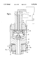
- FIGS. 3 and 3a show details of the portion of the damping piston 10 which contains the damping valve 13d, 13e for the control of the bypass 12.
- the bypass 12 can essentially be opened or closed by the control body 2.
- a biasing member, such as the spring 1 can preferably be coupled to the control body 2 to form a control edge. Simultaneously, there can always be a small volume of fluid which can flow through the constant passage 8.
- a pressure can preferably be applied to the control body 2 by an external pressure 14.
- the external pressure 14 can preferably be applied in conjunction with a pressure intensifier 4 and an additional spring 5.
- Such pressure intensifiers are generally known (as shown in the earlier mentioned U.S. Pat. No. 5,207,300), and are therefore not described in greater detail herein.
- the springs 1 and 5 can preferably be formed by metal discs, or cones, which are flexible in a direction at least substantially perpendicular to a major plane thereof.
- FIG. 2a shows one type of possible configuration of a pressure source 34 for applying the fluid pressure 14.
- a pressure source can essentially be a pump device for pumping air or liquid into the valve unit 13c.
- a control unit 34a for controlling operation of the pressure source 34.
- Such a control unit can preferably be automatically actuated, but a user-actuated device could also be provided.
- FIG. 1a depicts one type of pressure source 34 and the connection thereof to a tube-mounted valve unit 13a.
- a channel 16 can preferably be provided to allow any medium in the space 15 to escape from the space 15 during movement of the pressure intensifier 4 towards the passage 12, and also allow medium to reenter the space 15 upon release of the pressure 14 and movement of the pressure intensifier 4 away from the passage 12.
- This channel 16 can essentially be configured to feed into an additional passage 16a in the piston rod 9, to vent the space 15 directly into the atmosphere.
- the fluid in the space 15 be a liquid, in which case, a reservoir 16b (shown in outline in FIG. 2a) could be provided for containing the liquid.
- the control body 2 can preferably be pressurized at an appropriate first pressure 14 by means of the pressure intensifier 4, to move the control body 2 into engagement with the spring 1.
- the control body 2, in conjunction with the spring 1 can close the bypass 12 with respect to the recess 17 at a first amount of pressure 14, and only the constant passage 8 can remain open, as depicted in FIG. 3.
- the spring 1 can be curved downwardly in the plane of the drawing, as shown in FIG. 3a, so that the flow cross section 6 between the spring 1 and the recess 3 can also be closed. In this position, the constant passage 8 would also be closed.
- the control body 2 When the external pressure 14 is reduced, and at the corresponding system pressure via the bypass 12, i.e., a damping fluid pressure in the bypass 12, the control body 2 can preferably be moved essentially continuously with respect to the spring 1, so that the corresponding desired damping characteristic can be achieved.
- the damping force can be adjusted by means of the control pressure, changing the characteristic from degressive, through linear, to progressive. Even at extremely low piston velocities, a high adjustment capability (spread) becomes possible.
- FIG. 4 illustrates an additional embodiment, with the difference that this damping valve unit 13f can preferably be attached laterally to a vibration damper as illustrated in FIG. 1.
- a damping valve could be a separate unit, separate from the vibration damper, and fluidly connected to the vibration damper by hoses.
- the pressure 14 can also be applied externally to the pressure intensifier 4, by some sort of pressure source as shown in FIG. 2a.
- the cavity 15 can be vented directly into the atmosphere via the channel 16. Otherwise, this damping valve 13f corresponds in principle to the damping valve described above with reference to FIG. 3.
- FIG. 5 illustrates an additional embodiment, in which the control body 2b is again pressurized by the pressure intensifier 4, and here again the external pressure 14, together with an additional spring 5, acts on the pressure intensifier 4.
- a spring 1a which acts in the direction opposite to the pressure medium 14, can alternatively be located in the cavity 15.
- the spring 1a can preferably be supported, on one hand, against the base 18 and, on the other hand, against the pressure intensifier 4. Since the spring 1a is no longer disposed adjacent the passage 12, the passage 8 can also be eliminated from the spring 1a.
- the function is essentially the same as that of the damping valve 13d illustrated in FIG. 3.
- the spring 1, 1a could be formed by other types of biasing devices, for example, a coil spring, an elastomeric member, etc.
- One feature of the invention resides broadly in the hydraulic, adjustable vibration damper for motor vehicles, with a damping piston fastened to a piston rod, which damping piston divides the work cylinder into two chamber halves filled with damping fluid, whereby in a bypass located parallel to the valves of the damping piston there is at least one valve which reacts as a function of the pressure, and to control the bypass, there is a device to adjust [See Translator's Note 1 on last page] a control body which can be pressurized in the closing direction by means of a pressure medium, whereby between the pressure medium and the control body there is an axially movable pressure intensifier which is sealed on the circumference, characterized by the fact that corresponding to the pressure intensifier 4 there is a spring force 1 which acts in the opposite direction to the pressure medium.
- Another feature of the invention resides broadly in the vibration damper characterized by the fact that the control body 2 and the pressure intensifier 4, with at least one spring 1 are in a bracing chain (are part of a bracing system?).
- Yet another feature of the invention resides broadly in the vibration damper characterized by the fact that the spring 1 is a spring plate.
- Still another feature of the invention resides broadly in the vibration damper characterized by the fact that the spring 1 pressurizes the pressure intensifier 4.
- a further feature of the invention resides broadly in the vibration damper characterized by the fact that the spring 1 is coupled to the control body 2.
- Another feature of the invention resides broadly in the vibration damper characterized by the fact that the spring 1 controls the flow cross section 6 of the bypass by means of the control body 2.
- Yet another feature of the invention resides broadly in the vibration damper characterized by the fact that the spring 1 has a constant passage.
Landscapes
- Engineering & Computer Science (AREA)
- General Engineering & Computer Science (AREA)
- Mechanical Engineering (AREA)
- Fluid-Damping Devices (AREA)
- Vehicle Body Suspensions (AREA)
Applications Claiming Priority (2)
| Application Number | Priority Date | Filing Date | Title |
|---|---|---|---|
| DE4401393.0 | 1994-01-19 | ||
| DE4401393A DE4401393C1 (de) | 1994-01-19 | 1994-01-19 | Hydraulischer, verstellbarer Schwingungsdämpfer für Kraftfahrzeuge |
Publications (1)
| Publication Number | Publication Date |
|---|---|
| US5533596A true US5533596A (en) | 1996-07-09 |
Family
ID=6508204
Family Applications (1)
| Application Number | Title | Priority Date | Filing Date |
|---|---|---|---|
| US08/374,923 Expired - Fee Related US5533596A (en) | 1994-01-19 | 1995-01-18 | Hydraulic, adjustable vibration damper for motor vehicles |
Country Status (5)
| Country | Link |
|---|---|
| US (1) | US5533596A (ja) |
| JP (1) | JPH07208533A (ja) |
| DE (1) | DE4401393C1 (ja) |
| FR (1) | FR2715203B1 (ja) |
| IT (1) | IT1271270B (ja) |
Cited By (21)
| Publication number | Priority date | Publication date | Assignee | Title |
|---|---|---|---|---|
| US5988332A (en) * | 1997-07-23 | 1999-11-23 | Marzocchi S.P.A. | Hydraulic shock absorber |
| US6112868A (en) * | 1994-10-31 | 2000-09-05 | Gabriel Ride Control Products, Inc. | Externally adjustable dampening control for a shock absorber |
| US6286640B1 (en) * | 1995-12-13 | 2001-09-11 | Etablissements Jean Perret | Longitudinal axis shock absorber with bypass channel |
| US6450304B1 (en) * | 2001-02-12 | 2002-09-17 | Delphi Technologies, Inc. | Piston and rod assembly for air-actuated variable damping |
| US20040020730A1 (en) * | 2002-05-29 | 2004-02-05 | Progressive Suspension, Inc., | Hydraulic dampers with pressure regulated control valve |
| US6837344B2 (en) | 2001-02-12 | 2005-01-04 | Delphi Technologies, Inc. | Piston and rod assembly for air-actuated variable damping |
| US20050133978A1 (en) * | 2003-12-17 | 2005-06-23 | Luc Lemmens | Air pressure proportional damper |
| US20050173214A1 (en) * | 2004-02-10 | 2005-08-11 | Luc Lemmens | Air pressure proportional damper for shock absorber |
| US20050178626A1 (en) * | 2004-02-13 | 2005-08-18 | Progressive Suspension, Inc. | Pressure regulating dampers |
| US20070085247A1 (en) * | 2005-10-10 | 2007-04-19 | Zf Friedrichshafen Ag | Self-pumping hydropneumatic spring strut with internal level control |
| US7374028B2 (en) | 2003-07-08 | 2008-05-20 | Fox Factory, Inc. | Damper with pressure-sensitive compression damping |
| US20080168897A1 (en) * | 2007-01-12 | 2008-07-17 | Suzie Guay | Actuator with a protective sleeve for a piston |
| US20080314708A1 (en) * | 2007-06-21 | 2008-12-25 | Zf Friedrichshafen Ag | Piston-cylinder unit |
| US20100300821A1 (en) * | 2009-05-29 | 2010-12-02 | Shunsuke Mori | Volume compensation accumulator apparatus and suspension system using the same |
| US20100326267A1 (en) * | 2009-06-30 | 2010-12-30 | Hata Hideki | Hydraulic cylinder |
| US20130340606A1 (en) * | 2008-05-28 | 2013-12-26 | Frank Born | Continuously blockable locking device |
| US20130340607A1 (en) * | 2008-05-28 | 2013-12-26 | Frank Born | Continuously blockable locking device |
| US8950558B2 (en) | 2011-12-29 | 2015-02-10 | Fox Factory, Inc. | Dampers with thermal expansion compensation |
| US10900539B2 (en) | 2005-12-30 | 2021-01-26 | Fox Factory, Inc. | Fluid damper having a damping profile favorable for absorbing the full range of compression forces, including low- and high-speed compression forces |
| CN114658786A (zh) * | 2022-03-22 | 2022-06-24 | 常州纺织服装职业技术学院 | 核电站用大型液压阻尼器 |
| US20240003401A1 (en) * | 2020-11-23 | 2024-01-04 | Vb-Techniek B.V. | Hydraulic shock absorber |
Families Citing this family (8)
| Publication number | Priority date | Publication date | Assignee | Title |
|---|---|---|---|---|
| WO1994016706A1 (en) | 1993-01-28 | 1994-08-04 | Neorx Corporation | Therapeutic inhibitors of vascular smooth muscle cells |
| JPH09287631A (ja) * | 1996-04-19 | 1997-11-04 | Yamaha Motor Co Ltd | 減衰器 |
| DE19901639B4 (de) | 1998-02-14 | 2009-04-02 | Zf Sachs Ag | Druckabhängig reagierendes Ventil, insbesondere für einen Schwingungsdämpfer |
| SE520522C2 (sv) | 1999-07-27 | 2003-07-22 | Zf Sachs Ag | Tryckberoende reagerande ventil, särskilt för en svängningsdämpare |
| DE102004013921A1 (de) | 2004-03-22 | 2005-10-13 | Siemens Ag | Vorrichtung zum Antrieb einer plattenförmigen Antriebsmasse, insbesondere zum Antrieb eines Streustrahlenrasters eines Röngtendiagnostikgeräts |
| JP2011094691A (ja) * | 2009-10-29 | 2011-05-12 | Hitachi Automotive Systems Ltd | 緩衝器 |
| JP5690179B2 (ja) * | 2011-03-18 | 2015-03-25 | カヤバ工業株式会社 | 緩衝装置 |
| CN107630964B (zh) * | 2017-09-20 | 2023-08-11 | 肇庆市维德亚科技有限公司 | 一种液压阻尼器 |
Citations (3)
| Publication number | Priority date | Publication date | Assignee | Title |
|---|---|---|---|---|
| US4850461A (en) * | 1987-07-22 | 1989-07-25 | Robert Bosch Gmbh | Shock absorber having a throttle with a variable cross section |
| DE4120122A1 (de) * | 1990-06-29 | 1992-01-09 | Boge Ag | Hydraulischer, verstellbarer schwingungsdaempfer fuer kraftfahrzeuge |
| US5207300A (en) * | 1990-06-29 | 1993-05-04 | Boge Aktiengesellschaft | Hydraulic, adjustable vibration damper for motor vehicles |
Family Cites Families (2)
| Publication number | Priority date | Publication date | Assignee | Title |
|---|---|---|---|---|
| DE3619402A1 (de) * | 1986-06-09 | 1987-12-17 | Boge Ag | Verstellbarer, hydraulischer stossdaempfer |
| DE4105771A1 (de) * | 1991-02-23 | 1992-08-27 | Boge Ag | Hydraulischer, verstellbarer schwingungsdaempfer fuer kraftfahrzeuge |
-
1994
- 1994-01-19 DE DE4401393A patent/DE4401393C1/de not_active Expired - Fee Related
- 1994-12-15 IT ITMI942518A patent/IT1271270B/it active IP Right Grant
-
1995
- 1995-01-18 US US08/374,923 patent/US5533596A/en not_active Expired - Fee Related
- 1995-01-18 JP JP7022342A patent/JPH07208533A/ja active Pending
- 1995-01-19 FR FR9500573A patent/FR2715203B1/fr not_active Expired - Fee Related
Patent Citations (3)
| Publication number | Priority date | Publication date | Assignee | Title |
|---|---|---|---|---|
| US4850461A (en) * | 1987-07-22 | 1989-07-25 | Robert Bosch Gmbh | Shock absorber having a throttle with a variable cross section |
| DE4120122A1 (de) * | 1990-06-29 | 1992-01-09 | Boge Ag | Hydraulischer, verstellbarer schwingungsdaempfer fuer kraftfahrzeuge |
| US5207300A (en) * | 1990-06-29 | 1993-05-04 | Boge Aktiengesellschaft | Hydraulic, adjustable vibration damper for motor vehicles |
Cited By (40)
| Publication number | Priority date | Publication date | Assignee | Title |
|---|---|---|---|---|
| US6112868A (en) * | 1994-10-31 | 2000-09-05 | Gabriel Ride Control Products, Inc. | Externally adjustable dampening control for a shock absorber |
| US6286640B1 (en) * | 1995-12-13 | 2001-09-11 | Etablissements Jean Perret | Longitudinal axis shock absorber with bypass channel |
| US5988332A (en) * | 1997-07-23 | 1999-11-23 | Marzocchi S.P.A. | Hydraulic shock absorber |
| US6837344B2 (en) | 2001-02-12 | 2005-01-04 | Delphi Technologies, Inc. | Piston and rod assembly for air-actuated variable damping |
| US6450304B1 (en) * | 2001-02-12 | 2002-09-17 | Delphi Technologies, Inc. | Piston and rod assembly for air-actuated variable damping |
| EP1231404A3 (en) * | 2001-02-12 | 2003-09-24 | Delphi Technologies, Inc. | Piston and rod assembly for air-actuated variable damping |
| US6978872B2 (en) * | 2002-05-29 | 2005-12-27 | Progressive Suspension Inc. | Hydraulic dampers with pressure regulated control valve |
| US8118144B2 (en) | 2002-05-29 | 2012-02-21 | Turner Technology Group, Inc. | Hydraulic dampers with pressure regulated control valve |
| US20090140475A1 (en) * | 2002-05-29 | 2009-06-04 | Turner Technology Group | Hydraulic dampers with pressure regulated control valve |
| US7308976B2 (en) | 2002-05-29 | 2007-12-18 | Turner Technology Group | Hydraulic dampers with pressure regulated control valve |
| US20040020730A1 (en) * | 2002-05-29 | 2004-02-05 | Progressive Suspension, Inc., | Hydraulic dampers with pressure regulated control valve |
| US20060011432A1 (en) * | 2002-05-29 | 2006-01-19 | Progressive Suspension, Inc. | Hydraulic dampers with pressure regulated control valve |
| US20150285325A1 (en) * | 2003-07-08 | 2015-10-08 | Fox Factory, Inc. | Damper with pressure-sensitive compression damping |
| US9103401B2 (en) | 2003-07-08 | 2015-08-11 | Fox Factory, Inc. | Damper with pressure-sensitive compression damping |
| US10352392B2 (en) * | 2003-07-08 | 2019-07-16 | Fox Factory, Inc. | Damper with pressure-sensitive compression damping |
| US7374028B2 (en) | 2003-07-08 | 2008-05-20 | Fox Factory, Inc. | Damper with pressure-sensitive compression damping |
| US11293515B2 (en) | 2003-07-08 | 2022-04-05 | Fox Factory, Inc. | Damper with pressure-sensitive compression damping |
| US20080277218A1 (en) * | 2003-07-08 | 2008-11-13 | Fox Robert C | Damper with pressure-sensitive compression damping |
| US7252181B2 (en) * | 2003-12-17 | 2007-08-07 | Tenneco Automotive Operating Company Inc. | Air pressure proportional damper |
| US20050133978A1 (en) * | 2003-12-17 | 2005-06-23 | Luc Lemmens | Air pressure proportional damper |
| CN100441900C (zh) * | 2004-02-10 | 2008-12-10 | 坦尼科汽车操作有限公司 | 用于减震器的正比于气压的阻尼器 |
| US7562750B2 (en) * | 2004-02-10 | 2009-07-21 | Tenneco Automotive Operating Company Inc. | Air pressure proportional damper for shock absorber |
| US20050173214A1 (en) * | 2004-02-10 | 2005-08-11 | Luc Lemmens | Air pressure proportional damper for shock absorber |
| US20050178626A1 (en) * | 2004-02-13 | 2005-08-18 | Progressive Suspension, Inc. | Pressure regulating dampers |
| US7124865B2 (en) | 2004-02-13 | 2006-10-24 | Progressive Suspension, Inc. | Pressure regulating dampers |
| US20070085247A1 (en) * | 2005-10-10 | 2007-04-19 | Zf Friedrichshafen Ag | Self-pumping hydropneumatic spring strut with internal level control |
| US7344127B2 (en) * | 2005-10-10 | 2008-03-18 | Zf Friedrichshafen Ag | Self-pumping hydropneumatic spring strut with internal level control |
| US10900539B2 (en) | 2005-12-30 | 2021-01-26 | Fox Factory, Inc. | Fluid damper having a damping profile favorable for absorbing the full range of compression forces, including low- and high-speed compression forces |
| US20080168897A1 (en) * | 2007-01-12 | 2008-07-17 | Suzie Guay | Actuator with a protective sleeve for a piston |
| US7594466B2 (en) | 2007-01-12 | 2009-09-29 | Rotobec Inc. | Actuator with a protective sleeve for a piston |
| US20080314708A1 (en) * | 2007-06-21 | 2008-12-25 | Zf Friedrichshafen Ag | Piston-cylinder unit |
| US20130340606A1 (en) * | 2008-05-28 | 2013-12-26 | Frank Born | Continuously blockable locking device |
| US20130340607A1 (en) * | 2008-05-28 | 2013-12-26 | Frank Born | Continuously blockable locking device |
| US20100300821A1 (en) * | 2009-05-29 | 2010-12-02 | Shunsuke Mori | Volume compensation accumulator apparatus and suspension system using the same |
| US8376099B2 (en) * | 2009-05-29 | 2013-02-19 | Hitachi Automotive Systems, Ltd. | Volume compensation accumulator apparatus and suspension system using the same |
| US8495947B2 (en) * | 2009-06-30 | 2013-07-30 | Hitachi Automotive Systems, Ltd. | Hydraulic cylinder |
| US20100326267A1 (en) * | 2009-06-30 | 2010-12-30 | Hata Hideki | Hydraulic cylinder |
| US8950558B2 (en) | 2011-12-29 | 2015-02-10 | Fox Factory, Inc. | Dampers with thermal expansion compensation |
| US20240003401A1 (en) * | 2020-11-23 | 2024-01-04 | Vb-Techniek B.V. | Hydraulic shock absorber |
| CN114658786A (zh) * | 2022-03-22 | 2022-06-24 | 常州纺织服装职业技术学院 | 核电站用大型液压阻尼器 |
Also Published As
| Publication number | Publication date |
|---|---|
| ITMI942518A0 (it) | 1994-12-15 |
| DE4401393C1 (de) | 1995-04-06 |
| JPH07208533A (ja) | 1995-08-11 |
| FR2715203B1 (fr) | 1997-04-18 |
| ITMI942518A1 (it) | 1996-06-15 |
| IT1271270B (it) | 1997-05-27 |
| FR2715203A1 (fr) | 1995-07-21 |
Similar Documents
| Publication | Publication Date | Title |
|---|---|---|
| US5533596A (en) | Hydraulic, adjustable vibration damper for motor vehicles | |
| JP2950594B2 (ja) | 液圧流体用弁を包含するショックアブソーバ | |
| US5392885A (en) | Adjustable hydraulic vibration damper for motor vehicles | |
| US6220409B1 (en) | Stroke dependent bypass | |
| US5058868A (en) | Shock absorber with load compensation | |
| CN100422591C (zh) | 与行程相关的旁路 | |
| US5924528A (en) | Load depending damping assembly | |
| US5788030A (en) | Vibration damper with adjustable damping force | |
| US5207300A (en) | Hydraulic, adjustable vibration damper for motor vehicles | |
| JP3180069B2 (ja) | ショックアブソーバ | |
| JP3467002B2 (ja) | 懸架減衰装置 | |
| US5934422A (en) | Step motor actuated continuously variable shock absorber | |
| JP4455270B2 (ja) | ダンパ | |
| CA2398595C (en) | Shock absorber with air pressure adjustable damping | |
| CN101802440B (zh) | 半第三管设计 | |
| EP1231404B1 (en) | Piston and rod assembly for air-actuated variable damping | |
| GB2125930A (en) | A double-tube vibration damper with adjustable by-pass | |
| EP0297194B1 (en) | Variable rate shock absorber | |
| US6793049B2 (en) | Acceleration sensitive damping for automotive dampers | |
| US5667041A (en) | Suspension strut with hydraulic stop | |
| US7083163B2 (en) | Booster with spring to adapt air spring pressure for load dependent shock absorber | |
| EP1236926B1 (en) | Pneumatic connections for vehicle suspensions | |
| US6860369B2 (en) | Vibration damper with variable damping force | |
| CA1084073A (en) | Self adjusting shock absorber | |
| JPH07332425A (ja) | 減衰力調整式油圧緩衝器 |
Legal Events
| Date | Code | Title | Description |
|---|---|---|---|
| AS | Assignment |
Owner name: FICHTEL & SACHS AG, GERMANY Free format text: ASSIGNMENT OF ASSIGNORS INTEREST;ASSIGNORS:PATZENHAUER, ANDREE;GEILHAUSEN, WINFRIED;SCHNEIDER, ROLF;REEL/FRAME:007333/0796;SIGNING DATES FROM 19950102 TO 19950109 |
|
| REMI | Maintenance fee reminder mailed | ||
| FPAY | Fee payment |
Year of fee payment: 4 |
|
| SULP | Surcharge for late payment | ||
| FPAY | Fee payment |
Year of fee payment: 8 |
|
| REMI | Maintenance fee reminder mailed | ||
| LAPS | Lapse for failure to pay maintenance fees | ||
| STCH | Information on status: patent discontinuation |
Free format text: PATENT EXPIRED DUE TO NONPAYMENT OF MAINTENANCE FEES UNDER 37 CFR 1.362 |
|
| FP | Lapsed due to failure to pay maintenance fee |
Effective date: 20080709 |