US5553473A - Rotary locking cylinder for a safety lock - Google Patents
Rotary locking cylinder for a safety lock Download PDFInfo
- Publication number
- US5553473A US5553473A US08/293,382 US29338294A US5553473A US 5553473 A US5553473 A US 5553473A US 29338294 A US29338294 A US 29338294A US 5553473 A US5553473 A US 5553473A
- Authority
- US
- United States
- Prior art keywords
- housing
- rotor
- longitudinal slot
- locking cylinder
- blocking insert
- Prior art date
- Legal status (The legal status is an assumption and is not a legal conclusion. Google has not performed a legal analysis and makes no representation as to the accuracy of the status listed.)
- Expired - Fee Related
Links
- 230000000903 blocking effect Effects 0.000 claims abstract description 45
- 229910001369 Brass Inorganic materials 0.000 claims description 2
- 239000010951 brass Substances 0.000 claims description 2
- 238000000034 method Methods 0.000 abstract description 14
- 230000001846 repelling effect Effects 0.000 abstract description 3
- 238000003780 insertion Methods 0.000 description 3
- 230000037431 insertion Effects 0.000 description 3
- 238000004519 manufacturing process Methods 0.000 description 2
- 238000010276 construction Methods 0.000 description 1
- 230000001066 destructive effect Effects 0.000 description 1
- 238000001514 detection method Methods 0.000 description 1
- 239000011888 foil Substances 0.000 description 1
- 238000012986 modification Methods 0.000 description 1
- 230000004048 modification Effects 0.000 description 1
- 238000010008 shearing Methods 0.000 description 1
Images


Classifications
-
- E—FIXED CONSTRUCTIONS
- E05—LOCKS; KEYS; WINDOW OR DOOR FITTINGS; SAFES
- E05B—LOCKS; ACCESSORIES THEREFOR; HANDCUFFS
- E05B27/00—Cylinder locks or other locks with tumbler pins or balls that are set by pushing the key in
- E05B27/0042—Cylinder locks or other locks with tumbler pins or balls that are set by pushing the key in with additional key identifying function, e.g. with use of additional key operated rotor-blocking elements, not of split pin tumbler type
-
- E—FIXED CONSTRUCTIONS
- E05—LOCKS; KEYS; WINDOW OR DOOR FITTINGS; SAFES
- E05B—LOCKS; ACCESSORIES THEREFOR; HANDCUFFS
- E05B19/00—Keys; Accessories therefor
- E05B19/0017—Key profiles
-
- E—FIXED CONSTRUCTIONS
- E05—LOCKS; KEYS; WINDOW OR DOOR FITTINGS; SAFES
- E05B—LOCKS; ACCESSORIES THEREFOR; HANDCUFFS
- E05B19/00—Keys; Accessories therefor
- E05B19/0017—Key profiles
- E05B19/0041—Key profiles characterized by the cross-section of the key blade in a plane perpendicular to the longitudinal axis of the key
- E05B19/0052—Rectangular flat keys
-
- Y—GENERAL TAGGING OF NEW TECHNOLOGICAL DEVELOPMENTS; GENERAL TAGGING OF CROSS-SECTIONAL TECHNOLOGIES SPANNING OVER SEVERAL SECTIONS OF THE IPC; TECHNICAL SUBJECTS COVERED BY FORMER USPC CROSS-REFERENCE ART COLLECTIONS [XRACs] AND DIGESTS
- Y10—TECHNICAL SUBJECTS COVERED BY FORMER USPC
- Y10S—TECHNICAL SUBJECTS COVERED BY FORMER USPC CROSS-REFERENCE ART COLLECTIONS [XRACs] AND DIGESTS
- Y10S70/00—Locks
- Y10S70/37—Cylinder lock, multiple tumbler arrangements
-
- Y—GENERAL TAGGING OF NEW TECHNOLOGICAL DEVELOPMENTS; GENERAL TAGGING OF CROSS-SECTIONAL TECHNOLOGIES SPANNING OVER SEVERAL SECTIONS OF THE IPC; TECHNICAL SUBJECTS COVERED BY FORMER USPC CROSS-REFERENCE ART COLLECTIONS [XRACs] AND DIGESTS
- Y10—TECHNICAL SUBJECTS COVERED BY FORMER USPC
- Y10T—TECHNICAL SUBJECTS COVERED BY FORMER US CLASSIFICATION
- Y10T70/00—Locks
- Y10T70/70—Operating mechanism
- Y10T70/7441—Key
- Y10T70/7486—Single key
- Y10T70/7508—Tumbler type
- Y10T70/7559—Cylinder type
- Y10T70/7565—Plural tumbler sets
-
- Y—GENERAL TAGGING OF NEW TECHNOLOGICAL DEVELOPMENTS; GENERAL TAGGING OF CROSS-SECTIONAL TECHNOLOGIES SPANNING OVER SEVERAL SECTIONS OF THE IPC; TECHNICAL SUBJECTS COVERED BY FORMER USPC CROSS-REFERENCE ART COLLECTIONS [XRACs] AND DIGESTS
- Y10—TECHNICAL SUBJECTS COVERED BY FORMER USPC
- Y10T—TECHNICAL SUBJECTS COVERED BY FORMER US CLASSIFICATION
- Y10T70/00—Locks
- Y10T70/70—Operating mechanism
- Y10T70/7441—Key
- Y10T70/7486—Single key
- Y10T70/7508—Tumbler type
- Y10T70/7559—Cylinder type
- Y10T70/7588—Rotary plug
- Y10T70/7593—Sliding tumblers
- Y10T70/7599—Transverse of plug
- Y10T70/7605—Pin tumblers
-
- Y—GENERAL TAGGING OF NEW TECHNOLOGICAL DEVELOPMENTS; GENERAL TAGGING OF CROSS-SECTIONAL TECHNOLOGIES SPANNING OVER SEVERAL SECTIONS OF THE IPC; TECHNICAL SUBJECTS COVERED BY FORMER USPC CROSS-REFERENCE ART COLLECTIONS [XRACs] AND DIGESTS
- Y10—TECHNICAL SUBJECTS COVERED BY FORMER USPC
- Y10T—TECHNICAL SUBJECTS COVERED BY FORMER US CLASSIFICATION
- Y10T70/00—Locks
- Y10T70/70—Operating mechanism
- Y10T70/7441—Key
- Y10T70/7915—Tampering prevention or attack defeating
- Y10T70/7932—Anti-pick
- Y10T70/7944—Guard tumbler
Definitions
- the invention is directed to a rotary locking cylinder and, in particular, to a rotary locking cylinder for a safety lock in which spring-loaded pin tumblers are supported in bore holes extending radially relative to a rotor and a cylinder housing and can be brought into line by inserting a key into a key groove to enable the rotation of the rotor.
- a rotary locking cylinder of this type is known, for example, from EP-B-0 238 442.
- rotary locking cylinders of this kind are subject to a wide variety of known and new methods of opening. Some of these methods are non-destructive and incapable of detection.
- the rotary locking cylinder according to the patent mentioned above foils such methods, e.g. the vibration method, by way of a special a construction of the tumblers.
- unauthorized opening in which the rotary locking cylinder is destroyed by the use of crude force. When attempting to open the lock in this way, for example, rotation of the rotor is forced by inserting a tool into the key groove so that the tumbler pins are sheared off.
- the invention therefore has the primary object of providing a rotary locking cylinder of the type mentioned above which offers better protection against attempts at unauthorized opening but is not substantially more expensive to produce.
- This object is met by the invention wherein the improvement comprises a blocking insert which is supported in the housing and engages in the key groove and is displaced outward against a repelling spring force when the key is inserted in order to free the rotor for rotation.
- the above-mentioned break-in attempts are substantially impeded. Forced turning of the rotor is impeded by increasing the shearing cross section, i.e. the tailor-made tool employed for this purpose must be inserted into the key groove along the entire length of the latter. The tool which is inserted into the key groove strikes against the core pins due to the spring pressure of the blocking insert. These core pins are accordingly moved outward radially, which results in a positive blocking by means of the core pins. It is almost impossible to force a rotor which is blocked in this way.
- the blocking insert In order to use the lock-picking method or vibration method, the blocking insert would have to be held against the spring pressure at the locking level along the entire length of the key groove while attempting to open the lock. Accordingly, additional manipulation is required so that the opening method is made more difficult and the period of time required to successfully open the lock is increased.
- the rotary locking cylinder can be operated in a conventional manner with its accompanying key. When the key is inserted into the key groove, the blocking insert is automatically moved outward into an inactive position.
- the rotary locking cylinder according to the invention can be manufactured in a particularly simple manner according to a further development when the insert is inserted in a recess of the housing which is open toward the rear. In this case, the insert can be pushed into a longitudinal recess of the housing in the manner of a slide or bolt.
- the insertion of the blocking insert may be effected during assembly of the rotary locking cylinder much as the insertion of the housing pins.
- the insertion of the blocking insert can accordingly be integrated very simply in a known production process. This is an important feature in series-manufactured products.
- the blocking insert has a plurality of parts arranged one after the other which must be displaced outward individually in order to release the rotor. Accordingly, a plurality of parts of the blocking insert must be brought into the inactive position simultaneously when unauthorized opening is attempted.
- the locking security is further increased in that the blocking insert is held in the blocking position by means of at least two spring elements which are arranged at a distance from one another.
- Such a blocking insert is also still effective when pressed outward at only one end. In this case, the blocking insert is only inclined and the end which is not acted upon continues to lock the rotor.
- the rotary locking cylinder according to the invention can also be a double locking cylinder having two individual parts joined by a connecting web.
- the blocking inserts are installed before connecting the individual cylinders. Accordingly, the blocking inserts can also be pushed in from the rear in this instance.
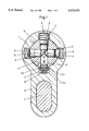
- FIG. 1 shows a cross section through a rotary locking cylinder according to the invention
- FIGS. 2a to 2c show longitudinal sections through the rotary locking cylinder with partial views of a key shaft.
- FIG. 3 shows a conventional double cylinder lock connected by a connecting web.
- the rotary locking cylinder has a housing with a continuous bore hole 5 in which a rotor 9 is inserted.
- Spring-loaded tumblers with springs 4, core pins 8 and housing pins 3 are inserted into radial bore holes in the rotor 9 and into inserts 2 of the housing 1 in a known manner.
- a flat key or turn key 14 is inserted into an open key groove 10 to enable rotation.
- Key groove 10 is defined by external face 20, circumferential surface 22, and internal wall 24 of rotor 9. If the rotary locking cylinder has two individual cylinders, these cylinders are connected with one another by a web 7 inserted into the cylinder pocket 6.
- the rotary locking cylinder according to the invention can be a single rotary locking cylinder or double rotary locking cylinder.
- a recess 11 extending in the longitudinal direction of the rotary locking cylinder is worked into the housing 1 in the lower region of the bore hole 5. As will be seen from FIG. 2a, this recess is open at the rear, i.e. with reference to the figure, while it is closed in the front.
- a blocking insert 12 having two parts 12a and 12b which are T-shaped in cross section and made of brass, for example, is inserted into this groove-shaped recess 11.
- the parts 12a and 12b have two pocket bore holes 12c in the underside, spiral springs 13 being inserted into the latter.
- the spiral springs 13 supported at the housing 1 hold parts 12a and 12b in the position shown in FIGS. 1 and 2a.
- the rotary locking cylinder can be operated in a conventional manner by inserting the correct turning key 14 into the key groove 10 as is shown in FIGS. 2b and 2c.
- part 12a first and then part 12b are moved downward into the recess 11 against the repelling force of the springs 13.
- parts 12a and 12b no longer project beyond the recess 11 at the top and also no longer engage in the key groove 10. Since the tumblers are simultaneously brought into line by the key 14, the rotor 9 is released.
- Parts 12a and 12b have a T-shaped cross section, as is shown in FIG. 1, along their entire length. Accordingly, they have an upper projection 12c which is only slightly narrower than the key groove 10.
- a lower region 12e is wider than the key groove 10 and only slightly narrower than the recess 11. The wider region 12e accordingly forms a stop which prevents parts 12a and 12b from being pressed completely into the key groove 10 by the springs 13. When the key 14 is removed, parts 12a and 12b immediately move automatically into the position shown in FIG. 2a.
Landscapes
- Lock And Its Accessories (AREA)
- Perforating, Stamping-Out Or Severing By Means Other Than Cutting (AREA)
- Underground Structures, Protecting, Testing And Restoring Foundations (AREA)
- Actuator (AREA)
- Snaps, Bayonet Connections, Set Pins, And Snap Rings (AREA)
Applications Claiming Priority (2)
| Application Number | Priority Date | Filing Date | Title |
|---|---|---|---|
| EP93810702 | 1993-10-05 | ||
| EP93810702A EP0646689B1 (de) | 1991-09-19 | 1993-10-05 | Drehschliesszylinder für ein Sicherheitsschloss |
Publications (1)
| Publication Number | Publication Date |
|---|---|
| US5553473A true US5553473A (en) | 1996-09-10 |
Family
ID=8215040
Family Applications (1)
| Application Number | Title | Priority Date | Filing Date |
|---|---|---|---|
| US08/293,382 Expired - Fee Related US5553473A (en) | 1993-10-05 | 1994-08-19 | Rotary locking cylinder for a safety lock |
Country Status (4)
| Country | Link |
|---|---|
| US (1) | US5553473A (de) |
| AT (1) | ATE160200T1 (de) |
| DE (1) | DE59307682D1 (de) |
| ES (1) | ES2109466T3 (de) |
Cited By (5)
| Publication number | Priority date | Publication date | Assignee | Title |
|---|---|---|---|---|
| US5893285A (en) * | 1998-02-10 | 1999-04-13 | Athanassiou; George | Lock cylinder |
| US6240670B1 (en) | 1999-09-03 | 2001-06-05 | Ra Brands, L.L.C. | Locking mechanism for firearms |
| US20050274162A1 (en) * | 2004-06-15 | 2005-12-15 | Keso Ag | Locking cylinder |
| US20100050716A1 (en) * | 2008-09-04 | 2010-03-04 | Abus August Bremicker Soehne Kg | Lock cylinder |
| EP2993284A1 (de) * | 2014-08-26 | 2016-03-09 | DORMA Deutschland GmbH | Zylinderkörper für einen zylinder für schlösser |
Citations (7)
| Publication number | Priority date | Publication date | Assignee | Title |
|---|---|---|---|---|
| US772112A (en) * | 1904-03-29 | 1904-10-11 | Julius Oleschak | Lock. |
| US1958603A (en) * | 1932-11-29 | 1934-05-15 | William T Bacon | Lock |
| US2003086A (en) * | 1933-03-31 | 1935-05-28 | Briggs & Stratton Corp | Cylinder lock |
| US2408283A (en) * | 1944-12-27 | 1946-09-24 | Morey E Wollin | Lock |
| US2879658A (en) * | 1954-08-13 | 1959-03-31 | Theodore H Johnstone | Cylinder lock |
| US3455130A (en) * | 1967-11-15 | 1969-07-15 | Ilco Corp | Pickproof lock |
| US4760722A (en) * | 1987-05-21 | 1988-08-02 | Tong Lung Metal Industry Co. Ltd. | Cylinder lock |
-
1993
- 1993-10-05 DE DE59307682T patent/DE59307682D1/de not_active Expired - Lifetime
- 1993-10-05 ES ES93810702T patent/ES2109466T3/es not_active Expired - Lifetime
- 1993-10-05 AT AT93810702T patent/ATE160200T1/de not_active IP Right Cessation
-
1994
- 1994-08-19 US US08/293,382 patent/US5553473A/en not_active Expired - Fee Related
Patent Citations (7)
| Publication number | Priority date | Publication date | Assignee | Title |
|---|---|---|---|---|
| US772112A (en) * | 1904-03-29 | 1904-10-11 | Julius Oleschak | Lock. |
| US1958603A (en) * | 1932-11-29 | 1934-05-15 | William T Bacon | Lock |
| US2003086A (en) * | 1933-03-31 | 1935-05-28 | Briggs & Stratton Corp | Cylinder lock |
| US2408283A (en) * | 1944-12-27 | 1946-09-24 | Morey E Wollin | Lock |
| US2879658A (en) * | 1954-08-13 | 1959-03-31 | Theodore H Johnstone | Cylinder lock |
| US3455130A (en) * | 1967-11-15 | 1969-07-15 | Ilco Corp | Pickproof lock |
| US4760722A (en) * | 1987-05-21 | 1988-08-02 | Tong Lung Metal Industry Co. Ltd. | Cylinder lock |
Cited By (7)
| Publication number | Priority date | Publication date | Assignee | Title |
|---|---|---|---|---|
| US5893285A (en) * | 1998-02-10 | 1999-04-13 | Athanassiou; George | Lock cylinder |
| US6240670B1 (en) | 1999-09-03 | 2001-06-05 | Ra Brands, L.L.C. | Locking mechanism for firearms |
| US20050274162A1 (en) * | 2004-06-15 | 2005-12-15 | Keso Ag | Locking cylinder |
| US7181937B2 (en) * | 2004-06-15 | 2007-02-27 | Keso Ag | Locking cylinder |
| US20100050716A1 (en) * | 2008-09-04 | 2010-03-04 | Abus August Bremicker Soehne Kg | Lock cylinder |
| US8875552B2 (en) * | 2008-09-04 | 2014-11-04 | ABUS August Bremicker Söhne KG | Lock cylinder |
| EP2993284A1 (de) * | 2014-08-26 | 2016-03-09 | DORMA Deutschland GmbH | Zylinderkörper für einen zylinder für schlösser |
Also Published As
| Publication number | Publication date |
|---|---|
| DE59307682D1 (de) | 1997-12-18 |
| ES2109466T3 (es) | 1998-01-16 |
| ATE160200T1 (de) | 1997-11-15 |
Similar Documents
| Publication | Publication Date | Title |
|---|---|---|
| US5666835A (en) | Key and installation double cylinder for a security lock | |
| CA1057525A (en) | Rotary plug cylinder lock construction | |
| US6910356B2 (en) | Anti-pick mogul cylinder | |
| US4377940A (en) | Impression-resistant lock | |
| CA2681671C (en) | Hierarchical cylinder lock system | |
| US4103526A (en) | Pin tumbler lock | |
| US4630457A (en) | Lock with removable plug | |
| US5079936A (en) | High security cylinder lock | |
| GB2101669A (en) | Cylinder lock | |
| US5617750A (en) | Pin tumbler locks and keys therefor | |
| US4208894A (en) | Cam lock | |
| US4062211A (en) | Rotary plug cylinder lock | |
| US4576025A (en) | Magnetic lock insert for lock mechanisms | |
| GB2556336A (en) | Improvements to lock cylinders | |
| US5553473A (en) | Rotary locking cylinder for a safety lock | |
| US6755062B2 (en) | Anti-pick mogul deadlock | |
| US11306507B2 (en) | High security locking system which forms a deviating picking path and associated deviated key | |
| US3448599A (en) | Key-operated lock mounting and removing arrangement | |
| US6119496A (en) | Keys for high security cylinder lock systems | |
| CA2133589A1 (en) | Rotary locking cylinder for a safety lock | |
| US4580425A (en) | High security lock | |
| EP3708744B1 (de) | Codierungsverfahren eines stiftsperres | |
| GB2358670A (en) | Key and cylinder lock | |
| GB2230555A (en) | Cylinder locks | |
| AU666369B2 (en) | Improvements in pin tumbler locks and keys therefor |
Legal Events
| Date | Code | Title | Description |
|---|---|---|---|
| FEPP | Fee payment procedure |
Free format text: PAYOR NUMBER ASSIGNED (ORIGINAL EVENT CODE: ASPN); ENTITY STATUS OF PATENT OWNER: SMALL ENTITY |
|
| FPAY | Fee payment |
Year of fee payment: 4 |
|
| FEPP | Fee payment procedure |
Free format text: PAYOR NUMBER ASSIGNED (ORIGINAL EVENT CODE: ASPN); ENTITY STATUS OF PATENT OWNER: SMALL ENTITY Free format text: PAYER NUMBER DE-ASSIGNED (ORIGINAL EVENT CODE: RMPN); ENTITY STATUS OF PATENT OWNER: SMALL ENTITY |
|
| FPAY | Fee payment |
Year of fee payment: 8 |
|
| REMI | Maintenance fee reminder mailed | ||
| LAPS | Lapse for failure to pay maintenance fees | ||
| STCH | Information on status: patent discontinuation |
Free format text: PATENT EXPIRED DUE TO NONPAYMENT OF MAINTENANCE FEES UNDER 37 CFR 1.362 |
|
| FP | Lapsed due to failure to pay maintenance fee |
Effective date: 20080910 |