US5573230A - Device for blocking a piece on a support plane like a table for operating machines - Google Patents
Device for blocking a piece on a support plane like a table for operating machines Download PDFInfo
- Publication number
- US5573230A US5573230A US08/378,731 US37873195A US5573230A US 5573230 A US5573230 A US 5573230A US 37873195 A US37873195 A US 37873195A US 5573230 A US5573230 A US 5573230A
- Authority
- US
- United States
- Prior art keywords
- hub
- pin
- blocking device
- support plane
- piece
- Prior art date
- Legal status (The legal status is an assumption and is not a legal conclusion. Google has not performed a legal analysis and makes no representation as to the accuracy of the status listed.)
- Expired - Fee Related
Links
Images


Classifications
-
- B—PERFORMING OPERATIONS; TRANSPORTING
- B25—HAND TOOLS; PORTABLE POWER-DRIVEN TOOLS; MANIPULATORS
- B25B—TOOLS OR BENCH DEVICES NOT OTHERWISE PROVIDED FOR, FOR FASTENING, CONNECTING, DISENGAGING, OR HOLDING
- B25B5/00—Clamps
- B25B5/06—Arrangements for positively actuating jaws
- B25B5/08—Arrangements for positively actuating jaws using cams
Definitions
- the present invention refers to a device for blocking a piece on a support plane, like a table for an operating machine or for similar applications.
- the object of the present invention is the realization of a device of this type having a simple and solid structure and of general employment, such as to permit, in cooperation with similar devices, the secure blocking of pieces having the most varied, even irregular, shapes.
- this object is obtained by means of a device similar to the consedered type, characterized by the fact that it comprises:
- a central pin provided with means for its secure blocking to the support plane with the axis of the pin perpendicular to the plane itself;
- an anular hub freely rotating around the pin, provided with driving means for its rotation and having a periphericai male screw cuttingeccentric in relation to the axis of the pin;
- a ring nut having an internal screw cutting, coupled to the external screw cutting of the hub and presenting on its periphery at least a face for laterally engaging the piece, like a thightening jaw, the coupled screw cuttings of the hub and of the ring nut having an irreversible pitch.
- FIG. 1 is a perspective view illustrating a table for operating machine on which a piece to be worked is fixed by blocking means according to the invention
- FIG. 2 is a perspective, in large scale view, of a position of FIG. 1, in which one of the blocking devices and one corresponding control key, of the same devices are illustrated,
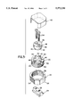
- FIG. 3 ia a view in exploded perspective of the blocking device and of its protective cap
- FIG. 4 is a plan view of the blocking device
- FIG. 5 is a diametral sectional view in association with the table and the piece, partially represented.
- a table for an operating machine presents the ordinary T-Shaped fixing grooves, indicated with 12.
- Checking means, fixed to the table 10, are designed with 14.
- a piece to be worked is indicated with W, and is fixed to the table 10 by means of three similar fixing devices, according to the invention, all designed with 16.
- the piece W has been conventionally represesented in the form of a prismatic block; but it might have any other shape, even an irregular one.
- a fixing device 16 comprises a central steel hub 20, free to rotate around the pin 18, and a steel ring nut 22.
- a T-shaped steel key 24 is joined to the pin 18, as illustrated in the FIGS. 2 to 5, and is inserted in one of the grooves 12.
- the pin 18 presents at least a longitudinal passing bore and, preferably, as represented, a couple of these bores, designated as 26 and disposed on a diameter at the same distance from the axis of the pin 18.
- Each bore 26 comprises (FIG. 5) a blinded portion 28 and a smooth portion 30.
- the key 24 presents a couple of threaded bores 32.
- the fixing of the pin 18 to the table 10 occurs by means of a couple of screws 34 of the internal hexagon type.
- the heads of these screws remain encased in the blinded portions 28, their stems go through the smooth portions of the passing bores 26 and their threaded portions couple with the threaded bores 32 of the key 12.
- the pin 18 comprises a cylindrical section of greater diameter 36 and a cylindrical following section of smaller diameter 38, so that it forms a ring-like seat 40 which, by the use, is turned toward the table 10.
- the hub 20 presents a central bore 42 having cylindrical following portions of greater diameter 44 and smaller diameter 46 respectively.
- the portions of greater and smaller diameter of the hub 20 are coupled with the corresponding portions of the pin 18, such as to permit the hub 20 to rotate freely, but precisely, around the axis of the pin 18.
- a ring-like seat is defined, which co-operates with the seat 40 for confining the hub 20 and preventing its removal from the table 10, when the pin 18 is fixed to the same table.
- the annular hub 20 has external threads 50.
- the threads 50 are eccentric to the common rotation axis of the bore 40 and of the pin 18
- the rotation axis is indicated as A and the axis of the threads 50 is indicated as E.
- the ring nut 22 which encircles the hub 20 is provided with internal threads 52 coupled with threads of the hub 20.
- the same ring nut 22 presents on its periphery at least a flat face to laterally engage the piece W and to tighten it and lock it, in cooperation with the other locking means, like a thightening jaw.
- the hub 20 is coupled with ring nut 22 and scrwes with said nut in only one position because in this position it is possible to rotate the hub 20 with the key 62.
- the ring nut 22 presents on its periphery at least a face 54 or 56 for laterally engaging the piece W, like a thightening jaw
- the ring nut 22 presents a plurality of flat engaging faces 54, 56, placed on its periphery.
- these engaging faces 54, 56 are flat, tangential ones, placed on the periphery of the ring nut 22 at 90° one from the other.
- two engaging, diametrically opposed faces 54 are knurled, as it is illustrated in the FIGS. 3 and 5, while the other two faces 56 are smooth.
- rotating driving means which comprise diametral slots 60, which, in the case represented in FIGS. 2 to 5, are oppositely disposed. These diametral slots 60 are cut out of a extremity face of the hub 20 furtherest from the table 10.
- the device 16 is provided with a key 62 (FIG. 2) which comprises for example a bush 64 provided with teeth 66 engaging the slots 60.
- the bush 64 presents diametral opposite slots 68 in which a sliding, slippable control rod may be inserted.
- the bush 64 might be provided with a lateral lever having the same function of the rod 70.
- the two opposite knurled faces 54 of the ring nut 22 present preferably a knurl formed by a set of riflings tangentially oriented in relation to the axis of the ring nut 22.
- these riflings have a saw teeth shaped contour with flat sides turned, in the use, towards the table or support plane 10. This saw teeth shaped configuration, so, oriented (FIG. 5), constitutes a guarantee against the detaching of the piece W from the table 10.
- the other two flat and smooth faces 56 are utilized for engaging a piece, like W, of tender material for avoiding damage to the surface.
- each blocking device 16 may be advantageously covered by a cap 62, for example of plastic material (FIG. 3) for protecting it from the dust, the chips, the cut oils and so on.
- a cap 62 for example of plastic material (FIG. 3) for protecting it from the dust, the chips, the cut oils and so on.
Landscapes
- Engineering & Computer Science (AREA)
- Mechanical Engineering (AREA)
- Jigs For Machine Tools (AREA)
- Perforating, Stamping-Out Or Severing By Means Other Than Cutting (AREA)
- Finish Polishing, Edge Sharpening, And Grinding By Specific Grinding Devices (AREA)
- Machine Tool Units (AREA)
- Sewing Machines And Sewing (AREA)
- Telephone Set Structure (AREA)
Priority Applications (6)
| Application Number | Priority Date | Filing Date | Title |
|---|---|---|---|
| IT94TO000056A IT1268004B1 (it) | 1994-02-02 | 1994-02-02 | Dispositivo per il bloccaggio di un pezzo su un piano d'appoggio, quale una tavola di macchina operatrice. |
| US08/378,731 US5573230A (en) | 1994-02-02 | 1995-01-26 | Device for blocking a piece on a support plane like a table for operating machines |
| EP95101298A EP0666144B1 (en) | 1994-02-02 | 1995-01-31 | Device for blocking a piece on a support plane like a table for operating machines |
| ES95101298T ES2100747T3 (es) | 1994-02-02 | 1995-01-31 | Dispositivo para bloquear una pieza sobre una superficie plana de apoyo, como una mesa, para maquinas de manipulacion. |
| DE69500232T DE69500232T2 (de) | 1994-02-02 | 1995-01-31 | Vorrichtung zum Einspannen eines Werkstücks auf einer ebenen Unterlage, wie z.B. der Tisch einer Bearbeitungsmaschine |
| AT95101298T ATE151679T1 (de) | 1994-02-02 | 1995-01-31 | Vorrichtung zum einspannen eines werkstücks auf einer ebenen unterlage, wie z.b. der tisch einer bearbeitungsmaschine |
Applications Claiming Priority (2)
| Application Number | Priority Date | Filing Date | Title |
|---|---|---|---|
| IT94TO000056A IT1268004B1 (it) | 1994-02-02 | 1994-02-02 | Dispositivo per il bloccaggio di un pezzo su un piano d'appoggio, quale una tavola di macchina operatrice. |
| US08/378,731 US5573230A (en) | 1994-02-02 | 1995-01-26 | Device for blocking a piece on a support plane like a table for operating machines |
Publications (1)
| Publication Number | Publication Date |
|---|---|
| US5573230A true US5573230A (en) | 1996-11-12 |
Family
ID=26332245
Family Applications (1)
| Application Number | Title | Priority Date | Filing Date |
|---|---|---|---|
| US08/378,731 Expired - Fee Related US5573230A (en) | 1994-02-02 | 1995-01-26 | Device for blocking a piece on a support plane like a table for operating machines |
Country Status (6)
| Country | Link |
|---|---|
| US (1) | US5573230A (it) |
| EP (1) | EP0666144B1 (it) |
| AT (1) | ATE151679T1 (it) |
| DE (1) | DE69500232T2 (it) |
| ES (1) | ES2100747T3 (it) |
| IT (1) | IT1268004B1 (it) |
Cited By (17)
| Publication number | Priority date | Publication date | Assignee | Title |
|---|---|---|---|---|
| US5933941A (en) * | 1997-09-02 | 1999-08-10 | Haeger, Inc. | Cantilevered X-Y positioning system for fastener insertion machine |
| US6276676B1 (en) * | 1999-07-30 | 2001-08-21 | Excellon Automation Company | Manual registration pin alignment system |
| US6375134B1 (en) | 2000-04-13 | 2002-04-23 | Ronald A. Rohm | Adjustable container holder |
| US6530302B1 (en) | 2000-08-25 | 2003-03-11 | William H. Rogers | Cabinetmaking system |
| US6585244B2 (en) * | 2000-06-14 | 2003-07-01 | J. Schmalz Gmbh | Work table for supporting a workpiece |
| US20030166872A1 (en) * | 1999-06-24 | 2003-09-04 | Huse William D. | Anti- alphavbeta3 recombinant human antibodies, nucleic acids encoding same and methods of use |
| US20030208048A1 (en) * | 1997-01-30 | 2003-11-06 | Ixsys, Inc. | Anti-alphavbeta3 recombinant human antibodies, nucleic acids encoding same and methods of use |
| US6662699B1 (en) * | 2002-01-07 | 2003-12-16 | Great Neck Saw Manufacturers, Inc. | Miter box |
| US6694851B2 (en) * | 2000-03-29 | 2004-02-24 | James S. Erisoty | Multi-angle miter box with clamping feature |
| US20050069554A1 (en) * | 1997-01-30 | 2005-03-31 | Applied Molecular Evolution, Inc. | Anti-alphavbeta3 recombinant human antibodies, nucleic acids encoding same and methods of use |
| US20100000387A1 (en) * | 2008-07-02 | 2010-01-07 | Thacker Thomas M | Guide bar track extension method and apparatus |
| US20120037579A1 (en) * | 2010-08-13 | 2012-02-16 | Muldoon Patrick T | Gun and fishing rod holder |
| US20140300042A1 (en) * | 2013-04-03 | 2014-10-09 | Mike Ursell | Straight edge clamp |
| US20150283679A1 (en) * | 2014-04-03 | 2015-10-08 | Michael Ursell | Straight Edge Clamp |
| US20150283680A1 (en) * | 2014-04-03 | 2015-10-08 | Michael Ursell | Hinged Straight Edge Clamp |
| US10442101B2 (en) * | 2013-05-03 | 2019-10-15 | Samsung Display Co., Ltd. | Method for aligning substrate and apparatus for cutting substrate using the same |
| US12655859B1 (en) * | 2025-10-06 | 2026-06-16 | Henry Wang | Reversible dovetail clamp with notches |
Families Citing this family (2)
| Publication number | Priority date | Publication date | Assignee | Title |
|---|---|---|---|---|
| FR2767731B1 (fr) * | 1997-09-03 | 1999-10-29 | Carossino Patricia | Element de poussee horizontale pour dispositif de bridage horizontal |
| GB0329268D0 (en) * | 2003-12-17 | 2004-01-21 | Rolls Royce Plc | Method and apparatus for heat-treating an article and a fixture for use in the same |
Citations (4)
| Publication number | Priority date | Publication date | Assignee | Title |
|---|---|---|---|---|
| US449039A (en) * | 1891-03-24 | Herman fietscit | ||
| US4477064A (en) * | 1982-06-09 | 1984-10-16 | Digiulio Mario | Device for holding work in machine tool operations |
| US4805888A (en) * | 1986-03-10 | 1989-02-21 | Bishop Maurice E | Orbital-action clamps |
| US4915367A (en) * | 1987-09-15 | 1990-04-10 | Carossino Freres | Clamping apparatus for parts to be machined |
Family Cites Families (3)
| Publication number | Priority date | Publication date | Assignee | Title |
|---|---|---|---|---|
| FR2112262B1 (it) * | 1970-10-07 | 1975-01-17 | Harding Crosweller Ltd | |
| JP2849593B2 (ja) * | 1986-03-10 | 1999-01-20 | イー.ビショップ モーリス | 軌道運動作用クランプ |
| DE8715602U1 (de) * | 1987-11-25 | 1988-03-03 | Stenzel & Co Maschinenhandelsgesellschaft mbH, 6200 Wiesbaden | Vorrichtung zum Aufspannen von Gegenständen auf einer tischförmigen Unterlage |
-
1994
- 1994-02-02 IT IT94TO000056A patent/IT1268004B1/it active IP Right Grant
-
1995
- 1995-01-26 US US08/378,731 patent/US5573230A/en not_active Expired - Fee Related
- 1995-01-31 DE DE69500232T patent/DE69500232T2/de not_active Expired - Fee Related
- 1995-01-31 AT AT95101298T patent/ATE151679T1/de active
- 1995-01-31 EP EP95101298A patent/EP0666144B1/en not_active Expired - Lifetime
- 1995-01-31 ES ES95101298T patent/ES2100747T3/es not_active Expired - Lifetime
Patent Citations (4)
| Publication number | Priority date | Publication date | Assignee | Title |
|---|---|---|---|---|
| US449039A (en) * | 1891-03-24 | Herman fietscit | ||
| US4477064A (en) * | 1982-06-09 | 1984-10-16 | Digiulio Mario | Device for holding work in machine tool operations |
| US4805888A (en) * | 1986-03-10 | 1989-02-21 | Bishop Maurice E | Orbital-action clamps |
| US4915367A (en) * | 1987-09-15 | 1990-04-10 | Carossino Freres | Clamping apparatus for parts to be machined |
Cited By (26)
| Publication number | Priority date | Publication date | Assignee | Title |
|---|---|---|---|---|
| US20030208048A1 (en) * | 1997-01-30 | 2003-11-06 | Ixsys, Inc. | Anti-alphavbeta3 recombinant human antibodies, nucleic acids encoding same and methods of use |
| US20050069554A1 (en) * | 1997-01-30 | 2005-03-31 | Applied Molecular Evolution, Inc. | Anti-alphavbeta3 recombinant human antibodies, nucleic acids encoding same and methods of use |
| US5933941A (en) * | 1997-09-02 | 1999-08-10 | Haeger, Inc. | Cantilevered X-Y positioning system for fastener insertion machine |
| US20030166872A1 (en) * | 1999-06-24 | 2003-09-04 | Huse William D. | Anti- alphavbeta3 recombinant human antibodies, nucleic acids encoding same and methods of use |
| US6276676B1 (en) * | 1999-07-30 | 2001-08-21 | Excellon Automation Company | Manual registration pin alignment system |
| US6694851B2 (en) * | 2000-03-29 | 2004-02-24 | James S. Erisoty | Multi-angle miter box with clamping feature |
| US6375134B1 (en) | 2000-04-13 | 2002-04-23 | Ronald A. Rohm | Adjustable container holder |
| US6585244B2 (en) * | 2000-06-14 | 2003-07-01 | J. Schmalz Gmbh | Work table for supporting a workpiece |
| US6530302B1 (en) | 2000-08-25 | 2003-03-11 | William H. Rogers | Cabinetmaking system |
| US6662699B1 (en) * | 2002-01-07 | 2003-12-16 | Great Neck Saw Manufacturers, Inc. | Miter box |
| US20100000387A1 (en) * | 2008-07-02 | 2010-01-07 | Thacker Thomas M | Guide bar track extension method and apparatus |
| US8375835B2 (en) | 2008-07-02 | 2013-02-19 | Thomas M. Thacker | Guide bar track extension method and apparatus |
| US20120160791A1 (en) * | 2010-08-13 | 2012-06-28 | Chrysler Group Llc | Gun and fishing rod holder |
| US20120037579A1 (en) * | 2010-08-13 | 2012-02-16 | Muldoon Patrick T | Gun and fishing rod holder |
| US8651289B2 (en) * | 2010-08-13 | 2014-02-18 | Chrysler Group Llc | Gun and fishing rod holder |
| US8657127B2 (en) * | 2010-08-13 | 2014-02-25 | Chrysler Group Llc | Gun and fishing rod holder |
| US10478947B2 (en) * | 2013-04-03 | 2019-11-19 | Affinity Tool Works, Llc | Straight edge clamp |
| US20140300042A1 (en) * | 2013-04-03 | 2014-10-09 | Mike Ursell | Straight edge clamp |
| US10987782B2 (en) | 2013-04-03 | 2021-04-27 | Affinity Tool Works, Llc | Straight edge clamp |
| US10442101B2 (en) * | 2013-05-03 | 2019-10-15 | Samsung Display Co., Ltd. | Method for aligning substrate and apparatus for cutting substrate using the same |
| US20150283679A1 (en) * | 2014-04-03 | 2015-10-08 | Michael Ursell | Straight Edge Clamp |
| US20150283680A1 (en) * | 2014-04-03 | 2015-10-08 | Michael Ursell | Hinged Straight Edge Clamp |
| US9815177B2 (en) * | 2014-04-03 | 2017-11-14 | Affinity Tool Works, Llc | Straight edge clamp |
| US9975221B2 (en) * | 2014-04-03 | 2018-05-22 | Affinity Tool Works, Llc | Hinged straight edge clamp |
| US10661413B2 (en) | 2014-04-03 | 2020-05-26 | Affinity Tool Works, Llc | Straight edge clamp |
| US12655859B1 (en) * | 2025-10-06 | 2026-06-16 | Henry Wang | Reversible dovetail clamp with notches |
Also Published As
| Publication number | Publication date |
|---|---|
| IT1268004B1 (it) | 1997-02-20 |
| ITTO940056A0 (it) | 1994-02-02 |
| ITTO940056A1 (it) | 1995-08-02 |
| EP0666144B1 (en) | 1997-04-16 |
| DE69500232T2 (de) | 1997-07-24 |
| EP0666144A1 (en) | 1995-08-09 |
| ATE151679T1 (de) | 1997-05-15 |
| DE69500232D1 (de) | 1997-05-22 |
| ES2100747T3 (es) | 1997-06-16 |
Similar Documents
| Publication | Publication Date | Title |
|---|---|---|
| EP0666144B1 (en) | Device for blocking a piece on a support plane like a table for operating machines | |
| US5518440A (en) | Power tool flange lock | |
| US3912411A (en) | Thread latching mechanism | |
| US4325664A (en) | Cutting tool | |
| US3440915A (en) | Quick release connection | |
| US3664213A (en) | Wrench | |
| US3618994A (en) | Arbor nut | |
| US6966115B2 (en) | Pruning scissors | |
| US5020280A (en) | Grinding tool and spacer assembly for use therein | |
| EP0636455B1 (en) | A clamp nut | |
| CA2686080C (en) | Security screw | |
| US5035550A (en) | Hole saw | |
| US6467990B1 (en) | Arrangement for securing a component | |
| US11311988B2 (en) | Torque connector | |
| US5090126A (en) | Rotary tool quick acting retention device | |
| US6004079A (en) | Cutter head, in particular a profile cutter head | |
| JP5043687B2 (ja) | スイングボルト構造を含む工具 | |
| US3408924A (en) | Die locking | |
| JPH01135416A (ja) | ねじ山の修理具 | |
| US5590991A (en) | Locking device | |
| US4487533A (en) | Mount for milling tool bits | |
| US4400960A (en) | Tool for setting blind fasteners | |
| JPH06249221A (ja) | ボルトおよびナットのゆるみ止め装置 | |
| US4012157A (en) | Connecting device | |
| US3074519A (en) | Fastening means |
Legal Events
| Date | Code | Title | Description |
|---|---|---|---|
| AS | Assignment |
Owner name: OFFICINA MECCANICA LOMBARDA S.R.L., ITALY Free format text: ASSIGNMENT OF ASSIGNORS INTEREST;ASSIGNOR:LAMBERTINI, GIUSEPPE;REEL/FRAME:007344/0610 Effective date: 19950110 |
|
| REMI | Maintenance fee reminder mailed | ||
| LAPS | Lapse for failure to pay maintenance fees | ||
| FP | Lapsed due to failure to pay maintenance fee |
Effective date: 20001112 |
|
| STCH | Information on status: patent discontinuation |
Free format text: PATENT EXPIRED DUE TO NONPAYMENT OF MAINTENANCE FEES UNDER 37 CFR 1.362 |