US5606324A - Radar system - Google Patents
Radar system Download PDFInfo
- Publication number
- US5606324A US5606324A US08/569,374 US56937495A US5606324A US 5606324 A US5606324 A US 5606324A US 56937495 A US56937495 A US 56937495A US 5606324 A US5606324 A US 5606324A
- Authority
- US
- United States
- Prior art keywords
- range
- tracking error
- series
- frequency
- pulses
- Prior art date
- Legal status (The legal status is an assumption and is not a legal conclusion. Google has not performed a legal analysis and makes no representation as to the accuracy of the status listed.)
- Expired - Fee Related
Links
Images


Classifications
-
- G—PHYSICS
- G01—MEASURING; TESTING
- G01S—RADIO DIRECTION-FINDING; RADIO NAVIGATION; DETERMINING DISTANCE OR VELOCITY BY USE OF RADIO WAVES; LOCATING OR PRESENCE-DETECTING BY USE OF THE REFLECTION OR RERADIATION OF RADIO WAVES; ANALOGOUS ARRANGEMENTS USING OTHER WAVES
- G01S13/00—Systems using the reflection or reradiation of radio waves, e.g. radar systems; Analogous systems using reflection or reradiation of waves whose nature or wavelength is irrelevant or unspecified
- G01S13/02—Systems using reflection of radio waves, e.g. primary radar systems; Analogous systems
- G01S13/50—Systems of measurement based on relative movement of target
- G01S13/52—Discriminating between fixed and moving objects or between objects moving at different speeds
- G01S13/522—Discriminating between fixed and moving objects or between objects moving at different speeds using transmissions of interrupted pulse modulated waves
- G01S13/524—Discriminating between fixed and moving objects or between objects moving at different speeds using transmissions of interrupted pulse modulated waves based upon the phase or frequency shift resulting from movement of objects, with reference to the transmitted signals, e.g. coherent MTi
- G01S13/53—Discriminating between fixed and moving objects or between objects moving at different speeds using transmissions of interrupted pulse modulated waves based upon the phase or frequency shift resulting from movement of objects, with reference to the transmitted signals, e.g. coherent MTi performing filtering on a single spectral line and associated with one or more range gates with a phase detector or a frequency mixer to extract the Doppler information, e.g. pulse Doppler radar
-
- G—PHYSICS
- G01—MEASURING; TESTING
- G01S—RADIO DIRECTION-FINDING; RADIO NAVIGATION; DETERMINING DISTANCE OR VELOCITY BY USE OF RADIO WAVES; LOCATING OR PRESENCE-DETECTING BY USE OF THE REFLECTION OR RERADIATION OF RADIO WAVES; ANALOGOUS ARRANGEMENTS USING OTHER WAVES
- G01S13/00—Systems using the reflection or reradiation of radio waves, e.g. radar systems; Analogous systems using reflection or reradiation of waves whose nature or wavelength is irrelevant or unspecified
- G01S13/02—Systems using reflection of radio waves, e.g. primary radar systems; Analogous systems
- G01S13/06—Systems determining position data of a target
- G01S13/08—Systems for measuring distance only
- G01S13/10—Systems for measuring distance only using transmission of interrupted, pulse modulated waves
- G01S13/24—Systems for measuring distance only using transmission of interrupted, pulse modulated waves using frequency agility of carrier wave
-
- G—PHYSICS
- G01—MEASURING; TESTING
- G01S—RADIO DIRECTION-FINDING; RADIO NAVIGATION; DETERMINING DISTANCE OR VELOCITY BY USE OF RADIO WAVES; LOCATING OR PRESENCE-DETECTING BY USE OF THE REFLECTION OR RERADIATION OF RADIO WAVES; ANALOGOUS ARRANGEMENTS USING OTHER WAVES
- G01S13/00—Systems using the reflection or reradiation of radio waves, e.g. radar systems; Analogous systems using reflection or reradiation of waves whose nature or wavelength is irrelevant or unspecified
- G01S13/66—Radar-tracking systems; Analogous systems
-
- G—PHYSICS
- G01—MEASURING; TESTING
- G01S—RADIO DIRECTION-FINDING; RADIO NAVIGATION; DETERMINING DISTANCE OR VELOCITY BY USE OF RADIO WAVES; LOCATING OR PRESENCE-DETECTING BY USE OF THE REFLECTION OR RERADIATION OF RADIO WAVES; ANALOGOUS ARRANGEMENTS USING OTHER WAVES
- G01S13/00—Systems using the reflection or reradiation of radio waves, e.g. radar systems; Analogous systems using reflection or reradiation of waves whose nature or wavelength is irrelevant or unspecified
- G01S13/02—Systems using reflection of radio waves, e.g. primary radar systems; Analogous systems
- G01S13/06—Systems determining position data of a target
- G01S13/08—Systems for measuring distance only
- G01S13/10—Systems for measuring distance only using transmission of interrupted, pulse modulated waves
- G01S13/18—Systems for measuring distance only using transmission of interrupted, pulse modulated waves wherein range gates are used
-
- G—PHYSICS
- G01—MEASURING; TESTING
- G01S—RADIO DIRECTION-FINDING; RADIO NAVIGATION; DETERMINING DISTANCE OR VELOCITY BY USE OF RADIO WAVES; LOCATING OR PRESENCE-DETECTING BY USE OF THE REFLECTION OR RERADIATION OF RADIO WAVES; ANALOGOUS ARRANGEMENTS USING OTHER WAVES
- G01S13/00—Systems using the reflection or reradiation of radio waves, e.g. radar systems; Analogous systems using reflection or reradiation of waves whose nature or wavelength is irrelevant or unspecified
- G01S13/02—Systems using reflection of radio waves, e.g. primary radar systems; Analogous systems
- G01S13/06—Systems determining position data of a target
- G01S13/42—Simultaneous measurement of distance and other co-ordinates
- G01S13/44—Monopulse radar, i.e. simultaneous lobing
- G01S13/449—Combined with MTI or Doppler processing circuits
-
- G—PHYSICS
- G01—MEASURING; TESTING
- G01S—RADIO DIRECTION-FINDING; RADIO NAVIGATION; DETERMINING DISTANCE OR VELOCITY BY USE OF RADIO WAVES; LOCATING OR PRESENCE-DETECTING BY USE OF THE REFLECTION OR RERADIATION OF RADIO WAVES; ANALOGOUS ARRANGEMENTS USING OTHER WAVES
- G01S13/00—Systems using the reflection or reradiation of radio waves, e.g. radar systems; Analogous systems using reflection or reradiation of waves whose nature or wavelength is irrelevant or unspecified
- G01S13/02—Systems using reflection of radio waves, e.g. primary radar systems; Analogous systems
- G01S13/50—Systems of measurement based on relative movement of target
- G01S13/58—Velocity or trajectory determination systems; Sense-of-movement determination systems
- G01S13/64—Velocity measuring systems using range gates
-
- G—PHYSICS
- G01—MEASURING; TESTING
- G01S—RADIO DIRECTION-FINDING; RADIO NAVIGATION; DETERMINING DISTANCE OR VELOCITY BY USE OF RADIO WAVES; LOCATING OR PRESENCE-DETECTING BY USE OF THE REFLECTION OR RERADIATION OF RADIO WAVES; ANALOGOUS ARRANGEMENTS USING OTHER WAVES
- G01S13/00—Systems using the reflection or reradiation of radio waves, e.g. radar systems; Analogous systems using reflection or reradiation of waves whose nature or wavelength is irrelevant or unspecified
- G01S13/66—Radar-tracking systems; Analogous systems
- G01S13/70—Radar-tracking systems; Analogous systems for range tracking only
-
- G—PHYSICS
- G01—MEASURING; TESTING
- G01S—RADIO DIRECTION-FINDING; RADIO NAVIGATION; DETERMINING DISTANCE OR VELOCITY BY USE OF RADIO WAVES; LOCATING OR PRESENCE-DETECTING BY USE OF THE REFLECTION OR RERADIATION OF RADIO WAVES; ANALOGOUS ARRANGEMENTS USING OTHER WAVES
- G01S13/00—Systems using the reflection or reradiation of radio waves, e.g. radar systems; Analogous systems using reflection or reradiation of waves whose nature or wavelength is irrelevant or unspecified
- G01S13/66—Radar-tracking systems; Analogous systems
- G01S13/72—Radar-tracking systems; Analogous systems for two-dimensional [2D] tracking, e.g. combination of angle and range tracking, track-while-scan radar
- G01S13/723—Radar-tracking systems; Analogous systems for two-dimensional [2D] tracking, e.g. combination of angle and range tracking, track-while-scan radar by using numerical data
- G01S13/726—Multiple target tracking
-
- G—PHYSICS
- G01—MEASURING; TESTING
- G01S—RADIO DIRECTION-FINDING; RADIO NAVIGATION; DETERMINING DISTANCE OR VELOCITY BY USE OF RADIO WAVES; LOCATING OR PRESENCE-DETECTING BY USE OF THE REFLECTION OR RERADIATION OF RADIO WAVES; ANALOGOUS ARRANGEMENTS USING OTHER WAVES
- G01S7/00—Details of systems according to groups G01S13/00, G01S15/00, G01S17/00
- G01S7/02—Details of systems according to groups G01S13/00, G01S15/00, G01S17/00 of systems according to group G01S13/00
- G01S7/28—Details of pulse systems
- G01S7/285—Receivers
- G01S7/288—Coherent receivers
- G01S7/2883—Coherent receivers using FFT processing
Definitions
- This invention relates generally to radar systems and more particularly to radar systems adapted to track energy reflected by different scattering points of an object.
- a radar system includes a transmitter and antenna for transmitting and directing radar energy towards an object.
- the object reflects portions of the transmitted energy.
- a portion of the reflected energy is received by the antenna and is directed to a receiver of the radar system.
- the receiver produces signals to enable the radar system to track the object.
- the tracking signals generally track the centroid of the target's reflected energy.
- the tracking signals are fed to both the antenna and to the missile's guidance system to direct the missile toward the centroid of the target's reflected energy. In some applications, however, it is necessary to track energy from a number of different scattering points on the target.
- a radar system having a transmitter for transmitting a series of radio frequency (RF) pulses with sequential, incrementally changing carrier frequencies from pulse to pulse.
- a receiver receives energy from scattering points of an object reflecting such transmitted RF pulses.
- the received energy from each one of such scattering points includes a series of radio frequency (RF) pulses corresponding to the transmitted pulses delayed in time, ⁇ , from the transmitted pulses an amount proportional to the round trip range to such scattering point and shifted in frequency from the carrier frequency an amount proportional to the velocity of such scattering point.
- RF radio frequency
- the receiver includes a heterodyning section, responsive to a range tracking error signal, ⁇ R , and a velocity tracking error signal, ⁇ VEL , for producing a series of pulsed signals for each one of the scattering points.
- Each one of the pulsed signals sequentially changes in phase, ⁇ , at a rate, ⁇ / ⁇ T, related to the range to the scattering point producing such one of the pulsed signals.
- a processor responsive to each one of the series of pulsed signals produced by the heterodyning section, determines from the frequency spectrum thereof the range tracking error signal, ⁇ R , and velocity tracking error signal, ⁇ VEL .
- the heterodyning section includes first and second heterodyning sections.
- the first heterodyning section is fed by the series of received pulses and a series of internal reference pulses corresponding to the series of transmitted pulses delayed in time an amount related to the sum of an initial estimate of the range to a region of the object being tracked, R EST , and the range tracking error signal, ⁇ R , for producing a series of pulsed signals having frequencies related to both the velocity of the object and the ranges to the scattering points.
- the second heterodyning section is fed by the series of pulsed signals produced by the first heterodyning section, an initial estimate of the velocity of the object, V EST , and the velocity tracking error signal, ⁇ VEL , for producing a series of pulses having intermediate frequency components related to the differences between both the doppler velocity of the object and ranges to the scattering points relative to (V EST ⁇ VEL ) and (R EST ⁇ R ), respectively.
- the processor is responsive to the frequency spectrum of the series of pulses produced by the second heterodyning section and determines, from such frequency spectrum, the range tracking and velocity tracking error signals, ⁇ R , ⁇ VEL , respectively.
- the second heterodyning section includes a bandpass filter section for passing frequency components within a predetermined pass band while rejecting frequency components outside such pass band.
- the bandpass filter section has the pass band thereof selected to pass the frequency components related to the changes in both the velocity of the object and the ranges to the scattering points.
- the processor in response to the frequency spectrum of the signals passed by the bandpass filter section determines, from such frequency spectrum of the passed signals, the frequency components thereof and from such frequency components, the range and velocity tracking error signals, ⁇ R , ⁇ VEL , respectively.
- the second heterodyning section includes a range gating section fed by the range tracking error signal, ⁇ R , for passing to the bandpass filter section intermediate frequency signals associated with reflections from the scatterers of the object within a predetermined window, ⁇ R , of ranges.
- the processor determines the frequency Components in the bipolar range error signal, SG, each corresponding to a different one of the scatterers, and from such determined frequency components, the range tracking and velocity tracking error signals, ⁇ R , ⁇ VEL , respectively.
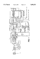
- FIG. 1 is a block diagram of a radar system according to the invention. to the invention;
- FIG. 2 is a more detailed block diagram of the radar system of FIG. 1;
- FIGS. 3A-3D are diagrams useful in understanding the operation of the radar system of FIG. 1, FIG. 3A being a time history of the carrier frequency of a series of pulses transmitted by the radar system, FIG. 3B being a time history of radar returns from a scattering point of an object reflecting the transmitted radar pulses; FIG. 3C being a representative time history of the difference in phase between the transmitted pulses and the received pulses of a particular one of the scatterers having a small range error, and FIG. 3D being a diagram showing the relationship between the rate of change in phase between the transmitted pulses and the received pulses for scattering points at different ranges from the radar system of FIGS. 1 and 2;
- FIGS. 4A-4H are timing histories useful in understanding the operation of the radar system of FIGS. 1 and 2;
- FIG. 5 is a diagram showing the frequency spectrum of returns in a sum channel, ⁇ , of the radar system of FIGS. 1 and 2;
- FIG. 6 is a diagram showing the frequency spectrum of returns in a bipolar range error signal, SG, produced in the radar system of FIGS. 1 and 2, normalized by the spectrum in the sum channel, ⁇ , together with a network for determining a range tracking error, ⁇ R , signal used in the radar system of FIGS. 1 and 2;
- FIG. 10 shows the frequency spectrum under the condition when the object has a range tracking error an no velocity tracking error
- FIG. 11 shows the frequency spectrum under the condition when the object has a range tracking error and a velocity tracking error.
- a radar system 10 having: a transmitter 12 for transmitting a series of radio frequency (RF) pulses having sequential, incrementally changing carrier frequencies from pulse to pulse and a receiver 14 adapted to receive energy from scattering points S 1 -S m of an object 16 reflecting such transmitted RF pulses.
- the received energy from each one of such scattering points S 1 -S m comprises a series of radio frequency (RF) pulses corresponding to the transmitted pulses delayed in time from the transmitted pulses an amount, ⁇ , proportional to the round trip range to such scattering point and shifted in frequency from the carrier frequency an amount proportional to the doppler velocity of such scattering point.
- RF radio frequency
- the receiver 14 includes a heterodyning section 18, fed by a range tracking error signal, ⁇ R , on line 20, a doppler velocity tracking error signal, ⁇ VEL , on line 22, and an initial estimate of the range, R EST , to the object 16 on line 21 and an initial estimate of the doppler velocity of the object 16 on line 23, V EST .
- a range tracking error signal ⁇ R
- ⁇ VEL doppler velocity tracking error signal
- R EST initial estimate of the range
- the heterodyning section 18 produces on output 19 a series of pulsed signals from the series of pulses produced from the reflected energy by each one of the scattering points S 1 -S m .
- the radar system 10 includes a processor 24 responsive to each one of the series of pulsed signals produced at output 19 by the heterodyning section 18, for determining from the frequency spectrum thereof (i.e., the frequencies (f S1 ⁇ f d )+(f S2 ⁇ f d )+(f S3 ⁇ f d ) . . . +(f Sm ⁇ f d ), the range tracking error and velocity tracking error signals, ⁇ R , ⁇ VEL , respectively, on lines 20 and 22, respectively.
- the monopulse radar system 10 is a monopulse radar system where the transmitter section 12 and receiver section 14 share a conventional monopulse antenna 26, monopulse arithmetic unit 28, circulator 30, transmit/receive (T/R) switch 32, intermediate frequency oscillator 34, stable local oscillator (STALO) 36, and direct digital synthesizer (DDS) 38, as shown.
- transmitter section 12 shown in detail in FIG.
- Each one of the pulses has a time duration, or pulse width, W.
- the carrier frequencies, f T , of the pulses produced at times t 1 to t n are f O +f If1 +f 1 to f O +f IF1 +[f 1 +(n-1) ⁇ ], respectively, as shown in FIG. 3A.
- the stable local oscillator (STALO) 36 shared by the transmitter 12 and receiver 14, produces a radio frequency signal having a frequency f O .
- the STALO 36 produced signal and the DDS 38 produced series of pulses are mixed in mixer 42 and then filtered in band pass filter 44 to produce, for each CPI, a series of pulses having sequentially increasing beat frequencies f O +f l to f O +(f 1 +(n-1) ⁇ ).
- the receiver 14 is adapted to receive energy from scattering points S 1 -S m of an object 16 reflecting such transmitted RF pulses.
- the received energy from each one of such scattering points, say point S i comprises a series of radio frequency (RF) pulses (RCVD) corresponding to the transmitted pulses delayed in time, ⁇ i , from the series of transmitted pulses an amount proportional to the range, R i , to such scattering point, S i .
- RF radio frequency
- each one of the reflections from each one of the scatterers S 1 -S m is shifted in frequency from the carrier frequency, f T , an amount, f d , proportional to the doppler velocity of such scattering point and commonly referred to as the doppler frequency shift.
- the doppler frequency, f d will be the same for each of the scattering points, S 1 -S m .
- the amount ⁇ is a function of the round trip range from antenna 26 to the particular one of the scattering points S 1 -S m producing the train of received pulses.
- the receiver 14 includes two serially coupled heterodyning sections 48, 50.
- the azimuth channel signal ( ⁇ AZ), elevation channel signal ( ⁇ EL) and sum channel signal ( ⁇ ) are produced in a conventional manner by the monopulse arithmetic unit 28 and are passed to mixers 52, 54 and 56, as shown.
- the signals produced by the DDS 38 on line 41 are the same series of pulses produced by the DDS 38 on line 39 but delayed in time ⁇ c .
- the DDS 38 is fed by a signal on line 87 representative of the sum of the initial estimate or the range to the centroid, i.e., R EST , and a range tracking error signal, ⁇ R .
- the time ⁇ c corresponds to the range to the scatterer, or point on the object 16, of interest, here the range, R c , to the centroid of the total energy received by the scatterers S 1 -S m , i.e the "scatterer, S c " at range R c , as shown in FIG. 1.
- ⁇ c corresponds to the round trip range to the scatterer, or point on the object 16, of interest, here the range, R c .
- the signals on line 41 also have the sequentially changing frequencies f l to (f 1 +(n-1) ⁇ ).
- the signals on line 41 are fed to mixer 58 along with the STALO 36 produced signal.
- the beat frequency signal produced as a result of mixing the STALO 36 signal (having the frequency f O ) and the time delayed, ⁇ c , signal produced by the DDS 38, is passed through filter 60 to produce a first local oscillator signal on line 62 (FIG. 4D) for the first heterodyning section 48.
- the first local oscillator signal on line 62 (FIG. 4D) is a series of pulses having sequentially increasing frequencies f O +f 1 to f O +(f 1 +(n-1) ⁇ ), as shown in FIG. 4C.
- the time of occurrence of the train of pulses produced by the mixer 58 and filter 60 occur at the same time as the train of pulses received from the scattering point S c , as shown in FIG. 4C. More particularly, an initial estimate of the range, R EST , to the centroid scattering point S c is fed on line 21 to the summer 66 (FIG. 2) and serves to enable DDS 38 to set an initial time delay ⁇ c corresponding to the round trip range to the centroid scattering point, S c .
- the beat frequency signals produced by the mixers 52, 54, 56 (i.e, the signals produced in the elevation channel, ⁇ EL, azimuth channel, ⁇ AZ, and sum channel, ⁇ , respectively) are passed by, and amplified in, amplifier/filters. 68, 70, 72 respectively, the signal produced at the output of amplifier/filter 72 being shown in FIG. 4D).
- the sequentially increasing beat frequencies are (f IF1 ⁇ f d ) plus a dc phase shift component, [ ⁇ n - ⁇ n-1 ] m / ⁇ T (FIG. 3C).
- S 1 discussed in connection with FIGS.
- the sequentially increasing beat frequencies are (f IF1 ⁇ f d ) plus a dc component representative of ⁇ 1 to (f IF1 ⁇ f d ) plus a dc component representative of ⁇ n (FIG. 3C).
- the frequency spectrum of the signals produced at the output of mixers 52, 54, 56 will be the frequency components, f S1 through f Sm , each shifted by f if ⁇ f d , as shown in FIG. 3D.
- the first heterodyning section 48 is fed by the series of received pulses and a series of pulses corresponding to the series of transmitted pulses delayed in time an amount related to the sum of an initial estimate of the range to a region of the object being tracked, R EST , and the range tracking error signal, ⁇ R .
- the first heterodyning section produces a series of pulsed signals having frequencies related to both the velocity of the object and the ranges to the scattering points.
- the outputs of the first heterodyne section 48 are fed to the second heterodyning section 50.
- the outputs of amplifier/filters 68, 70, 72 are fed to mixers 74, 76, 78, respectively, as shown.
- a second local oscillator frequency produced on line 80 by a voltage controlled oscillator (VCO) 82.
- VCO voltage controlled oscillator
- a summer 83 sums the initial estimate of the doppler velocity of the object 16, i.e., the V EST signal on line 23, with the velocity error tracking signal, ⁇ VEL on line 22.
- the resulting signal is converted to a corresponding analog signal by digital to analog converter (D/A) 85 to produce a second local oscillator frequency having a nominal frequency f IF1 +f IF2 ⁇ f do , where f do is an initial estimate of the doppler frequency of object 14.
- the initial estimate of the doppler velocity of object 14, i.e., V EST is fed to line 23.
- This nominal frequency, f IF1 +f IF2 ⁇ f do may change an amount ⁇ f d in order to track changes in the doppler velocity of the object 16, in a manner to be described in detail hereinafter.
- the frequency produced by VCO 82, f vco f IF1 +f IF2 ⁇ f do ⁇ f d .
- the beat frequency signals produced by the scatterers S 1 -S m at the outputs of mixers/filters 74, 76, 78 (i.e, the signals produced in the elevation channel, ⁇ EL, azimuth channel, ⁇ AZ, and sum channel, ⁇ , respectively) have frequency components (f s1 +f if2 ⁇ f d ), (f s2 +f if1 ⁇ f d ), . . . (f SM +f if2 ⁇ f d ). These beat frequency signal are fed to a range gating section 84.
- the range gating section 84 is fed by a range gate generator 85 which is fed by the range tracking error signal, ⁇ R , summed in summer 66 with R EST , on line 87.
- the range gating signal on line 87 corresponds to the algebraic addition of an initial estimate of the range, R EST , to the scattering point S c on line 64 and the range tracking error signal, ⁇ R , produced by a processor 24.
- the resulting signal is fed to the range gate generator 85 which produces a range gate window signal on line 89.
- the range gate signal on line 89 is centered at the range R c and has a preselected, desired, range width (ARW).
- the signal on line 89 is a gating pulse of duration W which begins and ends at times corresponding to the round trip range R c ⁇ ( ⁇ RW)/2; i.e. centered on the reflected centroid return.
- the range gating section 84 passes the intermediate frequency signals fed thereto which are associated with reflections from the scatterers S 1 -S m of the object 16 within a predetermined set, or window, ⁇ RW/2, of ranges from the range, R c , to the range centroid of object 16, as shown in FIG. 4E.
- the output of range gate 90 i.e., the range gate fed by the sum channel, ⁇ , is fed to a two to one (2:1) power splitter 92, as shown.
- the signals produced at the output of 2:1 power splitter 92 is fed to a narrow band filter 104 and a bi-phase (0 degree/180 degree) modulator 96, commonly referred to as a split range gate tracker.
- the signals passed by the range gates 86, 88, 90 are fed to a bandpass filter section 98.
- the bandpass filter section 98 passes frequency components within a predetermined pass band, here f IF2 ⁇ f, where 2 ⁇ f is a band of frequencies which includes frequencies from f S1 to f SM and includes expected doppler frequency changes ⁇ f d , and rejects frequency components outside such pass band, f IF2 ⁇ f. More particularly, the filter section 98 includes bandpass filters 100, 102, 104 fed by the signals passed by range gates 86, 88, and 90, respectively and a bandpass filter 106 fed by the bi-phase (0 degree/180 degree) modulator switch 96, as shown.
- the bandpass filters 100, 102, 104, 106 have a center frequency of f IF2 and a pass band of ⁇ f determined by the initial velocity uncertainty (i.e., the expected ⁇ f and the desired range swath, or window, size. More particularly, the expected ⁇ f is [2( ⁇ / ⁇ T)( ⁇ RW)/c]+the initial doppler frequency uncertainty, where: ⁇ / ⁇ T is the frequency step rate; ⁇ RW is the desired range window size; and, c is the speed of light.
- filters 100, 102, 104, 106 have the pass band thereof selected to pass the frequencies from f IF2 ⁇ f S1 ⁇ f d to f IF2 ⁇ f Sm ⁇ f d .
- the bandpass filters 100, 102, 104, 106 integrate the pulses, producing a continuous wave (cw) output, i.e., the central frequency, or spectral line, region of the pulse spectrum.
- cw continuous wave
- the output of one of the bandpass filters, here bandpass filter 106 is shown in FIG. 4F.
- the output of the bandpass filters 100, 102, 104, 106 are time multiplexed in time multiplexor 110.
- the four integrated cw outputs, one from each one of the filters 102, 104, 106, 108 are fed to an quadrature mixer 112 to produce "in-phase” (I) and "quadrature” (Q) channel signals.
- Also fed to the quadrature mixer 112 is a second intermediate frequency signal produced by second local oscillator 114 having a frequency f IF2 .
- the frequency component, f SC of the centroid is centered at dc (zero frequency) and the frequency components forward and rearward on the centroid are at positive frequencies and negative frequencies as shown in FIG. 7 at region (a).
- the beat frequency signals are fed to an analog to digital (A/D) converter section 116 which is also fed sampling pulses as shown in FIG. 4G.
- the output of the A/D converter section 116 is fed to the processor 24.
- the processor 24 determines the frequency spectrum of the signals at output 19 and determines from such frequency spectrum, the range tracking error signal, ⁇ R for lines 20, 22, respectively. signal, ⁇ VEL for lines 20, 22, respectively.
- processor 24 includes a digital filter section 117, here Hamming weighting filters, for weighting, in the time domain, the in-phase (I) and quadrature (Q) channel signals so that, after processing by Fast Fourier Transformer (FFT) 118, FFT frequency produced sidelobes are reduced (i.e., so that interference between the FFT components used to determine the ranges R 1 -R m are reduced).
- the processor 24 also includes a random access memory 120.
- the FFT processor 118 for one each CPI (FIGS. 4A and 4H), produces the frequency spectrum for the azimuth signal, ⁇ AZ, the elevation signal, ⁇ EL, the sum signal, ⁇ , and the split gate channel, SG.
- the frequency spectrum determined by the FFT 118 for the sum channel, ⁇ is shown in FIG. 5.
- the complex i.e., vector value (complex number, a+jB) is shown as W O .
- the frequency bins +1 through +k correspond to increasing positive frequencies and have complex values W +1 through W +k , respectively as shown, while the frequency bins -1 through -k correspond to increasing negative frequencies and have complex values W -1 through W -k , respectively as shown.
- the frequency spectrum of the split gate channel, SG, after being normalized by the complex values W -k through W +k in the corresponding frequency bins of the sum channel, ⁇ , is shown in FIG. 6.
- the complex values in frequency bins -k through +k are A -k through A +k , respectively, as shown.
- the frequency bins -k through +k correspond to ranges R 1 -R m of scattering points S 1 -S m , respectively, as shown in FIG. 7 as region (a), where scatterer S 1 is here the nose of object 16 and scatterer S m is the tail of object 16.
- a set of multipliers 130 is provided in the processor 24 for multiplying the complex values A -k through A +k by weighting factors, here the ⁇ channel magnitudes
- a divide by M 131 is performed by the processor 24 for proper normalization, where M is the weighted average of the number of ⁇ channel magnitudes
- This threshold level may be determined using any conventional constant false alarm rate (CFAR) method.
- the output ⁇ R of summing network 132 provides an indication of the difference between the estimate range to the object (i.e., the range to which the DDS 38 and range gates 84 are centered via the signal on line 87 (FIGS. 1 and 2)), and the actual range to the centroid of the energy reflected by the object 16.
- the output, ⁇ R is a general measure of the energy centroid range error, for any arbitrary non-stationary target. Therefore, by feeding such signal, ⁇ R , via line 20 (FIGS.
- the normalized frequency spectrum SG/ ⁇ is shown in FIG. 8. It is first noted that the range tracking error signal, ⁇ R , is zero and the frequency component, or FFT frequency bin, where this range tracking error signal is zero is at the zero frequency. Thus, there is no error in range or velocity. Therefore, the range tracking error signal ⁇ R , on line 20 for the range gates 84 and the DDS 38 is zero and the velocity tracking error signal, ⁇ VEL on line 22 for the VCO 82 is zero.
- the range tracking error, ⁇ R and doppler velocity tracking error, ⁇ VEL can therefore be effectively de-coupled since the weighted average of all the split gate ratios, SG/ ⁇ , should always represent the true range tracking error of the centroid, irrespective of any doppler velocity tracking error.
- the display of range tracking error versus velocity tracking error is shown for a target, or object 16, having a nose S 1 and a tail S m .
- the target range centroid frequency cell would lie in the zero or center frequency bin and would indicate a range tracking error, ⁇ R of zero.
- the nose and tail scattering points, S 1 , S m respectively, would occupy different FFT frequency cells forward and aft of the centroid S c and would indicate individual range tracking error components corresponding to their respective linear range displacements from the centroid.
- the velocity tracking error signal, ⁇ VEL is 3 ⁇ , as shown.
- the velocity tracking error signal, ⁇ VEL 3 ⁇ , is fed to the VCO 82 (FIG. 2) as a correction, and as a result of the action of VCO 82, the object 16 displayed at region (b) in FIG. 7 shifts to region (a).
- the range tracking error signal, ⁇ R +A 3 , fed via line 22 to change the output of summer 66 thereby changes the range gating signal on line 87 and the value of ⁇ for the DDS 38.
- the range tracking error signal, ⁇ R when applied as a range correction to the summer 66 (FIG. 2), will re-position the target object from region (c) to region (a) of FIG. 7, with the centroid once again occupying frequency bin ), and indicating zero velocity tracking error.
- range/doppler error coupling is resolved because of the fact that the response of the split gate, range tracking error signal is unambiguous with the doppler, or velocity tracking error signal.
- the signals in the azimuth and elevation channels, ⁇ AZ, ⁇ EL are used by a conventional angle tracking system, not shown.
- any one of the scattering point, S 1 -S m , or a point associated with the object, for example the centroid of the reflected energy may be selected to track on.
- the signals in the azimuth and elevation channels, ⁇ AZ, ⁇ EL at frequency bins corresponding to the range to S 1 is selected to develop azimuth angle tracking signal, ( ⁇ AZ/ ⁇ ), and elevation angle tracking signal, ( ⁇ EL/ ⁇ ).
- the signals in the azimuth and elevation channels, ⁇ AZ, ⁇ EL at frequency bins corresponding to the range to S m is selected to develop azimuth angle tracking signal, ( ⁇ AZ/ ⁇ ), and elevation angle tracking signal, ( ⁇ EL/ ⁇ ).
- a point target is placed in front of the radar system 10 (FIG. 1).
- the DDS 38 is activated to generate the series of increasing frequencies, as shown in FIG. 3A.
- the receiver 14 processes the returns from the point target.
- the step sizes, ⁇ are then changed (i.e. adjusted) for each step in order to minimize the undesired range sidelobes produced by imbalances in the ⁇ , ⁇ EL, and ⁇ AZ channel gains and phases.
Landscapes
- Engineering & Computer Science (AREA)
- Radar, Positioning & Navigation (AREA)
- Remote Sensing (AREA)
- Physics & Mathematics (AREA)
- Computer Networks & Wireless Communication (AREA)
- General Physics & Mathematics (AREA)
- Spectroscopy & Molecular Physics (AREA)
- Radar Systems Or Details Thereof (AREA)
Priority Applications (4)
| Application Number | Priority Date | Filing Date | Title |
|---|---|---|---|
| US08/569,374 US5606324A (en) | 1995-12-07 | 1995-12-07 | Radar system |
| EP96308835A EP0777132B1 (fr) | 1995-12-07 | 1996-12-05 | Système radar |
| DE69619935T DE69619935T2 (de) | 1995-12-07 | 1996-12-05 | Radarsystem |
| JP32878796A JP3723650B2 (ja) | 1995-12-07 | 1996-12-09 | レーダ・システム |
Applications Claiming Priority (1)
| Application Number | Priority Date | Filing Date | Title |
|---|---|---|---|
| US08/569,374 US5606324A (en) | 1995-12-07 | 1995-12-07 | Radar system |
Publications (1)
| Publication Number | Publication Date |
|---|---|
| US5606324A true US5606324A (en) | 1997-02-25 |
Family
ID=24275190
Family Applications (1)
| Application Number | Title | Priority Date | Filing Date |
|---|---|---|---|
| US08/569,374 Expired - Fee Related US5606324A (en) | 1995-12-07 | 1995-12-07 | Radar system |
Country Status (4)
| Country | Link |
|---|---|
| US (1) | US5606324A (fr) |
| EP (1) | EP0777132B1 (fr) |
| JP (1) | JP3723650B2 (fr) |
| DE (1) | DE69619935T2 (fr) |
Cited By (19)
| Publication number | Priority date | Publication date | Assignee | Title |
|---|---|---|---|---|
| US5808578A (en) * | 1996-12-20 | 1998-09-15 | Barbella; Peter F. | Guided missile calibration method |
| WO1999031525A1 (fr) * | 1997-12-15 | 1999-06-24 | Milkovich Systems Engineering | Architecture de traitement de signaux ameliorant les performances et la capacite de poursuite de sonars et de radars doppler a impulsions |
| US6078281A (en) * | 1996-06-28 | 2000-06-20 | Milkovich Systems Engineering | Signal processing architecture which improves sonar and pulse Doppler radar performance and tracking capability |
| US6225942B1 (en) | 1999-07-30 | 2001-05-01 | Litton Systems, Inc. | Registration method for multiple sensor radar |
| US20030075641A1 (en) * | 2001-04-03 | 2003-04-24 | Klesadt Ingrid H. | Radar-guided missile programmable digital predetection signal processor |
| US20040196177A1 (en) * | 2002-11-19 | 2004-10-07 | Radatec, Inc. | Method and system for calibration of a phase-based sensing system |
| US6833488B2 (en) | 2001-03-30 | 2004-12-21 | Exotech Bio Solution Ltd. | Biocompatible, biodegradable, water-absorbent material and methods for its preparation |
| US20050017892A1 (en) * | 2002-09-10 | 2005-01-27 | Jean-Paul Artis | Method for increasing the unambiguous distance in FSK radars |
| US6889934B1 (en) * | 2004-06-18 | 2005-05-10 | Honeywell International Inc. | Systems and methods for guiding munitions |
| US20070192391A1 (en) * | 2006-02-10 | 2007-08-16 | Mcewan Thomas E | Direct digital synthesis radar timing system |
| US20080125054A1 (en) * | 2006-11-27 | 2008-05-29 | Jean-Louis Laroche | Method and system for determining a time delay between transmission and reception of an rf signal in a noisy rf environment using phase detection |
| US20110006811A1 (en) * | 2009-07-10 | 2011-01-13 | Krohne Messtechnik Gmbh | Frequency synthesizer for a level measuring device and a level measuring device |
| US20110109500A1 (en) * | 2009-05-08 | 2011-05-12 | Mbda Uk Limited | Radar apparatus with amplifier duplexer |
| US20110140953A1 (en) * | 2009-05-08 | 2011-06-16 | Mbda Uk Limited | Radar apparatus |
| US20120256783A1 (en) * | 2007-06-29 | 2012-10-11 | Sego Daniel L | Radar detection and location of radio frequency (rf) devices |
| US20160195607A1 (en) * | 2015-01-06 | 2016-07-07 | Radar Obstacle Detection Ltd. | Short-ragne obstacle detection radar using stepped frequency pulse train |
| CN109490870A (zh) * | 2017-09-12 | 2019-03-19 | 德尔福技术有限责任公司 | 使用相位的单散射体测试 |
| US11035931B1 (en) * | 2018-10-29 | 2021-06-15 | Ansys, Inc. | Accelerated radar data processing via limited pulse extrapolation |
| CN114879157A (zh) * | 2022-05-06 | 2022-08-09 | 电子科技大学 | 基于能量轨迹提取的高价值目标散射中心参数估计方法 |
Families Citing this family (8)
| Publication number | Priority date | Publication date | Assignee | Title |
|---|---|---|---|---|
| US6459404B1 (en) * | 2000-08-28 | 2002-10-01 | Raytheon Company | DDS spur mitigation in a high performance radar exciter |
| CN100498372C (zh) * | 2007-07-06 | 2009-06-10 | 哈尔滨工程大学 | 跟踪同一载体上三部雷达信号的装置 |
| JP5784422B2 (ja) * | 2011-09-02 | 2015-09-24 | 株式会社東芝 | レーダ装置、誘導装置及び目標追随方法 |
| JP2013064646A (ja) * | 2011-09-16 | 2013-04-11 | National Institute Of Information & Communication Technology | テラヘルツ分光による材料の評価方法 |
| JP5728418B2 (ja) * | 2012-03-19 | 2015-06-03 | 株式会社東芝 | 目標角度検出装置、目標角度検出方法及び誘導装置 |
| JP5674698B2 (ja) * | 2012-03-19 | 2015-02-25 | 株式会社東芝 | 目標角度検出装置、目標角度検出方法及び誘導装置 |
| JP7138593B2 (ja) * | 2019-03-14 | 2022-09-16 | 三菱電機株式会社 | レーダ装置 |
| JP7042975B2 (ja) * | 2019-06-25 | 2022-03-28 | 三菱電機株式会社 | 信号処理装置、信号処理方法及びレーダ装置 |
Citations (2)
| Publication number | Priority date | Publication date | Assignee | Title |
|---|---|---|---|---|
| US3733604A (en) * | 1957-09-11 | 1973-05-15 | Westinghouse Electric Corp | Aircraft guidance system |
| US5406290A (en) * | 1994-05-02 | 1995-04-11 | Mcdonnell Douglas Corporation | Hit verification technique |
Family Cites Families (4)
| Publication number | Priority date | Publication date | Assignee | Title |
|---|---|---|---|---|
| NL7902974A (nl) * | 1979-04-17 | 1980-10-21 | Hollandse Signaalapparaten Bv | Monopulsradarapparaat met piloottoongenerator. |
| GB2177870B (en) * | 1981-04-29 | 1987-06-10 | Elliott Bros | High resolution radar system |
| US4527161A (en) * | 1981-09-08 | 1985-07-02 | The United States Of America As Represented By The Secretary Of The Navy | 3D Imaging with stepped frequency waveforms and monopulse processing |
| US4499466A (en) * | 1982-07-01 | 1985-02-12 | Raytheon Company | Method of producing velocity-aided range gates |
-
1995
- 1995-12-07 US US08/569,374 patent/US5606324A/en not_active Expired - Fee Related
-
1996
- 1996-12-05 EP EP96308835A patent/EP0777132B1/fr not_active Expired - Lifetime
- 1996-12-05 DE DE69619935T patent/DE69619935T2/de not_active Expired - Fee Related
- 1996-12-09 JP JP32878796A patent/JP3723650B2/ja not_active Expired - Fee Related
Patent Citations (2)
| Publication number | Priority date | Publication date | Assignee | Title |
|---|---|---|---|---|
| US3733604A (en) * | 1957-09-11 | 1973-05-15 | Westinghouse Electric Corp | Aircraft guidance system |
| US5406290A (en) * | 1994-05-02 | 1995-04-11 | Mcdonnell Douglas Corporation | Hit verification technique |
Cited By (26)
| Publication number | Priority date | Publication date | Assignee | Title |
|---|---|---|---|---|
| US6078281A (en) * | 1996-06-28 | 2000-06-20 | Milkovich Systems Engineering | Signal processing architecture which improves sonar and pulse Doppler radar performance and tracking capability |
| US5808578A (en) * | 1996-12-20 | 1998-09-15 | Barbella; Peter F. | Guided missile calibration method |
| WO1999031525A1 (fr) * | 1997-12-15 | 1999-06-24 | Milkovich Systems Engineering | Architecture de traitement de signaux ameliorant les performances et la capacite de poursuite de sonars et de radars doppler a impulsions |
| US6225942B1 (en) | 1999-07-30 | 2001-05-01 | Litton Systems, Inc. | Registration method for multiple sensor radar |
| US6833488B2 (en) | 2001-03-30 | 2004-12-21 | Exotech Bio Solution Ltd. | Biocompatible, biodegradable, water-absorbent material and methods for its preparation |
| US20030075641A1 (en) * | 2001-04-03 | 2003-04-24 | Klesadt Ingrid H. | Radar-guided missile programmable digital predetection signal processor |
| US6588699B2 (en) * | 2001-04-03 | 2003-07-08 | Raytheon Company | Radar-guided missile programmable digital predetection signal processor |
| US20050017892A1 (en) * | 2002-09-10 | 2005-01-27 | Jean-Paul Artis | Method for increasing the unambiguous distance in FSK radars |
| US6859167B2 (en) * | 2002-09-10 | 2005-02-22 | Thales | Method for increasing the unambiguous distance in FSK radars |
| US20040196177A1 (en) * | 2002-11-19 | 2004-10-07 | Radatec, Inc. | Method and system for calibration of a phase-based sensing system |
| US6856281B2 (en) * | 2002-11-19 | 2005-02-15 | Radatec, Inc. | Method and system for calibration of a phase-based sensing system |
| US6889934B1 (en) * | 2004-06-18 | 2005-05-10 | Honeywell International Inc. | Systems and methods for guiding munitions |
| US20070192391A1 (en) * | 2006-02-10 | 2007-08-16 | Mcewan Thomas E | Direct digital synthesis radar timing system |
| US7826800B2 (en) | 2006-11-27 | 2010-11-02 | Orthosoft Inc. | Method and system for determining a time delay between transmission and reception of an RF signal in a noisy RF environment using phase detection |
| US20080125054A1 (en) * | 2006-11-27 | 2008-05-29 | Jean-Louis Laroche | Method and system for determining a time delay between transmission and reception of an rf signal in a noisy rf environment using phase detection |
| US20120256783A1 (en) * | 2007-06-29 | 2012-10-11 | Sego Daniel L | Radar detection and location of radio frequency (rf) devices |
| US8564476B2 (en) | 2009-05-08 | 2013-10-22 | Mbda Uk Limited | Radar apparatus with amplifier duplexer |
| US8576117B2 (en) | 2009-05-08 | 2013-11-05 | Mbda Uk Limited | Radar apparatus |
| US20110109500A1 (en) * | 2009-05-08 | 2011-05-12 | Mbda Uk Limited | Radar apparatus with amplifier duplexer |
| US20110140953A1 (en) * | 2009-05-08 | 2011-06-16 | Mbda Uk Limited | Radar apparatus |
| US8416124B2 (en) * | 2009-07-10 | 2013-04-09 | Krohne Messtechnik Gmbh | Frequency synthesizer for a level measuring device and a level measuring device |
| US20110006811A1 (en) * | 2009-07-10 | 2011-01-13 | Krohne Messtechnik Gmbh | Frequency synthesizer for a level measuring device and a level measuring device |
| US20160195607A1 (en) * | 2015-01-06 | 2016-07-07 | Radar Obstacle Detection Ltd. | Short-ragne obstacle detection radar using stepped frequency pulse train |
| CN109490870A (zh) * | 2017-09-12 | 2019-03-19 | 德尔福技术有限责任公司 | 使用相位的单散射体测试 |
| US11035931B1 (en) * | 2018-10-29 | 2021-06-15 | Ansys, Inc. | Accelerated radar data processing via limited pulse extrapolation |
| CN114879157A (zh) * | 2022-05-06 | 2022-08-09 | 电子科技大学 | 基于能量轨迹提取的高价值目标散射中心参数估计方法 |
Also Published As
| Publication number | Publication date |
|---|---|
| EP0777132A2 (fr) | 1997-06-04 |
| DE69619935D1 (de) | 2002-04-25 |
| EP0777132B1 (fr) | 2002-03-20 |
| DE69619935T2 (de) | 2002-11-07 |
| JPH09178841A (ja) | 1997-07-11 |
| JP3723650B2 (ja) | 2005-12-07 |
| EP0777132A3 (fr) | 1999-04-21 |
Similar Documents
| Publication | Publication Date | Title |
|---|---|---|
| US5606324A (en) | Radar system | |
| EP0557945B1 (fr) | Télémètre, détection et résolution dans un système radar à forme d'onde modulée en fréquence en pente multiple | |
| US4388622A (en) | Double sideband linear frequency modulation system for radar applications | |
| US4086590A (en) | Method and apparatus for improving the slowly moving target detection capability of an AMTI synthetic aperture radar | |
| US5442359A (en) | Apparatus and method for mitigating range-doppler ambiguities in pulse-doppler radars | |
| US6801153B2 (en) | Spread spectrum radar with leak compensation at baseband | |
| US4057800A (en) | Multi-PRF signal processor system | |
| US5414428A (en) | Radar system with pulse compression and range sidelobe suppression preceding doppler filtering | |
| US5784026A (en) | Radar detection of accelerating airborne targets | |
| US5309160A (en) | Radar system and method having variable tracking range | |
| US5276453A (en) | Method for ambiguity resolution in range-Doppler measurements | |
| US20030117311A1 (en) | Doppler radar apparatus | |
| JPH04220582A (ja) | ポリスタティック相関レーダ | |
| AU2002333123A1 (en) | Spread spectrum radar with leak compensation at baseband | |
| US5559516A (en) | Dual cancellation interferometric AMTI radar | |
| US4035799A (en) | Digital mean clutter doppler compensation system | |
| EP0928427B1 (fr) | Systemes radar | |
| US4375641A (en) | Method in a tracking radar to attain a large unambiguous range for detected targets by means of radar pulses with high repetition frequency | |
| AU712338B2 (en) | Radar/sonar system concept for extended range-doppler coverage | |
| US4630052A (en) | Suppressor of second-time-around clutter echoes for MTI pulse radar provided with power oscillator | |
| US4635060A (en) | Coherent-on-receive radar with prephase correction circuit | |
| JPH0130114B2 (fr) | ||
| JP2857668B2 (ja) | コンーレント特徴を有するロックされていないw帯域受信機 | |
| Long et al. | Pulse doppler radar | |
| US5371504A (en) | Phase-coded monopulse MTI |
Legal Events
| Date | Code | Title | Description |
|---|---|---|---|
| FEPP | Fee payment procedure |
Free format text: PAYOR NUMBER ASSIGNED (ORIGINAL EVENT CODE: ASPN); ENTITY STATUS OF PATENT OWNER: LARGE ENTITY |
|
| FEPP | Fee payment procedure |
Free format text: PAYER NUMBER DE-ASSIGNED (ORIGINAL EVENT CODE: RMPN); ENTITY STATUS OF PATENT OWNER: LARGE ENTITY |
|
| FEPP | Fee payment procedure |
Free format text: PAYER NUMBER DE-ASSIGNED (ORIGINAL EVENT CODE: RMPN); ENTITY STATUS OF PATENT OWNER: LARGE ENTITY Free format text: PAYOR NUMBER ASSIGNED (ORIGINAL EVENT CODE: ASPN); ENTITY STATUS OF PATENT OWNER: LARGE ENTITY |
|
| FPAY | Fee payment |
Year of fee payment: 4 |
|
| REMI | Maintenance fee reminder mailed | ||
| LAPS | Lapse for failure to pay maintenance fees | ||
| STCH | Information on status: patent discontinuation |
Free format text: PATENT EXPIRED DUE TO NONPAYMENT OF MAINTENANCE FEES UNDER 37 CFR 1.362 |
|
| FP | Lapsed due to failure to pay maintenance fee |
Effective date: 20040225 |