US5626672A - Decorating roller for producing contrast effects such as those produced with pads - Google Patents
Decorating roller for producing contrast effects such as those produced with pads Download PDFInfo
- Publication number
- US5626672A US5626672A US08/256,857 US25685794A US5626672A US 5626672 A US5626672 A US 5626672A US 25685794 A US25685794 A US 25685794A US 5626672 A US5626672 A US 5626672A
- Authority
- US
- United States
- Prior art keywords
- decorating
- roller
- roller body
- tuft
- elements
- Prior art date
- Legal status (The legal status is an assumption and is not a legal conclusion. Google has not performed a legal analysis and makes no representation as to the accuracy of the status listed.)
- Expired - Fee Related
Links
Images


Classifications
-
- B—PERFORMING OPERATIONS; TRANSPORTING
- B05—SPRAYING OR ATOMISING IN GENERAL; APPLYING FLUENT MATERIALS TO SURFACES, IN GENERAL
- B05C—APPARATUS FOR APPLYING FLUENT MATERIALS TO SURFACES, IN GENERAL
- B05C17/00—Hand tools or apparatus using hand held tools, for applying liquids or other fluent materials to, for spreading applied liquids or other fluent materials on, or for partially removing applied liquids or other fluent materials from, surfaces
- B05C17/02—Rollers ; Hand tools comprising coating rollers or coating endless belts
- B05C17/0207—Rollers ; Hand tools comprising coating rollers or coating endless belts characterised by the cover, e.g. cover material or structure, special surface for producing patterns
-
- Y—GENERAL TAGGING OF NEW TECHNOLOGICAL DEVELOPMENTS; GENERAL TAGGING OF CROSS-SECTIONAL TECHNOLOGIES SPANNING OVER SEVERAL SECTIONS OF THE IPC; TECHNICAL SUBJECTS COVERED BY FORMER USPC CROSS-REFERENCE ART COLLECTIONS [XRACs] AND DIGESTS
- Y10—TECHNICAL SUBJECTS COVERED BY FORMER USPC
- Y10S—TECHNICAL SUBJECTS COVERED BY FORMER USPC CROSS-REFERENCE ART COLLECTIONS [XRACs] AND DIGESTS
- Y10S118/00—Coating apparatus
- Y10S118/15—Roller structure
Definitions
- the invention relates to a paint or decorating roller.
- the present invention has been developed with the aim of providing a roller for producing contrast effects such as those produced with pads, that is, a new tool for producing impressions on walls or other freshly-painted surfaces or for painting impressions on a wall, the impressions being o:f the type which up to now could only be produced by means of pads made of absorbent fabric, squeezed manually by the painter.
- the prior art includes European patent application EP-302662 which, in order to achieve decorative effects, for breaking the continuity of a coat of paint applied to the surface to be painted, provides for a decorating tool constituted by a roller to the outer surface of which are fixed flat appendages with continuous, flexible, longitudinal portions which have cross-sections like open "V"s and are inclined to the axis of the roller at an angle of between 0° and 50°, the inner end of each portion being connected to the outer surface of the roller and its outer ends being free.
- British patent 60463.0 which provides for a decorating tool constituted by a roller supported rotatably by a grip with a forked end constituted by a core on which are force-fitted small irregular rings each formed by a bent triangular strip which is perforated in correspondence with the axis of the roller, to form an uneven, roughly cylindrical, outer surface; this produces a surface decorated with motifs such as wavy, substantially parallel stripes, in order to simulate, for example, a wood grain.
- EP-A-0 406 514 which provides for a painting roller having a roller body carrying a plurality of resilient elements fitted thereon so as to create a paint pattern when the edges of the resilient elements are thrown by a centrifugal force, during the rotation of the roller body, on the surface to be painted.
- British patent 553522 which provides for a decorating roller, the outer surface of which has an array of parallel helical grooves, in each of which the inner edge of a longitudinal strip is inserted, the strip having transverse cuts in its outer edge to define equally-spaced, substantially radial appendages which are intended to interfere with the surface to be decorated in order to break the continuity of the coat of paint spread thereon; the effects which can be produced are mainly of the type which simulates striped wallpaper.
- the decorating tools of the patents mentioned above do not, however, enable variegated or contrasting effects affecting regions of non-uniform sizes which are not distributed in a precisely repetitive manner to be produced satisfactorily on a freshly-painted surface or, at any rate, a surface in the course of being painted, so as to simulate impressions executed by hand by means of a pad.
- rollers of the British patent 553522 and the U.S. Pat. No. 3536037 which have substantially symmetrical flaps or appendages
- a user who wishes to form a decoration with irregular impressions has to pass the roller over the same portion several times in different directions; this involves a considerable waste of time and reduction in productivity, moreover, these rollers, particularly those with very resilient flaps, show an undesirable tendency for the ends of the flaps to spray the paint towards the user when they pass the positions in which they are restrained on the wall during rolling.
- the decorating elements must be suitable for producing substantially separate impressions which are slightly different for each revolution, according to the way in which the roller is used; it is also necessary to provide a decorating roller which is suitable for use even on quite dense and/or thick coats of wet paint, without showing an undesirable tendency to slip, and which can also produce decorative effects which differ from each other significantly, for example, changing from a decoration of widely-spaced impressions or marks to a densely-marked decoration, all at a low cost.
- the invention overcomes the aforesaid technical problem with the use, on the body of a roller which, to advantage, is of spongy or woollen or, in any case, absorbent material, of a peripheral array of decorating elements which may or :may not be arranged in lines and each of which is constituted by at least one flexible raft or calyx-like element, the tip region of each element being connected to the outer surface of the roller body.
- each tuft-like or calyx-like decorating element is formed by the pleating and/or squeezing of an inner, conveniently central, region of a flexible piece of tape or sheet or a piece of material which, to advantage, is absorbent, having an outline which is regular or indented in plan, in order to raise its edge, possibly unevenly or asymmetrically.
- the tuft element, the tip of which is connected to the body of the roller projects radially from the outer surface of the roller without interfering or, in any case, without greatly interfering with the edges of adjacent rafts, the extent of each tuft being less than the length of the roller.
- the advantages achieved by the invention are: that it is possible to produce irregular, asymmetrical, non-repetitive, decorative impressions or even marks occupying substantially randomly distributed regions of the surface to be coated; this is due mainly to the different way in which each tuft-like decorating element contact the surface to be decorated with each rotation as a result, amongst other things, of the unpredictable interaction between the portions of each tuft and between these and the surface itself; that it can easily and readily be operated even by unskilled personnel, such as, for example, non-professional users, with the certainty of achieving the desired result; that there is a considerable reduction in the tendency of the roller to stick on the wet surface to be treated and in the resulting undesirable slippages, due to the radial solidity of the tuft-like decorating elements which can withstand radial forces exerted during rolling so that there is preferential contact between the edges of the tufts and the paint, preventing adhesion forces, which would hinder rolling, from arising between the decorating elements and the wall; that it is possible to vary the, decorative
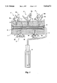
- FIG. 1 is a partially-sectioned front view of the tool with a roller and separate calyx-like or tuft-like decorating elements applied to the body of the roller itself, according to the invention, this embodiment having a rotatable, deformable body, for example, of spongy material;
- FIG. 2 is a partial side view of the tool of FIG. 1, on an enlarged scale
- FIGS. 3, 4, 5, 6 and 7 are plan views of square, rectangular, circular, star-shaped and cross-shaped pieces of fabric or absorbent sheet, respectively, suitable for being inserted radially like calices in the body of the roller after their central regions have been pleated,
- FIG. 8 is a partially-sectioned, partial side view of an embodiment of the roller according to the invention having removable tuft-like decorating elements
- FIG. 9 is a view of FIG. 8 from the left-hand side and on an enlarged scale
- FIG. 10 is a perspective view of a removable tuft-like decorating element and its support, on an enlarged scale
- FIG. 11 is partially-sectioned partial side view of an embodiment of a roller according to the invention having tuft-like decorating elements which are fixed by stapling,
- FIG. 12 is a view of FIG. 11 from the left-hand side
- FIG. 13 is a partial view showing a detail of the tip of a tuft-like decorating element of FIG. 11, sectioned and on an enlarged scale,
- FIG. 14 is a perspective view showing, on an enlarged scale, a tuft-like decorating element which is fixed to the body of the roller by stapling.
- the drawings show a roller body, indicated 1, which, to advantage, is of a spongy or absorbent material, for example, expanded PVC, expanded polyurethane, acrylic, polyamide, or woollen fabric, or the like, with a diameter of from a few centimeters up to about ten centimeters or more, and in the; periphery of which the tips 1a of tuft-like or calyx-like decorating elements 2 are inserted in respective blind holes 3 in order to be fixed therein by gluing; each raft has curled or, in any case, raised edges because an inner region of the flat element from which it is formed has been pleated or squeezed, even tangentially, along at least two lines which, to advantage, intersect; the regular, or possibly indented, outline of each piece 3b of fabric, cloth, hide, or synthetic material, or tape constituting the flat shape of the respective tuft is indicated 3a; the portions which project radially from the surface of the roller in very varied and variously intersecting spatial orientations are indicated 3c;
- the roller is used in the following manner; a base layer of paint is in any case spread on the surface to be decorated and, before it has dried, the body of the roller 1, 15, 21 is urged against the surface and the axis of the roller is moved in a plane substantially parallel to the surface thus squeezing the calyx-like or tuft-like decorating elements 2, 9, 19 against the surface to be decorated in order to cause their edges to roll on the wall without appreciable slippage; this alters the coat of paint producing irregular thicker and thinner portions constituting impressions or marks; a variation of the pressure of the roller against the wall intensifies the contrast between the lighter base colour and the darker regions of the edges of the impressions.
- the calyx-like or tuft-like decorating elements may also be sewn directly to the outer surface of the roller or joined thereto by rivets or nails or even by split pins; as regards the removable connections, these may also be formed, for example, by buttons, so-called press-studs, or even removable connections of another type.
- each tuft-like or calyx-like decorating element may be constituted by two or more concentric layers or by at least two tufts side by side with their tips converging at the periphery of the roller body.
- the decorating elements which may even be staggered, they may be aligned along generatrices of the roller or may be in helical or other convenient arrangements.
Landscapes
- Engineering & Computer Science (AREA)
- Mechanical Engineering (AREA)
- Treatment Of Fiber Materials (AREA)
- Application Of Or Painting With Fluid Materials (AREA)
- Cosmetics (AREA)
- Rolls And Other Rotary Bodies (AREA)
- Massaging Devices (AREA)
- Dry Shavers And Clippers (AREA)
- Manufacture Of Macromolecular Shaped Articles (AREA)
- Vehicle Interior And Exterior Ornaments, Soundproofing, And Insulation (AREA)
- Registering, Tensioning, Guiding Webs, And Rollers Therefor (AREA)
Applications Claiming Priority (3)
| Application Number | Priority Date | Filing Date | Title |
|---|---|---|---|
| ITMO920008A IT1259305B (it) | 1992-01-27 | 1992-01-27 | Rullo decoratore per ottenere effetti chiaroscurali come da tamponatura |
| ITMO92A0008 | 1992-01-27 | ||
| PCT/EP1993/000157 WO1993014879A1 (en) | 1992-01-27 | 1993-01-25 | A decorating roller for producing contrast effects such as those produced with pads |
Publications (1)
| Publication Number | Publication Date |
|---|---|
| US5626672A true US5626672A (en) | 1997-05-06 |
Family
ID=11385114
Family Applications (1)
| Application Number | Title | Priority Date | Filing Date |
|---|---|---|---|
| US08/256,857 Expired - Fee Related US5626672A (en) | 1992-01-27 | 1993-01-25 | Decorating roller for producing contrast effects such as those produced with pads |
Country Status (10)
| Country | Link |
|---|---|
| US (1) | US5626672A (de) |
| EP (1) | EP0681511B1 (de) |
| AT (1) | ATE156390T1 (de) |
| AU (1) | AU3451193A (de) |
| CA (1) | CA2127124A1 (de) |
| DE (2) | DE9313001U1 (de) |
| ES (1) | ES2107652T3 (de) |
| IT (1) | IT1259305B (de) |
| MX (1) | MX9300449A (de) |
| WO (1) | WO1993014879A1 (de) |
Cited By (19)
| Publication number | Priority date | Publication date | Assignee | Title |
|---|---|---|---|---|
| US5857235A (en) * | 1997-06-16 | 1999-01-12 | Morris; Stephen E. | Paint applicator |
| US5885349A (en) * | 1996-02-29 | 1999-03-23 | Giallourakis; Michael A. | Paint pad |
| US6305045B1 (en) | 1999-07-08 | 2001-10-23 | Newell Operating Company | Paint supply and finishing system |
| US6348235B1 (en) | 1999-04-08 | 2002-02-19 | Driveway Magic | Painting apparatus and method |
| USD463135S1 (en) | 2000-10-19 | 2002-09-24 | Susan Goans Driggers | Roller cover |
| US20030126711A1 (en) * | 2002-01-04 | 2003-07-10 | Lev Korenevsky | Paint roller frame with accessories |
| US6641664B1 (en) | 1996-02-29 | 2003-11-04 | Michael A. Giallourakis | Paint pad |
| US20090308309A1 (en) * | 2008-06-13 | 2009-12-17 | Mohamed Abdel Aziz | Flocked applicator and method of making |
| US20150251362A1 (en) * | 2014-03-10 | 2015-09-10 | Siemens Aktiengesellschaft | Method and a mold for manufacturing a component for a wind turbine |
| US10839718B2 (en) | 2014-06-27 | 2020-11-17 | Illinois Tool Works Inc. | System and method of monitoring welding information |
| US10913126B2 (en) | 2014-01-07 | 2021-02-09 | Illinois Tool Works Inc. | Welding software for detection and control of devices and for analysis of data |
| US10964229B2 (en) | 2014-01-07 | 2021-03-30 | Illinois Tool Works Inc. | Feedback from a welding torch of a welding system |
| US11014183B2 (en) * | 2014-08-07 | 2021-05-25 | Illinois Tool Works Inc. | System and method of marking a welding workpiece |
| US11127133B2 (en) | 2014-11-05 | 2021-09-21 | Illinois Tool Works Inc. | System and method of active torch marker control |
| US11127313B2 (en) | 2013-12-03 | 2021-09-21 | Illinois Tool Works Inc. | Systems and methods for a weld training system |
| US11192199B2 (en) | 2014-11-05 | 2021-12-07 | Illinois Tool Works Inc. | System and method for weld-training system |
| US11241754B2 (en) | 2014-01-07 | 2022-02-08 | Illinois Tool Works Inc. | Feedback from a welding torch of a welding system |
| US11482131B2 (en) | 2014-11-05 | 2022-10-25 | Illinois Tool Works Inc. | System and method of reviewing weld data |
| US12233488B2 (en) | 2015-04-02 | 2025-02-25 | Illinois Tool Works Inc. | Systems and methods for tracking weld training arc parameters |
Families Citing this family (4)
| Publication number | Priority date | Publication date | Assignee | Title |
|---|---|---|---|---|
| WO1995025602A1 (en) * | 1994-03-23 | 1995-09-28 | Macri Chemicals S.R.L. | Apparatus for broken pattern decoration |
| NL1001665C2 (nl) * | 1995-11-16 | 1997-05-21 | Coram International B V | Inrichting voor het aanbrengen van verf of dergelijke vloeistof op een oppervlak. |
| US5577291A (en) * | 1996-01-02 | 1996-11-26 | Myers; Micheal J. | Decorative paint roller device |
| US5806130A (en) * | 1997-01-07 | 1998-09-15 | Pascoe; Graciela C. | Decorating tool |
Citations (8)
| Publication number | Priority date | Publication date | Assignee | Title |
|---|---|---|---|---|
| US1003647A (en) * | 1910-11-11 | 1911-09-19 | United Printing Machinery Company | Dusting-roll. |
| GB553522A (en) * | 1942-02-11 | 1943-05-25 | Curtis Albert Riess | An improved stippler |
| GB604630A (en) * | 1945-11-29 | 1948-07-07 | Frank Holden | A new or improved decorating tool or instrument |
| US3536037A (en) * | 1968-01-30 | 1970-10-27 | Du Pont | Anisopanoramic roller |
| US4244074A (en) * | 1978-10-17 | 1981-01-13 | Ppg Industries, Inc. | Pad applicator |
| EP0406514A2 (de) * | 1989-07-05 | 1991-01-09 | Yugen Kaisha Ohta Kogyo | Farbroller und Verfahren, das diesen Roller verwendet |
| US5127123A (en) * | 1987-06-29 | 1992-07-07 | Belanger, Inc. | Rotary cloth roll assembly |
| EP0302662B1 (de) * | 1987-08-05 | 1992-09-30 | Imperial Chemical Industries Plc | Werkzeug zum Streichen |
-
1992
- 1992-01-27 IT ITMO920008A patent/IT1259305B/it active IP Right Grant
-
1993
- 1993-01-25 DE DE9313001U patent/DE9313001U1/de not_active Expired - Lifetime
- 1993-01-25 DE DE69312969T patent/DE69312969T2/de not_active Expired - Fee Related
- 1993-01-25 WO PCT/EP1993/000157 patent/WO1993014879A1/en not_active Ceased
- 1993-01-25 US US08/256,857 patent/US5626672A/en not_active Expired - Fee Related
- 1993-01-25 CA CA002127124A patent/CA2127124A1/en not_active Abandoned
- 1993-01-25 EP EP93903229A patent/EP0681511B1/de not_active Expired - Lifetime
- 1993-01-25 ES ES93903229T patent/ES2107652T3/es not_active Expired - Lifetime
- 1993-01-25 AU AU34511/93A patent/AU3451193A/en not_active Abandoned
- 1993-01-25 AT AT93903229T patent/ATE156390T1/de active
- 1993-01-27 MX MX9300449A patent/MX9300449A/es not_active IP Right Cessation
Patent Citations (8)
| Publication number | Priority date | Publication date | Assignee | Title |
|---|---|---|---|---|
| US1003647A (en) * | 1910-11-11 | 1911-09-19 | United Printing Machinery Company | Dusting-roll. |
| GB553522A (en) * | 1942-02-11 | 1943-05-25 | Curtis Albert Riess | An improved stippler |
| GB604630A (en) * | 1945-11-29 | 1948-07-07 | Frank Holden | A new or improved decorating tool or instrument |
| US3536037A (en) * | 1968-01-30 | 1970-10-27 | Du Pont | Anisopanoramic roller |
| US4244074A (en) * | 1978-10-17 | 1981-01-13 | Ppg Industries, Inc. | Pad applicator |
| US5127123A (en) * | 1987-06-29 | 1992-07-07 | Belanger, Inc. | Rotary cloth roll assembly |
| EP0302662B1 (de) * | 1987-08-05 | 1992-09-30 | Imperial Chemical Industries Plc | Werkzeug zum Streichen |
| EP0406514A2 (de) * | 1989-07-05 | 1991-01-09 | Yugen Kaisha Ohta Kogyo | Farbroller und Verfahren, das diesen Roller verwendet |
Cited By (23)
| Publication number | Priority date | Publication date | Assignee | Title |
|---|---|---|---|---|
| US6641664B1 (en) | 1996-02-29 | 2003-11-04 | Michael A. Giallourakis | Paint pad |
| US5885349A (en) * | 1996-02-29 | 1999-03-23 | Giallourakis; Michael A. | Paint pad |
| US5857235A (en) * | 1997-06-16 | 1999-01-12 | Morris; Stephen E. | Paint applicator |
| US6348235B1 (en) | 1999-04-08 | 2002-02-19 | Driveway Magic | Painting apparatus and method |
| US6305045B1 (en) | 1999-07-08 | 2001-10-23 | Newell Operating Company | Paint supply and finishing system |
| USD463135S1 (en) | 2000-10-19 | 2002-09-24 | Susan Goans Driggers | Roller cover |
| US20030126711A1 (en) * | 2002-01-04 | 2003-07-10 | Lev Korenevsky | Paint roller frame with accessories |
| US20090308309A1 (en) * | 2008-06-13 | 2009-12-17 | Mohamed Abdel Aziz | Flocked applicator and method of making |
| US11127313B2 (en) | 2013-12-03 | 2021-09-21 | Illinois Tool Works Inc. | Systems and methods for a weld training system |
| US10964229B2 (en) | 2014-01-07 | 2021-03-30 | Illinois Tool Works Inc. | Feedback from a welding torch of a welding system |
| US11676509B2 (en) | 2014-01-07 | 2023-06-13 | Illinois Tool Works Inc. | Feedback from a welding torch of a welding system |
| US11241754B2 (en) | 2014-01-07 | 2022-02-08 | Illinois Tool Works Inc. | Feedback from a welding torch of a welding system |
| US10913126B2 (en) | 2014-01-07 | 2021-02-09 | Illinois Tool Works Inc. | Welding software for detection and control of devices and for analysis of data |
| US10730251B2 (en) | 2014-03-10 | 2020-08-04 | Siemens Gamesa Renewable Energy A/S | Mold for manufacturing a component for a wind turbine |
| US10086570B2 (en) * | 2014-03-10 | 2018-10-02 | Siemens Aktiengesellschaft | Method and a mold for manufacturing a component for a wind turbine |
| US20150251362A1 (en) * | 2014-03-10 | 2015-09-10 | Siemens Aktiengesellschaft | Method and a mold for manufacturing a component for a wind turbine |
| US10839718B2 (en) | 2014-06-27 | 2020-11-17 | Illinois Tool Works Inc. | System and method of monitoring welding information |
| US12131663B2 (en) | 2014-06-27 | 2024-10-29 | Illinois Tool Works Inc. | System and method of monitoring welding information |
| US11014183B2 (en) * | 2014-08-07 | 2021-05-25 | Illinois Tool Works Inc. | System and method of marking a welding workpiece |
| US11127133B2 (en) | 2014-11-05 | 2021-09-21 | Illinois Tool Works Inc. | System and method of active torch marker control |
| US11192199B2 (en) | 2014-11-05 | 2021-12-07 | Illinois Tool Works Inc. | System and method for weld-training system |
| US11482131B2 (en) | 2014-11-05 | 2022-10-25 | Illinois Tool Works Inc. | System and method of reviewing weld data |
| US12233488B2 (en) | 2015-04-02 | 2025-02-25 | Illinois Tool Works Inc. | Systems and methods for tracking weld training arc parameters |
Also Published As
| Publication number | Publication date |
|---|---|
| HK1000764A1 (en) | 1998-04-24 |
| MX9300449A (es) | 1994-07-29 |
| ITMO920008A0 (it) | 1992-01-27 |
| EP0681511B1 (de) | 1997-08-06 |
| AU3451193A (en) | 1993-09-01 |
| IT1259305B (it) | 1996-03-11 |
| ATE156390T1 (de) | 1997-08-15 |
| DE9313001U1 (de) | 1993-10-14 |
| WO1993014879A1 (en) | 1993-08-05 |
| ITMO920008A1 (it) | 1993-07-27 |
| ES2107652T3 (es) | 1997-12-01 |
| DE69312969T2 (de) | 1997-12-18 |
| DE69312969D1 (de) | 1997-09-11 |
| EP0681511A1 (de) | 1995-11-15 |
| CA2127124A1 (en) | 1993-08-05 |
Similar Documents
| Publication | Publication Date | Title |
|---|---|---|
| US5626672A (en) | Decorating roller for producing contrast effects such as those produced with pads | |
| US5693141A (en) | Special effect paint roller | |
| US2835259A (en) | Artificial eyelashes | |
| US5983437A (en) | Bifurcated paint roller and painting method | |
| US5246775A (en) | Self-sticking drywall tape | |
| US4403000A (en) | Method of forming a cohesive display object | |
| US6863076B2 (en) | Foil for use in hair coloring, and method of use | |
| US6330731B1 (en) | Faux finish applicator | |
| EP0979684B1 (de) | System zum Farbauftrag | |
| US6641664B1 (en) | Paint pad | |
| HK1000764B (en) | A decorating roller for producing contrast effects such as those produced with pads | |
| US20030037868A1 (en) | Method and apparatus for applying designs to surfaces | |
| US5806130A (en) | Decorating tool | |
| US6284318B1 (en) | Painting method with long-napped wool covered rollers | |
| US4673599A (en) | Synthetic fur garland and method of making same | |
| US6284075B1 (en) | Device and method for applying a decorative material | |
| US6101658A (en) | Liquid coating applicator having spaced applicating mediums | |
| US3474482A (en) | Paint roller with coating thickness indicator and method for forming said indicator | |
| EP4166244B1 (de) | Lackierverfahren | |
| JPS6034429B2 (ja) | 電気植毛加工方法 | |
| US4876138A (en) | Synthetic leather-like material | |
| WO2000020126A9 (en) | Decorative surface treatment apparatus and method | |
| EP4335553B1 (de) | Lackiervorrichtung | |
| HK40091418B (en) | Painting method | |
| HK40091418A (en) | Painting method |
Legal Events
| Date | Code | Title | Description |
|---|---|---|---|
| AS | Assignment |
Owner name: SPETRA S.R.L., ITALY Free format text: ASSIGNMENT OF ASSIGNORS INTEREST;ASSIGNOR:ROSSETTI, EDOARDO;REEL/FRAME:007284/0884 Effective date: 19940608 |
|
| REMI | Maintenance fee reminder mailed | ||
| FEPP | Fee payment procedure |
Free format text: PAYOR NUMBER ASSIGNED (ORIGINAL EVENT CODE: ASPN); ENTITY STATUS OF PATENT OWNER: SMALL ENTITY |
|
| LAPS | Lapse for failure to pay maintenance fees | ||
| FP | Lapsed due to failure to pay maintenance fee |
Effective date: 20010506 |
|
| STCH | Information on status: patent discontinuation |
Free format text: PATENT EXPIRED DUE TO NONPAYMENT OF MAINTENANCE FEES UNDER 37 CFR 1.362 |