US5647688A - Paving machine with extended telescoping members - Google Patents
Paving machine with extended telescoping members Download PDFInfo
- Publication number
- US5647688A US5647688A US08/570,760 US57076095A US5647688A US 5647688 A US5647688 A US 5647688A US 57076095 A US57076095 A US 57076095A US 5647688 A US5647688 A US 5647688A
- Authority
- US
- United States
- Prior art keywords
- members
- telescoping
- male
- frame
- female
- Prior art date
- Legal status (The legal status is an assumption and is not a legal conclusion. Google has not performed a legal analysis and makes no representation as to the accuracy of the status listed.)
- Expired - Lifetime
Links
- 239000004606 Fillers/Extenders Substances 0.000 claims abstract description 52
- 230000000694 effects Effects 0.000 claims description 3
- 238000003780 insertion Methods 0.000 abstract description 15
- 230000037431 insertion Effects 0.000 abstract description 15
- 238000000034 method Methods 0.000 description 5
- 238000009434 installation Methods 0.000 description 3
- 230000013011 mating Effects 0.000 description 2
- 230000007935 neutral effect Effects 0.000 description 2
- 230000003014 reinforcing effect Effects 0.000 description 2
- 230000003190 augmentative effect Effects 0.000 description 1
- 230000006835 compression Effects 0.000 description 1
- 238000007906 compression Methods 0.000 description 1
- 238000010276 construction Methods 0.000 description 1
- 230000008602 contraction Effects 0.000 description 1
- 238000007373 indentation Methods 0.000 description 1
- 239000007788 liquid Substances 0.000 description 1
- 239000000463 material Substances 0.000 description 1
- 230000000149 penetrating effect Effects 0.000 description 1
- 238000009966 trimming Methods 0.000 description 1
- 238000005303 weighing Methods 0.000 description 1
Images




Classifications
-
- E—FIXED CONSTRUCTIONS
- E01—CONSTRUCTION OF ROADS, RAILWAYS, OR BRIDGES
- E01C—CONSTRUCTION OF, OR SURFACES FOR, ROADS, SPORTS GROUNDS, OR THE LIKE; MACHINES OR AUXILIARY TOOLS FOR CONSTRUCTION OR REPAIR
- E01C19/00—Machines, tools or auxiliary devices for preparing or distributing paving materials, for working the placed materials, or for forming, consolidating, or finishing the paving
- E01C19/22—Machines, tools or auxiliary devices for preparing or distributing paving materials, for working the placed materials, or for forming, consolidating, or finishing the paving for consolidating or finishing laid-down unset materials
- E01C19/30—Tamping or vibrating apparatus other than rollers ; Devices for ramming individual paving elements
- E01C19/34—Power-driven rammers or tampers, e.g. air-hammer impacted shoes for ramming stone-sett paving; Hand-actuated ramming or tamping machines, e.g. tampers with manually hoisted dropping weight
- E01C19/40—Power-driven rammers or tampers, e.g. air-hammer impacted shoes for ramming stone-sett paving; Hand-actuated ramming or tamping machines, e.g. tampers with manually hoisted dropping weight adapted to impart a smooth finish to the paving, e.g. tamping or vibrating finishers
-
- E—FIXED CONSTRUCTIONS
- E01—CONSTRUCTION OF ROADS, RAILWAYS, OR BRIDGES
- E01C—CONSTRUCTION OF, OR SURFACES FOR, ROADS, SPORTS GROUNDS, OR THE LIKE; MACHINES OR AUXILIARY TOOLS FOR CONSTRUCTION OR REPAIR
- E01C2301/00—Machine characteristics, parts or accessories not otherwise provided for
- E01C2301/14—Extendable screeds
- E01C2301/16—Laterally slidable screeds
-
- E—FIXED CONSTRUCTIONS
- E01—CONSTRUCTION OF ROADS, RAILWAYS, OR BRIDGES
- E01C—CONSTRUCTION OF, OR SURFACES FOR, ROADS, SPORTS GROUNDS, OR THE LIKE; MACHINES OR AUXILIARY TOOLS FOR CONSTRUCTION OR REPAIR
- E01C2301/00—Machine characteristics, parts or accessories not otherwise provided for
- E01C2301/14—Extendable screeds
- E01C2301/16—Laterally slidable screeds
- E01C2301/18—Laterally slidable screeds the whole machine being laterally slidable
Definitions
- This invention relates to concrete pavers of the slipform variety. More particularly, a concrete paver is disclosed in which telescoping frame members extending across the paver are provided with extension members. These extension members enable the paver to expand to paving widths beyond that presently achieved by conventional telescoping members. Further, the present disclosure does away with the necessity of the installation of a fixed frame extension members. As a result, this invention also substantially reduces machine preparation time for paving at differing machine widths.
- Concrete slipform pavers are known. Specifically, such pavers include a “tractor” and a “paving kit”.
- most concrete slipform pavers include a tractor which is comprised of a rectilinear frame which straddles the concrete roadway or runway while it is paved. This frame is propelled and supported on either end by side bolsters and crawler track(s). The frame supports a diesel engine driven hydraulic power unit which supplies power to the tractor and paving kit.
- the paving kit is typically suspended below the tractor frame by mechanical means.
- the paving kit takes its hydraulic power from the power unit on the tractor.
- the tractor and paving kit comprising the slipform pass over the concrete placed in its path in a relatively even and level mass that can be conveniently paved.
- the tractor attached paving kit spreads the concrete dumped in the path of the paver, levels and vibrates it into a semi-liquid state, then confines and finishes the concrete into a slab with an upwardly exposed and finished surface.
- Sideforms mounted to the side of the slipform kit confine the sides of the slab during the paving process.
- the tractor typically has either two or four crawler tracks supporting and propelling the frame and attached paving kit.
- Other kits can be attached to these tractors such as kits for conveying and spreading concrete and trimming and spreading base materials.
- paving kit used for slipform paving.
- the tractor frame is known to telescope itself normal to the direction of the paving movement. This telescoping normal to the direction of the paving movement enables the tractor frame to span different widths of pavements within the limits of the telescopic extensions. Once these telescopic extensions limits are reached, a fixed frame extension can be added to one or both sides of the telescopic frame for further extension. Despite the telescopic ability of the frame, the process is still a relatively complex and time consuming operation. Adding a fixed frame extension(s) significantly increases the complexity and difficulty of the frame width change.
- this addition requires that the side bolster and crawler(s) on at least one side of the machine be removed, the fixed frame extension inserted, and the side bolster and crawlers re-attached. Hydraulic and electrical lines must also be disconnected then reconnected. This is not a trivial operation.
- the frame section and side bolster/-crawlers are heavy members. They must be separately manipulated into place --usually by cranes and their attendant crews. Cranes have scheduling problems, are big, heavy, dangerous, and slow.
- a conventional telescoping frame on a paving tractor is provided with fixed frame extension members for insertion to and attachment with a telescoping frame member.
- the conventional telescoping frame includes paired forward and paired rear side-by-side female tube members.
- Each forward and rear tube member conventionally acts for the telescoping support of male extension members which attach directly to the side bolster, which in turn attaches to the hydraulic jacking columns and crawlers.
- the male extension members co-acting with clamps acting through the female tube members provide for both movement of the point of crawler support and expansion of the paving width of the tractor frame.
- extenders are added for attachment to the supported end of the male extension members interior of the female telescoping members.
- the male telescoping members are expanded to register their ends interior of the female telescoping members to attachment access ports in the female telescoping member.
- the extenders are inserted, supported, and registered at complimentary attachment apertures with attachment to the male telescoping members taking place. Once attachment has occurred, further extension of the male telescoping members occurs.
- a simple system of pinned cross-bracing reinforces the extended frame with relatively light bracing members.
- the male telescoping member includes single male flange having paired upper and lower pin apertures.
- extenders include paired female flange members with mating upper pin aperture and lower pin apertures.
- locator pin within the extender.
- the male telescoping member is extended by crawler movement until registration of the paired upper and lower pin apertures occurs at elongate upper and lower apertures in the box beams. Thereafter, extender insertion occurs with the single male flange penetrating to the locator pin first at the gathering surfaces and then at the locator aperture. With full insertion of the extender, the end of the extender is raised or lowered to center either and upper or lower pin. Once the upper or lower pin is centered, pin insertion occurs. Assuming registration of at least one pin and the locator pin at the locator aperture, insertion of the remaining pin readily follows. Rapid extender connection results.
- FIG. 1A is a perspective view of a concrete paver of this invention in conventional operation
- FIG. 1B is a perspective view of a concrete paver illustrating the crawler tracks turned 90° from the paving disposition illustrated in FIG. 1A and with the telescoping members in an orientation where the extending members may be inserted into the paver female telescoping tractor frame to increase the paving width;
- FIG. 1C is a detail of the insertion of the extending members--it being understood that light lifting equipment (not shown) causes the required insert of the extender;
- FIG. 2 is a perspective view that illustrates one side of the paver extended to the increased width for paving a wider slab, the other side of the paver not being shown and shows the light bracing members in position;
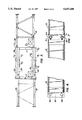
- FIG. 3 is a plan schematic of the frame illustrating the principle of extension insertion for expanding the frame, the paver side bolsters not being shown;
- FIG. 4A is a side elevation of the female telescoping member and a plan and elevation of the extender member illustrating apertures for the installation of pins to enable connection interior of the female telescoping tube of the extenders to the male member;
- FIG. 4B is an elevation of the forward box beam of the paver frame illustrating apertures for insertion of pins to effect fastening of the extenders with the hidden lines showing apertures located on the inner female telescoping tube;
- FIG. 5 is a plan schematic of the frame illustrating offset of the paver frame in expansion for positioning a reinforcing bar inserter at a position where interference with the frame member does not occur;
- FIG. 6 is a detail illustrating the connecting end of the extender to the male telescoping member
- FIG. 7 is a detail of the male telescoping member connected to an extender, and applicable pins inserted through the female telescoping member, it being noted that line up pin holes may be required in the male telescopic member and extender connection for ease of pin hole line up;
- FIG. 8 is a partial plan view of the frame illustrating the case where the extenders are attached and the frame is contacted to minimum dimension;
- FIG. 9A and 9B are respective plan view and side elevations of the male telescoping member and extender separated from one another so that the gathering feature of this invention can be understood;
- FIG. 10 is a side elevation of the single male member attached to the male telescoping member.
- FIGS. 11A and 11B are respective side elevation section at the box beam illustrating the juxtaposition of the male telescoping member and extender interior of the box beam and a detail of the recess and securing leaf for the inserted fastener pins.
- FIG. 1A illustrates paver P proceeding in paving direction 15 for paving roadway or runway R.
- Paver P includes tractor frame F and paving kit K. Since the invention herein relates to the configuration of tractor frame F, paving kit K will be briefly discussed. In the description here, it will be assumed that conventional paving kit may be removed or attached from tractor frame F for the purposes of transport or to add other attachments without further discussion.
- Paving kit K is conventional and includes spreader plow 18.
- Spreader plow 18 functions to spread concrete placed in paving direction 15 on what is to become roadway or runway R. There follows metering gate, vibrators, slipform pan 22 and trailing pan 24. It will be understood that paving kit K can be augmented with all sorts of accessories. Reinforcing bar inserters, tamper bars, side bar inserters and the like are typically added or taken off the machine as the job requires.
- the width of the paving kit K is varied with extensions like the tractor frame F as the particular width of the job specifies.
- Such paving kit extensions come in all matter of widths. It is common to have one foot, two foot, three foot, five foot, and six foot extensions. In the conventional placement of these sections, the telescopic tractor frame is first expanded, and the requisite number and length of paving kit extensions installed. Since this process is conventional, it will not be further discussed herein.
- a paver can be simply stated for purposes of this description.
- a system of grade level reference wires W are strung adjacent and parallel to the roadway or runway grade being constructed.
- Sensors 26 with wire feelers, one located at each corner of the machine attached to the frame follow grade level reference wires W.
- Leveling sensors (not shown) on the frame independently adjusts the height of the frame relative to each of crawlers T 1 -T 4 through hydraulic cylinder C 1 -C 4 at each corner of the frame.
- the paving kit suspended from the frame thus is continually adjusted to maintain a preset elevation disposition relative to the wires as paving occurs.
- Frame F can be best understood with a first reference to FIG. 1A.
- Frame F includes side relatively telescoping members S. These respective side relatively telescoping members S are fully set forth and described in Guntert et al U.S. patent application Ser. No. 08/450,242, filed May. 25, 1995 entitled FOUR TRACK PAVING MACHINE WITH TELESCOPING TRANSPORT COMPRESSION IN DIRECTION 0F PAVING MACHINE TRAVEL. An abbreviated description of the function of these side relatively telescoping members S will suffice.
- the rectilinear frame includes four crawlers T 1 -T 4 , one at each corner of the frame. Each crawlers T 1 -T 4 is directly supported on its own hydraulic cylinder C 1 -C 4 and mounted for pivotal movement about the axis of the hydraulic cylinder.
- the frame telescopes at side relatively telescoping side bolster members S between the leading and trailing crawlers at the sides of the machine. When expanded, the paving machine has the full forward and rear dimension required for paving.
- the paving machine When contracted, the paving machine has a profile allowing convenient transport with the crawlers rotated 90° or normal to the direction of travel to power the frame widening. Full details of this function of the machine can be realized by consulting the above reference patent application which is incorporated by reference into this patent application.
- Conventional four track paver side bolsters with pivoting arms can also be used with the present application. It is envisioned that the present application can also be used with two track paver provided external hydraulic cylinders are utilized to provide the power to telescope in the absence of four crawler tracks and the ability of turning the four crawlers 90° or normal to the direction of paving to power the frame widening.
- the present application relates to the side to side paving expansion of paver P. This being the case, attention will now be directed to FIG. 3.
- This figure is advantageous because it focuses on the paving width extension of the paver telescopic tractor frame and does not show the appurtenant apparatus.
- Rectilinear tractor frame F includes forward box Beam B F and rear box beam B R .
- Each forward box beam B F and each rear box beam B R defines leading interior female compartment 28 and trailing interior female compartment 30.
- side relatively telescoping members S and forward box beam B F and rear box beam B R define a rectilinear tractor frame F.
- forward box beam B F and rear box beam B R each define forward female telescoping member F F at leading interior female compartment 28 and rear female telescoping member F R at trailing interior female compartment 30.
- male telescoping members be received into the respective female telescoping members. This being the case, right forward male telescoping member 32 is received in forward female telescoping member F F of forward box beam B F . Similarly, left forward male telescoping member 34 is received in rear female telescoping member F R of forward box beam B F .
- the trailing section of the frame is identically constructed.
- Right trailing male telescoping member 36 is supported in forward female telescoping member F F of rear box beam B R .
- left trailing male telescoping member 38 is supported in rear female telescoping member F R of rear box beam B R .
- Forward box beam B F and rear box beam B R are typically a nominal 12 feet in length. Respective right forward male telescoping member 32, left forward male telescoping member 34, right trailing male telescoping member 36, and left trailing male telescoping member 38 are also 12 feet in length. This enables the leading and trailing male telescoping members to be entirely received within forward box beam B F and rear box beam B R . It can therefore be quickly understood by the reader that the present machine has a capability of paving over a 12 foot span to match the minimum paving width generally paved in the United States. Even though the tractor frame might be limited to a minimum width of 12', when the telescopic frame is fully contracted, the paving kit may be arranged in a paving width less than 12'.
- crawlers T 1 -T 4 are rotated 90° by respective turning cylinders 40, it can be seen that powering of crawlers T 1 -T 4 can move to extend the respective male telescoping members 32, 34, 36, and 38.
- the respective male telescoping members 32, 34, 36, and 38 would all be extended in the range of six to six and one half feet. This would extend the paver tractor frame from 12 foot to a maximum range of a 25 foot span. In the prior art, this is the maximum paving width extension that such a paver would allow.
- male telescoping members 32, 34, 36, and 38 are in cantilever support when extended from the respective forward box beam B F and rear box beam B R . Further, the paver is heavy, weighing in the order of 75,000 pounds or more. It is therefore to be understood that extension of male telescoping members 32, 34, 36, and 38 substantially beyond a six foot extension is not prudent. Thus a certain minimum length of male telescoping member must remain engaged in the female box beam frame section to maintain the structural integrity of the tractor frame.
- the only way the paver telescopic tractor frame could be extended beyond the maximum telescopic ability of 25' was to unbolt and hydraulically disconnect the cylinders C 1 -C 4 and crawler tracks T 1 -T 4 from each corner of the machine and add a fixed frame extension to the ends of the male telescopic members 32, 34, 36, and 38 and the cylinders C 1 -C 4 .
- extenders E 1 -E 4 can now be discussed. This may be most conveniently done by considering the disposition of tractor frame F as illustrated in FIG. 3 and thereafter discussing the extension of the frame as illustrated in FIG. 5.
- tractor frame F Before insertion of extenders E 1 -E 4 , it is required that tractor frame F be expanded to the approximately 25 foot span illustrated in FIG. 3. This defines clearance required for receipt of extenders E 1 -E 4 in two discrete aspects.
- the respective forward female telescoping member F F and rear female telescoping member F R of forward box beam B F and rear box beam B R are open on the ends for receipt of extenders E 1 -E 4 .
- hydraulic cylinders C 1 -C 4 and crawlers T 1 -T 4 are sufficiently moved away from forward box beam B F and rear box beam B R so as to define clearance for insertion of extenders E 1 -E 4 .
- extenders E 1 -E 4 are relatively simple matter that can be handled by the on-site operating crew of the paver. Specifically, by utilizing a fork lift, boom truck or similar lifting apparatus, each of extenders E 1 -E 4 can be individually inserted. At the same time, detachment of heavy hydraulic cylinders C 1 -C 4 and crawlers T 1 -T 4 is not required.
- right forward male telescoping member 32 is illustrated without attachment of either hydraulic cylinder or crawler. It defines single male connector plate 42 at its end opposite from where the hydraulic cylinder and crawler is attached. Single male connector plate 42 is bored by upper pin aperture 44 and lower pin aperture 46.
- extender E 1 The construction of extender E 1 is analogous. It includes paired female connector plate members 52 which are in turn bored by upper pin aperture 54 and lower pin aperture 56.
- forward box beam B F and rear box beam B R The detail of forward box beam B F in FIG. 4B provides elongate upper aperture 64 and elongate lower aperture 66 in forward box beam B F .
- paver P expansion and contraction of paver P can occur through crawlers T 1 -T 4 .
- the paver P is designed so the crawler tracks on each side of the machine can be controlled together as a pair. This provides the power for driving the telescoping movement.
- conventional external hydraulic cylinders as used in the prior art, connected between the male and female telescopic members, can be used to power the telescopic movement.
- tractor frame F As illustrated in FIG. 5, paver P is expanded to a maximum design paving width of 34 feet. Normally, such expansion will be symmetrical; each of the male telescoping members 32, 34, 36, and 38 will extend the same distance. Since this is easily comprehended, we illustrate the case where eccentric expansion has occurred. A word of explanation of the need for eccentric expansion can be helpful.
- paver P frequently includes installed accessories such as bar inserters, side bar inserters, and other accessories as the vagaries of any job may require.
- the transverse spacing of such accessories may interfere with placement of the major structural members of tractor frame F such as side relatively telescoping members S. This being the case, eccentric expansion such as that illustrated in FIG. 5 can act to register attached accessories to their required location.
- extenders E 2 and E 4 protrude partially from forward box beam B F and rear box beam B R , respectively.
- extenders E 1 and E 3 do not protrude at all from rear box beam B F and rear box beam B R , respectively. This gives the disclosed apparatus a flexibility of dimension that is highly practicable.
- cross bracing of paver P will be desired--if not required.
- FIG. 2 such cross bracing is illustrated.
- Diagonal cross brace 68 and normal cross brace 70 can be used with conventional fastening as by bolts or pins occurring at the distal ends of the braces 68, 70 to male telescoping members 32, 34, 36, and 38.
- one or both of the distal ends of the cross bracing may include a screw adjustable attachment bracket so that the length of the brace does not have to be exact.
- the male telescopic members may be contracted beyond the ends of the female tubes by approximately three feet on a side.
- the resulting range of telescopic ability is 17'6" to 34', or eight and one quarter feet side.
- tractor of this invention includes at least two crawler tracks with one crawler on either side of the paver.
- a tractor having four crawler tracks is included in this definition.
- FIGS. 9A, 9B, 10, 11A and 11B the now preferred interconnection between the extender and male telescoping member is illustrated in FIGS. 9A, 9B, 10, 11A and 11B.
- left forward male telescoping member 34 and extender E 1 is illustrated.
- paired female flange members 52 are provided with locator pin L p .
- Locator pin L p is centered on the neutral axis of extenders E 1 .
- left forward male telescoping member 34 at single male flange 42 has locator aperture L A .
- Locator aperture L A like locator pin L p is centered on the neutral axis of left forward male telescoping member 34.
- Locator aperture L A includes gathering surfaces G S flaring out from locator aperture L A . These respective gathering surfaces G S cause left forward male telescoping member 34 and extenders E 1 to come into registration as illustrated in FIG. 11A.
- the respective male telescoping members such as left forward male telescoping member 34 are moved outward until upper pin aperture 44 and lower pin aperture 46 register within respective elongate upper aperture 64 and elongate lower aperture 66.
- the extenders such as extenders E 1 is typically picked by lifting apparatus central of the extender and inserted to forward box beam B F , Insertion continues until locator aperture L A centers on locator pin L p . Once centering occurs, the distal end of extenders E 1 is moved up and down until centering of pins N in either the upper or lower position can occur.
- pins N be secured in such a manner that they do not interfere with the box beams such as forward box beam B F .
- single male flange 42 is provided with recessed pin platform 74.
- pin N has attached fastening leaf 78 through which bolt 80 threads to fastening tap hole 76. Connection of pins N results with recessing of the pin so that interference with the respective box beams, such as forward box beam B F , does not occur.
Landscapes
- Engineering & Computer Science (AREA)
- Architecture (AREA)
- Civil Engineering (AREA)
- Structural Engineering (AREA)
- Road Paving Machines (AREA)
- Body Structure For Vehicles (AREA)
- Road Paving Structures (AREA)
Priority Applications (6)
| Application Number | Priority Date | Filing Date | Title |
|---|---|---|---|
| US08/570,760 US5647688A (en) | 1995-07-20 | 1995-12-12 | Paving machine with extended telescoping members |
| EP96923448A EP0839230B1 (de) | 1995-07-20 | 1996-06-25 | Strassenfertiger mit verlängerbaren auslegern |
| AU63956/96A AU6395696A (en) | 1995-07-20 | 1996-06-25 | Paving machine with extended telescoping members |
| PCT/US1996/010908 WO1997004176A1 (en) | 1995-07-20 | 1996-06-25 | Paving machine with extended telescoping members |
| AT96923448T ATE248952T1 (de) | 1995-07-20 | 1996-06-25 | Strassenfertiger mit verlängerbaren auslegern |
| DE69629817T DE69629817T2 (de) | 1995-07-20 | 1996-06-25 | Strassenfertiger mit verlängerbaren auslegern |
Applications Claiming Priority (2)
| Application Number | Priority Date | Filing Date | Title |
|---|---|---|---|
| US08/504,858 US5615972A (en) | 1995-07-20 | 1995-07-20 | Paving machine with extended telescoping members |
| US08/570,760 US5647688A (en) | 1995-07-20 | 1995-12-12 | Paving machine with extended telescoping members |
Related Parent Applications (1)
| Application Number | Title | Priority Date | Filing Date |
|---|---|---|---|
| US08/504,858 Continuation-In-Part US5615972A (en) | 1995-07-20 | 1995-07-20 | Paving machine with extended telescoping members |
Publications (1)
| Publication Number | Publication Date |
|---|---|
| US5647688A true US5647688A (en) | 1997-07-15 |
Family
ID=27054961
Family Applications (1)
| Application Number | Title | Priority Date | Filing Date |
|---|---|---|---|
| US08/570,760 Expired - Lifetime US5647688A (en) | 1995-07-20 | 1995-12-12 | Paving machine with extended telescoping members |
Country Status (6)
| Country | Link |
|---|---|
| US (1) | US5647688A (de) |
| EP (1) | EP0839230B1 (de) |
| AT (1) | ATE248952T1 (de) |
| AU (1) | AU6395696A (de) |
| DE (1) | DE69629817T2 (de) |
| WO (1) | WO1997004176A1 (de) |
Cited By (20)
| Publication number | Priority date | Publication date | Assignee | Title |
|---|---|---|---|---|
| US6176643B1 (en) | 1999-10-01 | 2001-01-23 | Guntert & Zimmerman Const. Div. | Detachable dowel bar inserter kit for portable slip form paver |
| WO2001025559A3 (en) * | 1999-10-01 | 2001-10-04 | Guntert & Zimmerman Const Div | Dowel bar inserter kit having chain feeder |
| US6390727B1 (en) | 1999-10-01 | 2002-05-21 | Guntert & Zimmerman Const. Div., Inc. | Dowel bar inserter kit having chain feeder |
| EP1213389A1 (de) * | 1998-03-30 | 2002-06-12 | WIRTGEN GmbH | Gleitschalungsfertiger |
| US6422785B1 (en) | 1999-08-06 | 2002-07-23 | Rexcon-Division Of Rose Industries, Inc. | Track belt placer for placing construction materials and method for placing construction materials |
| US6481924B1 (en) * | 1999-11-26 | 2002-11-19 | Wirtgen Gmbh | Slip-form paver |
| US6551021B2 (en) * | 2001-02-07 | 2003-04-22 | Blaw-Knox Construction Equipment Corporation | Screed plate interlock |
| US6582152B2 (en) | 2000-05-11 | 2003-06-24 | Leone Construction Company | Zero clearance variable width concrete paving machine |
| US7029072B1 (en) | 2002-03-11 | 2006-04-18 | Wirtgen America, Inc. | Modified rumble strip cutter |
| US20100266339A1 (en) * | 2009-04-16 | 2010-10-21 | Guntert & Zimmerman Const. Div., Inc. | Slipform Paving Machine With Adjustable Length Paving Kit |
| US20110194898A1 (en) * | 2010-02-09 | 2011-08-11 | Guntert & Zimmerman Const. Div., Inc. | Slipform Paving Machine With Adjustable Length Tractor Frame |
| CN103993543A (zh) * | 2014-04-30 | 2014-08-20 | 陈建军 | H型四履带滑模摊铺机 |
| CN103993551A (zh) * | 2014-04-30 | 2014-08-20 | 陈建军 | Y型三履带滑移一体机 |
| US8967908B1 (en) | 2013-08-26 | 2015-03-03 | Wirtgen Gmbh | Slipform paver, as well as method for adjusting the width of a mold device |
| US9033619B2 (en) | 2012-12-14 | 2015-05-19 | John Riggle, JR. | Trench shoring apparatuses |
| CN105908601A (zh) * | 2016-06-12 | 2016-08-31 | 天津康远工程机械有限公司 | 具有找平功能的摊铺装置 |
| US9903076B2 (en) | 2016-04-14 | 2018-02-27 | Dan Mohr | Paver extension bracket device |
| US11162233B2 (en) | 2019-12-05 | 2021-11-02 | Wirtgen Gmbh | Adjustable width mold |
| US11339541B2 (en) | 2019-12-05 | 2022-05-24 | Wirtgen Gmbh | Adjustable width mold |
| US12516480B2 (en) | 2022-03-22 | 2026-01-06 | Wirtgen Gmbh | Slipform paver with suspended adjustable width mold |
Families Citing this family (1)
| Publication number | Priority date | Publication date | Assignee | Title |
|---|---|---|---|---|
| DE10128564B4 (de) | 2001-06-13 | 2005-10-27 | Wirtgen Gmbh | Gleitschalungsfertiger |
Citations (2)
| Publication number | Priority date | Publication date | Assignee | Title |
|---|---|---|---|---|
| US3970405A (en) * | 1974-05-03 | 1976-07-20 | Cmi Corporation | Slipform paving apparatus |
| US4789266A (en) * | 1987-11-27 | 1988-12-06 | Power Curbers, Inc. | Self-propelled construction apparatus |
-
1995
- 1995-12-12 US US08/570,760 patent/US5647688A/en not_active Expired - Lifetime
-
1996
- 1996-06-25 DE DE69629817T patent/DE69629817T2/de not_active Expired - Lifetime
- 1996-06-25 AU AU63956/96A patent/AU6395696A/en not_active Abandoned
- 1996-06-25 WO PCT/US1996/010908 patent/WO1997004176A1/en not_active Ceased
- 1996-06-25 AT AT96923448T patent/ATE248952T1/de not_active IP Right Cessation
- 1996-06-25 EP EP96923448A patent/EP0839230B1/de not_active Expired - Lifetime
Patent Citations (2)
| Publication number | Priority date | Publication date | Assignee | Title |
|---|---|---|---|---|
| US3970405A (en) * | 1974-05-03 | 1976-07-20 | Cmi Corporation | Slipform paving apparatus |
| US4789266A (en) * | 1987-11-27 | 1988-12-06 | Power Curbers, Inc. | Self-propelled construction apparatus |
Cited By (27)
| Publication number | Priority date | Publication date | Assignee | Title |
|---|---|---|---|---|
| EP1213389A1 (de) * | 1998-03-30 | 2002-06-12 | WIRTGEN GmbH | Gleitschalungsfertiger |
| US6471442B1 (en) * | 1998-03-30 | 2002-10-29 | Wirtgen Gmbh | Slip form paver |
| US6422785B1 (en) | 1999-08-06 | 2002-07-23 | Rexcon-Division Of Rose Industries, Inc. | Track belt placer for placing construction materials and method for placing construction materials |
| US6176643B1 (en) | 1999-10-01 | 2001-01-23 | Guntert & Zimmerman Const. Div. | Detachable dowel bar inserter kit for portable slip form paver |
| WO2001025559A3 (en) * | 1999-10-01 | 2001-10-04 | Guntert & Zimmerman Const Div | Dowel bar inserter kit having chain feeder |
| US6390727B1 (en) | 1999-10-01 | 2002-05-21 | Guntert & Zimmerman Const. Div., Inc. | Dowel bar inserter kit having chain feeder |
| US6390726B1 (en) | 1999-10-01 | 2002-05-21 | Guntert & Zimmerman Const. Div. | Dowel bar inserter kit having chain feeder |
| US6579037B2 (en) | 1999-10-01 | 2003-06-17 | Guntert & Zimmerman Const. Div. | Dowel bar inserter kit having chain feeder |
| US6481924B1 (en) * | 1999-11-26 | 2002-11-19 | Wirtgen Gmbh | Slip-form paver |
| US6582152B2 (en) | 2000-05-11 | 2003-06-24 | Leone Construction Company | Zero clearance variable width concrete paving machine |
| US6551021B2 (en) * | 2001-02-07 | 2003-04-22 | Blaw-Knox Construction Equipment Corporation | Screed plate interlock |
| US7029072B1 (en) | 2002-03-11 | 2006-04-18 | Wirtgen America, Inc. | Modified rumble strip cutter |
| US20100266339A1 (en) * | 2009-04-16 | 2010-10-21 | Guntert & Zimmerman Const. Div., Inc. | Slipform Paving Machine With Adjustable Length Paving Kit |
| US7950874B2 (en) * | 2009-04-16 | 2011-05-31 | Guntert & Zimmerman Const. Div., Inc. | Slipform paving machine with adjustable length paving kit |
| US20110194898A1 (en) * | 2010-02-09 | 2011-08-11 | Guntert & Zimmerman Const. Div., Inc. | Slipform Paving Machine With Adjustable Length Tractor Frame |
| US8118518B2 (en) | 2010-02-09 | 2012-02-21 | Guntert & Zimmerman Const. Div., Inc. | Slipform paving machine with adjustable length tractor frame |
| US9033619B2 (en) | 2012-12-14 | 2015-05-19 | John Riggle, JR. | Trench shoring apparatuses |
| US9121141B2 (en) | 2013-08-26 | 2015-09-01 | Wirtgen Gmbh | Slipform paver, as well as method for adjusting the width of a mold device |
| US8967908B1 (en) | 2013-08-26 | 2015-03-03 | Wirtgen Gmbh | Slipform paver, as well as method for adjusting the width of a mold device |
| CN103993543A (zh) * | 2014-04-30 | 2014-08-20 | 陈建军 | H型四履带滑模摊铺机 |
| CN103993551A (zh) * | 2014-04-30 | 2014-08-20 | 陈建军 | Y型三履带滑移一体机 |
| CN103993551B (zh) * | 2014-04-30 | 2016-01-13 | 陈建军 | Y型三履带滑移一体机 |
| US9903076B2 (en) | 2016-04-14 | 2018-02-27 | Dan Mohr | Paver extension bracket device |
| CN105908601A (zh) * | 2016-06-12 | 2016-08-31 | 天津康远工程机械有限公司 | 具有找平功能的摊铺装置 |
| US11162233B2 (en) | 2019-12-05 | 2021-11-02 | Wirtgen Gmbh | Adjustable width mold |
| US11339541B2 (en) | 2019-12-05 | 2022-05-24 | Wirtgen Gmbh | Adjustable width mold |
| US12516480B2 (en) | 2022-03-22 | 2026-01-06 | Wirtgen Gmbh | Slipform paver with suspended adjustable width mold |
Also Published As
| Publication number | Publication date |
|---|---|
| EP0839230B1 (de) | 2003-09-03 |
| EP0839230A4 (de) | 1999-08-11 |
| ATE248952T1 (de) | 2003-09-15 |
| AU6395696A (en) | 1997-02-18 |
| EP0839230A1 (de) | 1998-05-06 |
| WO1997004176A1 (en) | 1997-02-06 |
| DE69629817D1 (de) | 2003-10-09 |
| DE69629817T2 (de) | 2004-08-05 |
Similar Documents
| Publication | Publication Date | Title |
|---|---|---|
| US5647688A (en) | Paving machine with extended telescoping members | |
| US5615972A (en) | Paving machine with extended telescoping members | |
| US8118518B2 (en) | Slipform paving machine with adjustable length tractor frame | |
| US9708020B2 (en) | Adjustable bolster swing legs for reorienting crawlers for slipform paving machines | |
| US5007763A (en) | Traffic barriers with built-in carriers | |
| US3664448A (en) | Vehicle for carrying agricultural or construction tools and the like | |
| CA1276911C (en) | Method and apparatus for repositioning traffic barriers | |
| US4360293A (en) | Canal paving machine | |
| US4744159A (en) | Readily detachable mounting for a wing plow | |
| US6845859B2 (en) | Mobile feeder and mounting device | |
| US4930937A (en) | Box culvert traveler for use with concrete forming systems | |
| EP0166704B1 (de) | Zusatzgerät für Radlader und ähnliche Maschinen | |
| US12247488B2 (en) | Modular tunnel formwork device | |
| US4718563A (en) | Overhead gantry | |
| CA2038356C (en) | Army bridge | |
| US4153270A (en) | Sliding hitch-ball holder and guide rack assembly | |
| CA1305736C (en) | Connector and method of connection between a road making machine and the fifth wheel of a tractor | |
| JP2656210B2 (ja) | 舗装機械等のスクリード装置 | |
| TW202523946A (zh) | 用於移動結構的開放式平台 | |
| GB2219609A (en) | Support work props | |
| JP2949094B2 (ja) | 舗装機におけるスクリード装置 | |
| JP7783121B2 (ja) | 床版運搬・架設装置 | |
| US4653974A (en) | System for transporting and erecting very large and heavy construction equipment | |
| EP1193670B1 (de) | Anzeigetafel und Einheit aus einer solcher Anzeigeeinheit und einer Portalkranlastwagen | |
| JP7854194B2 (ja) | コンクリート型枠装置の構成部材の起立脚、コンクリート型枠装置の構成部材の連結方法及び構成部材の搬送方法 |
Legal Events
| Date | Code | Title | Description |
|---|---|---|---|
| AS | Assignment |
Owner name: GUNTERT & ZIMMERMAN CONSTR. DIV. INC., CALIFORNIA Free format text: ASSIGNMENT OF ASSIGNORS INTEREST;ASSIGNORS:GUNTERT, RONALD M.;CAPE, WILLIAM R.;REEL/FRAME:007946/0769;SIGNING DATES FROM 19960325 TO 19960410 |
|
| STCF | Information on status: patent grant |
Free format text: PATENTED CASE |
|
| FPAY | Fee payment |
Year of fee payment: 4 |
|
| FPAY | Fee payment |
Year of fee payment: 8 |
|
| FPAY | Fee payment |
Year of fee payment: 12 |