US5667652A - Multi-functional sensor for combustion systems - Google Patents
Multi-functional sensor for combustion systems Download PDFInfo
- Publication number
- US5667652A US5667652A US08/482,958 US48295895A US5667652A US 5667652 A US5667652 A US 5667652A US 48295895 A US48295895 A US 48295895A US 5667652 A US5667652 A US 5667652A
- Authority
- US
- United States
- Prior art keywords
- electrode
- exhaust stream
- sensing
- counter
- electrolyte membrane
- Prior art date
- Legal status (The legal status is an assumption and is not a legal conclusion. Google has not performed a legal analysis and makes no representation as to the accuracy of the status listed.)
- Expired - Lifetime
Links
Images




Classifications
-
- G—PHYSICS
- G01—MEASURING; TESTING
- G01N—INVESTIGATING OR ANALYSING MATERIALS BY DETERMINING THEIR CHEMICAL OR PHYSICAL PROPERTIES
- G01N27/00—Investigating or analysing materials by the use of electric, electrochemical, or magnetic means
- G01N27/26—Investigating or analysing materials by the use of electric, electrochemical, or magnetic means by investigating electrochemical variables; by using electrolysis or electrophoresis
- G01N27/403—Cells and electrode assemblies
- G01N27/406—Cells and probes with solid electrolytes
- G01N27/407—Cells and probes with solid electrolytes for investigating or analysing gases
- G01N27/4075—Composition or fabrication of the electrodes and coatings thereon, e.g. catalysts
-
- G—PHYSICS
- G01—MEASURING; TESTING
- G01N—INVESTIGATING OR ANALYSING MATERIALS BY DETERMINING THEIR CHEMICAL OR PHYSICAL PROPERTIES
- G01N27/00—Investigating or analysing materials by the use of electric, electrochemical, or magnetic means
- G01N27/26—Investigating or analysing materials by the use of electric, electrochemical, or magnetic means by investigating electrochemical variables; by using electrolysis or electrophoresis
- G01N27/403—Cells and electrode assemblies
- G01N27/406—Cells and probes with solid electrolytes
- G01N27/407—Cells and probes with solid electrolytes for investigating or analysing gases
- G01N27/4073—Composition or fabrication of the solid electrolyte
- G01N27/4074—Composition or fabrication of the solid electrolyte for detection of gases other than oxygen
-
- G—PHYSICS
- G01—MEASURING; TESTING
- G01N—INVESTIGATING OR ANALYSING MATERIALS BY DETERMINING THEIR CHEMICAL OR PHYSICAL PROPERTIES
- G01N33/00—Investigating or analysing materials by specific methods not covered by groups G01N1/00 - G01N31/00
- G01N33/0004—Gaseous mixtures, e.g. polluted air
- G01N33/0009—General constructional details of gas analysers, e.g. portable test equipment
- G01N33/0027—General constructional details of gas analysers, e.g. portable test equipment concerning the detector
- G01N33/0036—General constructional details of gas analysers, e.g. portable test equipment concerning the detector specially adapted to detect a particular component
- G01N33/0037—NOx
-
- Y—GENERAL TAGGING OF NEW TECHNOLOGICAL DEVELOPMENTS; GENERAL TAGGING OF CROSS-SECTIONAL TECHNOLOGIES SPANNING OVER SEVERAL SECTIONS OF THE IPC; TECHNICAL SUBJECTS COVERED BY FORMER USPC CROSS-REFERENCE ART COLLECTIONS [XRACs] AND DIGESTS
- Y02—TECHNOLOGIES OR APPLICATIONS FOR MITIGATION OR ADAPTATION AGAINST CLIMATE CHANGE
- Y02A—TECHNOLOGIES FOR ADAPTATION TO CLIMATE CHANGE
- Y02A50/00—TECHNOLOGIES FOR ADAPTATION TO CLIMATE CHANGE in human health protection, e.g. against extreme weather
- Y02A50/20—Air quality improvement or preservation, e.g. vehicle emission control or emission reduction by using catalytic converters
Definitions
- the invention relates generally to sensors for sensing gaseous components in the exhaust stream of combustion systems, and more particularly to multi-functional sensors for combustion control systems for selective and simultaneous sensing of more than one gaseous component in the exhaust stream from a combustion system.
- Combustion systems convert potential chemical energy in fuels (e.g. natural gas, hydrocarbon, or hydrogen) into another form of energy such as heat or kinetic energy.
- fuels e.g. natural gas, hydrocarbon, or hydrogen
- the fuel is mixed with air or oxygen and combusted, whereupon the combustion products and unburned fuel and air are exhausted from the system in a gaseous stream.
- Well-known combustion systems include a wide variety of devices including boilers, furnaces, and reciprocating engines.
- Both the efficiency and performance of a combustion system can be improved by regulation of the combustion process.
- precise control of the fuel to air ratio can significantly reduce fuel consumption, while simultaneously reducing toxic emissions in the exhaust stream.
- Regulation is typically accomplished by a control system that monitors the concentration of combustion products such as nitrogen oxides (NO x ), carbon monoxide (CO), and unburned fuel and air in the exhaust stream.
- concentration of combustion products such as nitrogen oxides (NO x ), carbon monoxide (CO), and unburned fuel and air in the exhaust stream.
- the relative concentrations of these exhaust components provides information regarding the combustion system's operation.
- Important operating parameters such as the fuel to air ratio may then be adjusted to improve operation of the combustion system.
- ex-situ techniques based on optical phenomena are capable of multi-functionality, but suffer from other disadvantages.
- Fourier Transform InfraRed (FTIR), and Non-Dispersive InfraRed (NDIR) sensors can accurately monitor multiple gas concentrations, but are very large and expensive. Further, these sensors require the installation of gas sampling lines which makes the sensors cumbersome, and significantly delays control system response.
- Other ex-situ techniques such as Gas Chromatography (GC), Mass Spectrometry (MS) and most traditional chemical analysis methods are less expensive but are also cumbersome and time consuming. For these reasons, ex-situ sensors based on FTIR, NDIR, GC and MS, and traditional chemical methods are impractical for combustion control systems.
- the sensor should be reliable and accurate, and be able to withstand the harsh environment of the exhaust stream from an operational combustion system.
- the invention includes a multi-functional sensor which can simultaneously sense more than one gas component in a combustion system's exhaust stream.
- the sensor is based on electrochemical principles, which permit simplicity and low-cost in both construction and operation. Further, the sensor uses an ion-conducting solid oxide electrolyte material, which is particularly suitable for use in the harsh temperature environment in the exhaust stream of, for example, a natural gas combustion system.
- the sensor provides increased flexibility during operation since it is operable in either a voltammetric or amperometric mode.
- the sensor includes a solid oxide ion-conductive electrolyte membrane having a first surface proximal the exhaust gases of a combustion system, and a second surface isolated from the exhaust gases.
- the first surface of the membrane is associated with (e.g. adhered, annealed, etc.) a sensing electrode including finely divided catalyst material capable of catalyzing the electrochemical reduction or oxidation of at least one gaseous component from the exhaust gas stream.
- the sensing electrode may in turn be coated with a porous diffusion barrier to limit diffusion of certain components in the exhaust stream to the electrode surface.
- the second surface of the electrolyte membrane is associated with a counter-electrode including finely divided catalyst material suitable for catalyzing electrochemical reduction or oxidation of the chemical species electrochemically reduced or oxidized at the sensing electrode.
- a reference electrode may be associated with the second surface proximal the counter-electrode.
- the ion-conductive electrolyte membrane is permeable only to a specific chemical species.
- a specific chemical species For example, in a sensor for use with oxygen-containing gases (NO x , SO x , CO x , O 2 , etc.), the electrolyte membrane is permeable only to oxygen ions.
- a sensor for use with hydrogen containing gases CH 4 , H 2 S, etc.
- the electrolyte membrane is permeable only to protons.
- Electrode material that provides multi-function sensing operation.
- Different electrode materials each highly selective for a specific gaseous component, may be integrated onto a single electrolyte membrane. In this manner, sensors highly selective for specific gaseous components may be constructed.
- exhaust gases from a natural gas combustion system are allowed to contact the sensing ("working") electrode surface.
- a negative potential is applied to the sensing electrode to facilitate electrochemical reduction of at least one oxygen-containing gaseous component of the exhaust stream.
- the sensing electrode the cathode
- the reference electrode optionally contained within an enclosed air atmosphere
- the oxide is reduced.
- the oxygen ions are then conducted through the ion-conductive electrolyte membrane to the counter-electrode electrode (the anode) where they oxidize to oxygen molecules. Electrons involved in the reaction flow from the anode to the cathode through an electrical connection (e.g.
- each oxide couple e.g. NO x /N 2 , CO 2 /CO
- has a characteristic reduction potential which occurs over a potential range which depends on the concentrations of reactants and products associated with the redox reaction. It is this characteristic range that enables different redox couples to be readily distinguished from other components in the exhaust gas.
- sensor response will show standard steady-state voltammetric waves. Current peaks will occur at discrete characteristic potentials associated with certain oxide pairs.
- the diffusion of each species is independent of concentration gradients of other species.
- the fluxes are therefore additive making peak currents the sum of the individual fluxes of each redox species.
- the peak currents for redox pairs having higher reduction potentials can be corrected using the decaying current of the previous wave as the baseline.
- a given species can be distinguished by the characteristic potential (Ep) at which current reaches a maximum, while the species' concentration can be estimated from the peak current (i p ).
- the peak current can be expressed by the following equation: ##EQU1## wherein n is the number of electrons involved in the redox reaction of a particular of gas molecule, F is Faraday's constant, A is the active surface area of sensing electrode, R is the gas constant, T is the absolute temperature, v is the potential sweep rate, D gas is the diffusion coefficient of gas molecule in the diffusion barrier, and C gas is the gas concentration in the sample mixture.
- sensor response When gas diffusion through the diffusion barrier is hardly restricted, i.e., the gas mixture near the sensing electrode surface is finely convective, sensor response will show steady-state voltammetric waves under convective conditions. In this case, current plateaus are expected to occur in mass-transfer-limited regions.
- each component gas can be detected independently and distinguished by the potential at which the limiting current occurs.
- Each gas component's concentration can be estimated from the limiting current associated with the gas.
- the limiting current for the subsequent process is corrected by subtracting the limiting current of the previous process.
- the limiting current current plateaus
- n, F, A, D gas , and C gas are as defined above and ⁇ is the diffusion barrier's thickness.
- the limiting current is directly proportional to the concentration as determined by:
- the electrolyte and electrode material differ.
- Proton conductors are employed as electrolyte membranes, and the sensing electrode (the anode) consists of finely-divided particles of catalyst such as Pt, Ni, etc. (for oxidation of H 2 or hydrocarbons) deposited on the electrolyte membrane.
- the counter-electrode (the cathode) may also consist of Pt or Ni, and may be exposed to air, whereas the reference electrode is exposed to a hydrogen-containing atmosphere.
- the correlation between the sensor response (either i t or i p ) and the concentration of the species to be sensed is the same as that described with regard to sensing of oxygen-containing gases.
- the catalysts used for a particular species absorb the species at the electrode surface, while other gas components in the mixture are barred access to the electrode.
- Sensor response here relates directly to the surface coverage ⁇ while one obtains the gas concentration in the exhaust mixture from a suitable adsorption isotherm.
- the sensor response is related to the activity a t of the adsorbed species which is related to the concentration of species t through activity coefficient Y t and C t is the species concentration t in the bulk phase.
- the sensor also operates in an amperometric mode wherein a steady electrical potential is applied to the sensor and the current response carries information about the chemical species undergoing reduction or oxidation.
- amperometric sensors include fast response, high sensitivity to the species being detected, insensitivity to interference species, simplicity in fabrication, high stability and reliability, and low cost.
- the most attractive feature of amperometric sensors is the fast response (less than 30 seconds) to concentration changes in oxygen. Sensitivity to oxygen, particularly in low concentration range, is also high.
- FIG. 1 is a schematic drawing of a multi-function sensor based on voltammetric principles for use in a control system for natural gas combustion systems.
- FIG. 2 is a schematic drawing of a multi-function sensor installed in fluid communication with the exhaust stream from a natural gas combustion system.
- FIG. 3 is a schematic drawing of a multi-function sensor with multiple electrodes based on voltammetric principles for use in a control system for natural gas combustion systems.
- FIG. 4 is a steady state voltammogram of a mixture of two oxidizable species using the multi-function sensor according to the drawing of FIG. 1 under the condition that gas diffusion through the diffusion barrier is highly restricted.
- FIG. 5 is a steady state voltammogram of a mixture of three oxidizable species using the multi-function sensor according to the drawing of FIG. 1 under the condition that gas diffusion through the diffusion barrier is hardly restricted.
- FIG. 6 is a cyclic voltammogram of a sensor in various concentrations of oxygen.
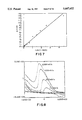
- FIG. 7 is a plot of peak current as determined from cyclic voltammograms vs. oxygen concentration in the range from 0.1% to 99% that may be used as a standard curve.
- FIG. 8 is a cyclic voltammogram of a sensor in air at different sweep rates from 100 to 2000 mV/s.
- FIG. 9 is a plot of peak current vs. the square root of potential sweep rate in mV/s (V 1/2 ).
- FIG. 10A is a cyclic voltammogram of a NO sensor in a gas mixture containing 1000 ppm NO.
- FIG. 10B is a cyclic voltammogram of a NO sensor in a gas mixture containing 800 ppm NO.
- FIG. 10C is a cyclic voltammogram of a NO sensor in a gas mixture containing 500 ppm NO.
- FIG. 10D is a cyclic voltammogram of a NO sensor in a gas mixture containing 330 ppm NO.
- FIG. 10E is a cyclic voltammogram of a NO sensor in a gas mixture containing 100 ppm NO.
- FIG. 11 is a plot of peak current vs. concentration of NO that may be used as a calibration curve.
- FIG. 12A is a cyclic voltammogram of a NO sensor gas mixture containing 500 ppm NO and 1.9%O 2 .
- FIG. 12B is a cyclic voltammogram of a NO sensor an a gas mixture containing 330 ppm NO and 1.3% 2 .
- FIG. 12C is a cyclic voltammogram of a NO sensor an a gas mixture containing 100 ppm NO and 1.8% 2 .
- FIG. 12D is a cyclic voltammogram of a NO sensor an a gas mixture containing 500 ppm NO and 1.0% 2 .
- FIG. 13A is a cyclic voltammogram of a NO sensor an a gas mixture of 970 ppm NO and 660 ppm O 2 .
- FIG. 13B is a cyclic voltammogram of a NO sensor an a gas mixture of 800 ppm NO and 4000 ppm O 2 .
- FIG. 13C is a cyclic voltammogram of a NO sensor gas mixture of 900 ppm NO and 2000 ppm O 2 .
- FIG. 13D is a cyclic voltammogram of a NO sensor gas mixture of 670 ppm NO and 6700 ppm O 2 .
- FIG. 14A is a cyclic voltammogram of a NO x sensor in an NO concentration of 1000 ppm and a sweep rate of 100 mV/s at 500° C.
- FIG. 14B is a cyclic voltammogram of a NO x sensor in an NO concentration of 1000 ppm and a sweep rate of 100 mV/s at 400° C.
- FIG. 14C is a cyclic voltammogram of a NO x sensor in an NO concentration of 1000 ppm and a sweep rate of 100 mV/s at 450° C.
- FIG. 14D is a cyclic voltammogram of a NO x sensor in an NO concentration of 1000 ppm and a sweep rate of 100 mV/s at 350° C.
- FIG. 15A is a cyclic voltammogram of a NO x sensor at 500 ppm NO with H 2 as an interfering species.
- FIG. 15B is a cyclic voltammogram of a NO x sensor at 500 ppm NO with 500 ppm CH 4 as an interfering species.
- FIG. 15C is a cyclic voltammogram of a NO x sensor at 500 ppm NO with 10%CO 2 as an interfering species.
- FIG. 15D is a cyclic voltammogram of a NO x sensor at 500 ppm NO with 500 ppm CO as an interfering species.
- FIG. 15E is a cyclic voltammogram of a NO x sensor at 500 ppm NO with 500 ppm H 2 as an interfering species.
- FIG. 15F is a cyclic voltammogram of a NO x sensor at 500 ppm NO with 500 ppm H 2 and 0.7% O 2 as interfering species.
- FIG. 16A is a cyclic voltammogram of a NO x sensor in 500 ppm NO with no H 2 O vapor.
- FIG. 16B is a cyclic voltammogram of a NO x sensor in 500 ppm NO with 25% H 2 O vapor.
- FIG. 16C is a cyclic voltammogram of a NO x sensor in 500 ppm NO with 3% H 2 O vapor.
- FIG. 16D is a cyclic voltammogram of a NO x sensor in 500 ppm NO with no H 2 O vapor, after the sensor had been tested in a moisture environment.
- FIG. 17A is a cyclic voltammogram of a NO x sensor at 100 ppm NO in a mixture of interfering species of CO 2 , CH 2 , O 2 , and H 2 O.
- FIG. 17B is a cyclic voltammogram of a NO x sensor at 330 ppm NO with the same mixture of interfering species as in FIG. 17A.
- FIG. 17C is a cyclic voltammogram of a NO x sensor at 200 ppm NO with the same mixture of interfering species as in FIG. 17A and FIG. 17B.
- FIG. 17D is a cyclic voltammogram of a NO x sensor at 500 ppm NO with the same mixture of interfering species as in FIGS. 17A-17C.
- FIG. 18A is a cyclic voltammogram of a NO x sensor in an environment of NO, CO 2 , CH 4 and H 2 O, with 0.2% O 2 .
- FIG. 18B is a cyclic voltammogram of the NO x sensor of FIG. 18A, with the same concentration of NO, CO 2 , CH 4 and H 2 O, with 2.1% O 2 .
- FIG. 18C is a cyclic voltammogram of the NO x sensor of FIGS. 18A and 18B, with the same concentration of NO, CO 2 , CH 4 and H 2 O, with 0.67% O 2 .
- FIG. 18D is a cyclic voltammogram of the NO x sensor of FIGS. 18A-18C, with the same concentration of NO, CO 2 , CH 4 and H 2 O, with 4.2% O 2 .
- FIG. 19A is a cyclic voltammogram of a NO x sensor at 1000 ppm NO after storage in ambient atmosphere for 3 months.
- FIG. 19B is a cyclic voltammogram of a NO x sensor at 800 ppm NO and 0.4% O 2 after storage in ambient atmosphere for 3 months.
- FIG. 19C is a cyclic voltammogram of a NO x sensor at 1000 ppm NO after storage in ambient atmosphere for 3 months.
- FIG. 19D is a cyclic voltammogram of a NO x sensor at 800 ppm NO and 0.4% O 2 after storage in ambient atmosphere for 3 months.
- a multi-functional sensor 110 for a natural gas combustion system includes an ion-conductive electrolyte membrane 112 constructed from ceramic solid oxide material.
- the particular composition of the electrolyte membrane may vary according to the requirements of particular applications, and specific materials will be discussed later with regard to specific embodiments.
- Electrolyte membrane 112 has a fast surface 114 proximal the exhaust stream from a natural gas combustion system, and an opposing second surface 116 isolated from the exhaust stream.
- a sensing electrode 120 adheres to at least a portion of fast surface 114 of the electrolyte membrane, and a counter-electrode 122 adheres to a portion of the second surface 116.
- the sensing electrode includes a porous layer of catalytic material (e.g.
- sensing and counter-electrodes 120 and 122 also may vary according to the requirements of particular applications, and will also be discussed later with regard to specific embodiments.
- a reference electrode 124 (made of e.g. platinum) may be adhered to the second surface 116 proximal the counter-electrode.
- Sensing electrode 120 may be covered by a porous diffusion barrier 126 which limits the amount of exhaust gas that may diffuse to the sensing electrode.
- the diffusion barrier is constructed from the same material as the electrolyte membrane to eliminate complications from thermal expansion mismatches and to avoid chemical interactions.
- the diffusion barrier may be constructed from alumina.
- an exhaust gas compartment 132 in fluid communication with the exhaust stream is disposed between diffusion barrier 126 and electrolyte membrane 112. Fluid access to the exhaust gas compartment may be had through diffusion aperture 128.
- the exhaust gas compartment allows exhaust gases entering through diffusion aperture 128 to diffuse out and contact a larger area of the sensing electrode 120.
- Exhaust gas compartment 132 is sealed around its edges to the diffusion barrier 126 and the electrolyte membrane 112 by glass seals 136 at the ends of ceramic spacers 138.
- the atmosphere inside the exhaust gas compartment is limited to exhaust gases that diffuse in through the diffusion aperture.
- Sensing electrode 120, counter-electrode 122, and reference electrode 124 are electrically connected via electrical connection means 140 enabling a voltage potential indicated by reference letter V to be applied between the sensing electrode and the reference electrode. If no reference electrode is present, this potential is applied between the sensing and counter electrodes.
- the electrical connection means also enables an electrical current indicated by reference letter i to flow between the sensing electrode and the counter-electrode.
- electrical connections are silver wire of 0.25 mm (0.01") in diameter, connected to the electrodes with a small amount of silver paste. The resulting connections may be fired at 500° C. for 30 minutes to set-up the silver paste, and bond the electrical connections to the electrodes.
- the senor 110 is mounted in the wall 144 of the exhaust pipe from a natural gas combustion system. Exhaust gases from the exhaust stream are in fluid communication with the diffusion barrier 126, and thus free to diffuse through diffusion aperture 128 to sensing electrode 120, while both counter-electrode 122 and reference electrode 124 are isolated from the exhaust stream in a separate air atmosphere. Such a configuration is optional though, and the counter and reference electrodes may also be in fluid communication with the exhaust stream.
- Each sensing electrode may be constructed from a material having a high selectivity for a specific component in the exhaust gas stream.
- High selectivity to a chemical species results from specific adsorption of the chemical species at a catalyst.
- the catalysts used for NO x sensors strongly adsorb NO x at the electrode surface, whereas other gas components in the mixture are physically inaccessible to the electrode. In this manner, sensors highly selective to, e.g. NO x , CO, unburned hydrocarbons, and other combustion products can be constructed.
- exhaust gases from the combustion system diffuse through diffusion aperture 128 into the exhaust gas compartment 132 where they contact the sensing electrode 120.
- a negative voltage potential is applied to sensing electrode 120 with respect to reference electrode 124 which is exposed to air.
- a positive voltage potential is applied to sensing electrode 120 with respect to reference electrode 124 which is exposed to a hydrogen-containing atmosphere.
- the counter-electrode 122 in both cases may be exposed to air.
- sensing electrode 120 the cathode
- the oxide is reduced, and the oxygen ions move through ion-conductive electrolyte membrane 112 to counter-electrode 122 (the anode) where they are oxidized to oxygen molecules in the air environment.
- sensing electrode 120 the anode
- the species is oxidized, and the protons move through the electrolyte membrane to counter-electrode 122 (the cathode) where they are reduced to hydrogen molecules.
- Electrons involved in the redox reactions move from anode to cathode through electrical connection means 140 enabling measurement of an electrical current, the magnitude of which is proportional to concentration of the chemical species involved in the redox reaction.
- sensor response is dependent upon the exhaust stream's flow pattern.
- the flow pattern can be regulated, however, by the configuration of diffusion barrier 126 and the pore size of diffusion aperture 128.
- the gas mixture near the surface of sensing electrode 120 will be barely convective.
- sensor response will show standard steady-state voltammetric waves with current peaks at discrete characteristic potentials associated with certain chemical species.
- the fluxes are additive and the i-E or i-t curves for the mixture are the sum of the individual i-E curves of each species as illustrated in FIG. 4.
- the peak currents for the subsequent species must be corrected using the decaying current of the previous wave as the baseline. Accordingly, a given chemical species can be distinguished by the characteristic potentials (E p ) at which current reaches a maximum while the species' concentration can be estimated from the peak current (I p ).
- each component gas can be detected independently and distinguished by the potential at which the limiting current occurs as illustrated in FIG. 5.
- the concentration of each gas component can be estimated from the limiting current associated with the gas. Again, the limiting current for the subsequent process has to be corrected by subtracting the limiting current of the previous process.
- each electrode has high selectivity for a specific gas component in the exhaust stream. Due to the fact that electrode kinetics can significantly shift the potential from the thermodynamic value at which redox reactions occur, this potential shift can be tailored by means of electrocatalysis to detect each gas component in the exhaust stream selectively.
- the high selectivity to a chemical species stems from the specific adsorption of the species at the catalyst. The sensor response is thus directly related to the surface coverage, while the gas concentration is obtainable from a suitable adsorption isotherm such as the Langmuir isotherm.
- composition of both ion-conductive electrolyte and electrode materials may be varied according to the requirements of particular applications.
- any suitable oxygen anion conductors can be used for oxygen containing gases
- any suitable proton conductors can be used as electrolyte for hydrogen-containing gases.
- zirconia-based ceramics such as tape-cast yttrium-strontium-zirconium (YSZ) with a thickness less than 0.2 mm
- thoria-based ceramics are suitable electrolyte materials for voltammetric sensors for oxygen containing gases.
- Electrode materials suitable for oxygen-containing gases include noble metals (Pt, Ag, Au, etc.), perovskites (LSM, LSCo, and modified LSM and LSCo, etc.), and other mixed oxides and transition metal sulfides and of mixture of them.
- Electrode materials suitable for reduction of NO x , SO x , CO 2 , H 2 O, as well as for oxidation of H 2 , CH 4 and other unburned hydrocarbons include alumina-iron based catalysts, vanadia based catalysts (V 2 O 5 /TiO 2 , V 2 O 5 /Al 2 O 3 , V 2 O 5 /SiO 2 , etc.), nickel-based catalysts, and rare earth metals or other metal oxide based catalysts and the mixture of them.
- V 2 O 5 based catalysts containing 50% of solid, which consists of 10 mol % of V 2 O 5 and 90 mol % TiO 2 is a suitable catalyst for sensors detecting NO x and O 2 .
- the sensor can be operated in an amperometric mode whereby a steady electrical potential is applied to the sensor and the current response carries information about the chemical species undergoing reduction or oxidation.
- Amperometric sensors based on bismuth oxide-based ionic conductors have the attractive features of fast response (less than 30 seconds) and high sensitivity to oxygen, particularly in low concentrations.
- FIG. 6 Several batches of voltammetric sensors were fabricated, arranged as per FIG. 1, having diffusion barriers made in different ways (laser-drilled and fiber-introduced holes) and having varying pore sizes (e.g. from 10 to 200 ⁇ m). Several typical voltammograms from these sensors are illustrated in FIG. 6 (O 2 --N 2 mixture at 450° C. with a sweep rate of 100 mV/s).
- Fabricated sensors were positioned in a quartz tube which was placed in a tubular furnace controlled at a constant temperature. Pre-mixed sample gases were flowed through the quartz tube at a controlled flow rate, typically from 60 to 150 cc/min. Each and every gaseous component in the mixture is adjustable individually.
- a potentiostat/galvanostat (EG&G PAR 273) interfaced with a computer (IBM 286) was used to sweep the potential and to collect the current response of sensors under testing.
- the voltammograms were displayed on the computer screen after each potential sweep, and were recorded by a printer (FIG. 6).
- FIG. 7 A typical plot of peak current, as determined from cyclic voltammograms, versus oxygen concentration in the range from 0.1% to 99% is depicted in FIG. 7.
- the peak currents, i p depend linearly on -1 n(1-X O2 ) over a wide concentration range, where X O2 is the molar fraction of oxygen in the gas mixtures. This also indicates that the oxygen transports through the diffusion aperture by normal diffusion.
- FIG. 8 contains some cyclic voltammograms of a sensor according to the invention in air at different sweep rates, from 100 to 2000 mV/s.
- the sharp current peaks for oxygen reduction at potential sweep rate of 2000 mV/s indicate that, in principle, this sensor is capable of generating a sensing signal in less that one second.
- the peak current (mA) versus V 1/2 (square root of potential sweep rate in mV/s) of a voltammetric sensor according to the invention in air at 500° C. has a linear relationship, indicating that the reduction waves are in good shape.
- FIGS. 10A-10E are typical voltammograms of a V 2 O 5 coated NO sensor in gas mixtures containing different concentrations of NO at 500° C. and 100 mV/s. Clearly, the sensor responded to NO very well at about -0.8 V and peak current changed according to the concentration of NO. The linear relationship between peak current and concentration NO shown in FIG. 11 can be used as a calibration curve.
- FIGS. 12A-12D and 13A-13D are voltammograms of a NO sensor in gas mixtures containing various concentrations of oxygen and NO.
- the sensor's selectivity to NO in a gas containing both NO and O 2 is about 10 times better than the selectivity to O 2 .
- the response of the sensor to oxygen concentrations less than 2000 ppm is barely observable.
- the concentration of O 2 is less than 2000 ppm
- oxygen has no effect on detection of NO.
- the reduction potential for oxygen is well separated from the reduction potential for NO so that NO can be detected in the presence of oxygen.
- FIG. 6 shows that CO, CO 2 , and hydrocarbons have no interference to the measurement of O 2 and NO.
- FIGS. 14A-14D Temperature dependence of peak current over the temperature range from 350° to 500° C. is shown in FIGS. 14A-14D. Clearly, as the operating temperature increases, the signal to noise ratio also increases.
- the oxygen signal can be easily determined when its concentration was higher than 0.2%.
- the current peak for NO x was still obvious even with the existence of 4.2% oxygen.
- the position of the NO x current peak also did not move when the oxygen concentration was changed from 0.2% to 4.2% in the gas mixtures. In both cases, no other peaks appeared in the voltage range studied other than the peaks due to the reduction of NO x and O 2 , indicating that the sensor was inert to the other gases such as CO 2 and CH 4 .
Landscapes
- Chemical & Material Sciences (AREA)
- Life Sciences & Earth Sciences (AREA)
- Health & Medical Sciences (AREA)
- Pathology (AREA)
- General Physics & Mathematics (AREA)
- Immunology (AREA)
- Physics & Mathematics (AREA)
- Analytical Chemistry (AREA)
- Biochemistry (AREA)
- General Health & Medical Sciences (AREA)
- Chemical Kinetics & Catalysis (AREA)
- Electrochemistry (AREA)
- Molecular Biology (AREA)
- Engineering & Computer Science (AREA)
- Combustion & Propulsion (AREA)
- Food Science & Technology (AREA)
- Medicinal Chemistry (AREA)
- Measuring Oxygen Concentration In Cells (AREA)
Priority Applications (2)
| Application Number | Priority Date | Filing Date | Title |
|---|---|---|---|
| US08/482,958 US5667652A (en) | 1993-11-19 | 1995-06-15 | Multi-functional sensor for combustion systems |
| US08/808,240 US6051123A (en) | 1995-06-15 | 1997-02-28 | Multi-functional and NOx sensor for combustion systems |
Applications Claiming Priority (4)
| Application Number | Priority Date | Filing Date | Title |
|---|---|---|---|
| WOPCT/US93/11274 | 1993-11-19 | ||
| PCT/US1993/011274 WO1995014226A1 (fr) | 1993-11-19 | 1993-11-19 | Detecteur multifonctions pour systemes de combustion |
| US16414393A | 1993-12-09 | 1993-12-09 | |
| US08/482,958 US5667652A (en) | 1993-11-19 | 1995-06-15 | Multi-functional sensor for combustion systems |
Related Parent Applications (1)
| Application Number | Title | Priority Date | Filing Date |
|---|---|---|---|
| US16414393A Continuation | 1993-11-19 | 1993-12-09 |
Related Child Applications (1)
| Application Number | Title | Priority Date | Filing Date |
|---|---|---|---|
| US08/808,240 Continuation-In-Part US6051123A (en) | 1995-06-15 | 1997-02-28 | Multi-functional and NOx sensor for combustion systems |
Publications (1)
| Publication Number | Publication Date |
|---|---|
| US5667652A true US5667652A (en) | 1997-09-16 |
Family
ID=22237202
Family Applications (1)
| Application Number | Title | Priority Date | Filing Date |
|---|---|---|---|
| US08/482,958 Expired - Lifetime US5667652A (en) | 1993-11-19 | 1995-06-15 | Multi-functional sensor for combustion systems |
Country Status (2)
| Country | Link |
|---|---|
| US (1) | US5667652A (fr) |
| WO (1) | WO1995014226A1 (fr) |
Cited By (23)
| Publication number | Priority date | Publication date | Assignee | Title |
|---|---|---|---|---|
| US5996337A (en) * | 1998-02-06 | 1999-12-07 | Engelhard Corporation | Dynamic calorimetric sensor system |
| US6071476A (en) * | 1997-11-14 | 2000-06-06 | Motorola, Inc. | Exhaust gas sensor |
| US6293093B1 (en) * | 2000-08-02 | 2001-09-25 | Ford Global Technologies, Inc | Method and system for directly monitoring the efficiency of a conditioning catalyst having negligible oxygen storage capacity |
| EP0982586A3 (fr) * | 1998-08-25 | 2001-10-24 | Ngk Insulators, Ltd. | Détecteur de monoxyde de carbone, méthode de fabrication et méthode d'utilisation de celui-ci |
| US6378295B1 (en) * | 1998-04-29 | 2002-04-30 | Siemens Aktiengesellschaft | Method for cleaning exhaust gas with trimming control |
| US6385966B2 (en) * | 1998-07-09 | 2002-05-14 | Siemens Aktiengesellschaft | Method for regenerating an NOx storage catalyst |
| US20030136674A1 (en) * | 1998-07-08 | 2003-07-24 | Ngk Insulators, Ltd. | Gas sensor and nitrogen oxide sensor |
| US6716327B1 (en) * | 1996-09-02 | 2004-04-06 | Robert Bosch Gmbh | Measuring arrangement for the determination of gas components in a gas mixtures |
| US20060120920A1 (en) * | 2004-12-06 | 2006-06-08 | Gas Technology Institute | Hydrogen or helium sensor |
| US20070029210A1 (en) * | 2005-08-02 | 2007-02-08 | The Ohio State University | High temperature total NOx sensor |
| WO2007149471A3 (fr) * | 2006-06-20 | 2008-11-20 | Fluid Analytics Inc | Capteur chimique électrocatalytique et procédé destiné à retirer des produits chimiques cibles d'un flux de gaz |
| US7611612B2 (en) | 2005-07-14 | 2009-11-03 | Ceramatec, Inc. | Multilayer ceramic NOx gas sensor device |
| US20140212979A1 (en) * | 2013-01-31 | 2014-07-31 | Sensirion Ag | Diffusion based metal oxide gas sensor |
| WO2015004846A1 (fr) * | 2013-07-12 | 2015-01-15 | Toyota Jidosha Kabushiki Kaisha | Dispositif de détection de la concentration en sox d'un moteur à combustion interne |
| JP2015017932A (ja) * | 2013-07-12 | 2015-01-29 | 株式会社日本自動車部品総合研究所 | 内燃機関のSOx濃度検出装置 |
| JP2015017931A (ja) * | 2013-07-12 | 2015-01-29 | トヨタ自動車株式会社 | 内燃機関のSOx濃度検出装置 |
| US20160349206A1 (en) * | 2014-02-20 | 2016-12-01 | Toyota Jidosha Kabushiki Kaisha | Control system and control method for internal combustion engine |
| DE102015008638A1 (de) | 2015-07-03 | 2017-01-05 | Kurt-Schwabe-Institut für Mess- und Sensortechnik e.V. Meinsberg | Verfahren zur selektiven Bestimmung redoxaktiver Gase in Gasgemischen mit einem Festelektrolytsensor |
| DE102016212948A1 (de) * | 2016-07-15 | 2017-08-24 | Continental Automotive Gmbh | Wasserstoffsensor zur Ermittlung eines Wasserstoffgehalts eines Gases |
| JP2018091662A (ja) * | 2016-11-30 | 2018-06-14 | トヨタ自動車株式会社 | ガス検出装置 |
| JP2018132317A (ja) * | 2017-02-13 | 2018-08-23 | トヨタ自動車株式会社 | ガス検出装置 |
| CN105393115B (zh) * | 2013-07-12 | 2018-08-31 | 丰田自动车株式会社 | 内燃发动机的SOx浓度检测设备 |
| US10667732B2 (en) * | 2017-05-12 | 2020-06-02 | The Florida International University Board Of Trustees | Method for transdermal measurement of volatile anesthetics |
Families Citing this family (13)
| Publication number | Priority date | Publication date | Assignee | Title |
|---|---|---|---|---|
| JP3311218B2 (ja) * | 1995-11-02 | 2002-08-05 | 松下電器産業株式会社 | 炭化水素センサ |
| WO1997042495A1 (fr) * | 1996-05-07 | 1997-11-13 | Sri International | Pile electrochimique solide permettant de mesurer les composants d'un melange de gaz et methode de mesure correspondante |
| DE69735302T8 (de) * | 1996-09-17 | 2007-03-01 | Kabushiki Kaisha Riken | Gas sensor |
| DE69739309D1 (de) * | 1996-12-29 | 2009-04-30 | Ngk Spark Plug Co | Abgassensorsystem |
| JP3534612B2 (ja) | 1998-05-18 | 2004-06-07 | 日本特殊陶業株式会社 | 平面型限界電流式センサ |
| US7404882B2 (en) | 1999-11-19 | 2008-07-29 | Perkinelmer Las, Inc. | Film-type solid polymer ionomer sensor and sensor cell |
| US6682638B1 (en) * | 1999-11-19 | 2004-01-27 | Perkin Elmer Llc | Film type solid polymer ionomer sensor and sensor cell |
| JP2001215214A (ja) | 1999-11-24 | 2001-08-10 | Ngk Spark Plug Co Ltd | 水素ガスセンサ |
| CA2400882A1 (fr) * | 2001-09-03 | 2003-03-03 | Tomonori Kondo | Detecteur de gaz |
| DE102005049775A1 (de) * | 2005-10-18 | 2007-04-19 | Robert Bosch Gmbh | Sensor zur Messung der Konzentration einer Gaskomponente in einem Gasgemisch und Verfahren zur Herstellung einer Elektrode eines solchen Sensors |
| US9494493B2 (en) | 2013-04-12 | 2016-11-15 | Siemens Energy, Inc. | Single dynamic pressure sensor based flame monitoring of a gas turbine combustor |
| EP2789914A1 (fr) | 2013-04-12 | 2014-10-15 | Siemens Aktiengesellschaft | Procédé destiné à la surveillance d'un état de flamme |
| US9599527B2 (en) | 2015-04-21 | 2017-03-21 | Siemens Energy, Inc. | Dynamic pressure method of detecting flame on/off in gas turbine combustion cans for engine protection |
Citations (37)
| Publication number | Priority date | Publication date | Assignee | Title |
|---|---|---|---|---|
| US3989614A (en) * | 1975-01-08 | 1976-11-02 | Tseng Ying Tien | Gas sensor |
| US4044601A (en) * | 1974-07-29 | 1977-08-30 | Hitachi, Ltd. | Smoke and gas sensor element |
| US4135381A (en) * | 1977-07-11 | 1979-01-23 | General Motors Corporation | Oxygen sensor temperature monitor for an engine exhaust monitoring system |
| US4151503A (en) * | 1977-10-05 | 1979-04-24 | Ford Motor Company | Temperature compensated resistive exhaust gas sensor construction |
| US4190499A (en) * | 1973-03-27 | 1980-02-26 | Westinghouse Electric Corp. | Combustibles sensor |
| JPS5599063A (en) * | 1979-01-24 | 1980-07-28 | Hitachi Ltd | Measuring apparatus for oxygen concentration |
| US4227974A (en) * | 1976-06-18 | 1980-10-14 | Bayer Aktiengesellschaft | Electrochemical cell having a polarographic device with ion selective electrode as working electrode and method of use |
| EP0025625A1 (fr) * | 1979-09-13 | 1981-03-25 | Koninklijke Philips Electronics N.V. | Dispositif d'analyse de gaz |
| US4272331A (en) * | 1980-03-03 | 1981-06-09 | Ford Motor Company | Oscillatory mode oxygen sensor and method |
| US4292158A (en) * | 1979-06-09 | 1981-09-29 | Robert Bosch Gmbh | Oxygen sensor of the polarographic type, particularly for use with internal combustion engines |
| US4298573A (en) * | 1979-05-19 | 1981-11-03 | Nissan Motor Company, Limited | Device for detection of oxygen concentration in combustion gas |
| US4300991A (en) * | 1979-06-13 | 1981-11-17 | Nissan Motor Company, Limited | Air-fuel ratio detecting apparatus |
| US4305724A (en) * | 1980-08-04 | 1981-12-15 | Delphian Partners | Combustible gas detection system |
| US4306957A (en) * | 1979-07-28 | 1981-12-22 | Nissan Motor Co., Ltd. | Device for producing control signal for feedback control of air/fuel ratio |
| US4314996A (en) * | 1979-04-04 | 1982-02-09 | Matsushita Electric Industrial Company, Limited | Oxygen sensor |
| US4345985A (en) * | 1979-12-26 | 1982-08-24 | Nissan Motor Company, Limited | Method of producing solid electrolyte oxygen-sensing element of laminated structure |
| US4356065A (en) * | 1977-03-18 | 1982-10-26 | Robert Bosch Gmbh | Polarographic oxygen concentration sensor and method of determining oxygen content in the exhaust gases of an internal combustion engine |
| US4487680A (en) * | 1983-04-18 | 1984-12-11 | Ford Motor Company | Planar ZrO2 oxygen pumping sensor |
| US4502939A (en) * | 1980-05-10 | 1985-03-05 | Robert Bosch Gmbh | Electrochemical oxygen sensor, particularly for analysis of combustion cases from internal combustion engines |
| US4522690A (en) * | 1983-12-01 | 1985-06-11 | Honeywell Inc. | Electrochemical sensing of carbon monoxide |
| US4570479A (en) * | 1983-07-25 | 1986-02-18 | Toyota Jidosha Kabushiki Kaisha | Air-fuel ratio detector and method of measuring air-fuel ratio |
| US4572900A (en) * | 1984-04-25 | 1986-02-25 | The United States Of America As Represented By The Secretary Of The Navy | Organic semiconductor vapor sensing method |
| JPS6184552A (ja) * | 1984-10-02 | 1986-04-30 | Fuji Electric Co Ltd | ガス分析機器 |
| DE3525774A1 (de) * | 1985-07-19 | 1987-01-29 | Hoelter Heinz | Verfahren zur stabilisierung von halbleitergassensoren durch erhoehung der schadstoffkonzentrationen, vorzugsweise fuer kraftfahrzeuge |
| US4792433A (en) * | 1982-08-27 | 1988-12-20 | Tokyo Shibaura Denki Kabushiki Kaisha | CO gas detecting device and circuit for driving the same |
| JPS6476948A (en) * | 1987-09-17 | 1989-03-23 | Mitsubishi Cable Ind Ltd | Production of superconducting material |
| US4832818A (en) * | 1986-12-19 | 1989-05-23 | Matsushita Electric Industrial Co., Ltd. | Air/fuel ratio sensor |
| JPH0225741A (ja) * | 1988-07-14 | 1990-01-29 | Mazda Motor Corp | 排ガスセンサ |
| US4990235A (en) * | 1989-02-23 | 1991-02-05 | Toyota Jidosha Kabushiki | Oxygen sensor |
| US5012671A (en) * | 1988-11-15 | 1991-05-07 | Ricoh Company, Ltd. | Gas detecting device |
| US5120422A (en) * | 1991-03-01 | 1992-06-09 | Ceramatec, Inc. | Sodium ion sensor |
| US5173166A (en) * | 1990-04-16 | 1992-12-22 | Minitech Co. | Electrochemical gas sensor cells |
| US5178744A (en) * | 1988-10-31 | 1993-01-12 | Fujikura Ltd. | Oxygen sensor device |
| US5226309A (en) * | 1992-06-18 | 1993-07-13 | Illinois Institute Of Technology | Halogenated compounds sensor |
| US5273628A (en) * | 1992-05-11 | 1993-12-28 | Gas Research Institute | Mixed ionic-electronic conductors for oxygen separation and electrocatalysis |
| US5279145A (en) * | 1990-10-22 | 1994-01-18 | Mitsubishi Denki K.K. | Heater control device for an air-fuel ratio sensor |
| US5397442A (en) * | 1994-03-09 | 1995-03-14 | Gas Research Institute | Sensor and method for accurately measuring concentrations of oxide compounds in gas mixtures |
-
1993
- 1993-11-19 WO PCT/US1993/011274 patent/WO1995014226A1/fr not_active Ceased
-
1995
- 1995-06-15 US US08/482,958 patent/US5667652A/en not_active Expired - Lifetime
Patent Citations (37)
| Publication number | Priority date | Publication date | Assignee | Title |
|---|---|---|---|---|
| US4190499A (en) * | 1973-03-27 | 1980-02-26 | Westinghouse Electric Corp. | Combustibles sensor |
| US4044601A (en) * | 1974-07-29 | 1977-08-30 | Hitachi, Ltd. | Smoke and gas sensor element |
| US3989614A (en) * | 1975-01-08 | 1976-11-02 | Tseng Ying Tien | Gas sensor |
| US4227974A (en) * | 1976-06-18 | 1980-10-14 | Bayer Aktiengesellschaft | Electrochemical cell having a polarographic device with ion selective electrode as working electrode and method of use |
| US4356065A (en) * | 1977-03-18 | 1982-10-26 | Robert Bosch Gmbh | Polarographic oxygen concentration sensor and method of determining oxygen content in the exhaust gases of an internal combustion engine |
| US4135381A (en) * | 1977-07-11 | 1979-01-23 | General Motors Corporation | Oxygen sensor temperature monitor for an engine exhaust monitoring system |
| US4151503A (en) * | 1977-10-05 | 1979-04-24 | Ford Motor Company | Temperature compensated resistive exhaust gas sensor construction |
| JPS5599063A (en) * | 1979-01-24 | 1980-07-28 | Hitachi Ltd | Measuring apparatus for oxygen concentration |
| US4314996A (en) * | 1979-04-04 | 1982-02-09 | Matsushita Electric Industrial Company, Limited | Oxygen sensor |
| US4298573A (en) * | 1979-05-19 | 1981-11-03 | Nissan Motor Company, Limited | Device for detection of oxygen concentration in combustion gas |
| US4292158A (en) * | 1979-06-09 | 1981-09-29 | Robert Bosch Gmbh | Oxygen sensor of the polarographic type, particularly for use with internal combustion engines |
| US4300991A (en) * | 1979-06-13 | 1981-11-17 | Nissan Motor Company, Limited | Air-fuel ratio detecting apparatus |
| US4306957A (en) * | 1979-07-28 | 1981-12-22 | Nissan Motor Co., Ltd. | Device for producing control signal for feedback control of air/fuel ratio |
| EP0025625A1 (fr) * | 1979-09-13 | 1981-03-25 | Koninklijke Philips Electronics N.V. | Dispositif d'analyse de gaz |
| US4345985A (en) * | 1979-12-26 | 1982-08-24 | Nissan Motor Company, Limited | Method of producing solid electrolyte oxygen-sensing element of laminated structure |
| US4272331A (en) * | 1980-03-03 | 1981-06-09 | Ford Motor Company | Oscillatory mode oxygen sensor and method |
| US4502939A (en) * | 1980-05-10 | 1985-03-05 | Robert Bosch Gmbh | Electrochemical oxygen sensor, particularly for analysis of combustion cases from internal combustion engines |
| US4305724A (en) * | 1980-08-04 | 1981-12-15 | Delphian Partners | Combustible gas detection system |
| US4792433A (en) * | 1982-08-27 | 1988-12-20 | Tokyo Shibaura Denki Kabushiki Kaisha | CO gas detecting device and circuit for driving the same |
| US4487680A (en) * | 1983-04-18 | 1984-12-11 | Ford Motor Company | Planar ZrO2 oxygen pumping sensor |
| US4570479A (en) * | 1983-07-25 | 1986-02-18 | Toyota Jidosha Kabushiki Kaisha | Air-fuel ratio detector and method of measuring air-fuel ratio |
| US4522690A (en) * | 1983-12-01 | 1985-06-11 | Honeywell Inc. | Electrochemical sensing of carbon monoxide |
| US4572900A (en) * | 1984-04-25 | 1986-02-25 | The United States Of America As Represented By The Secretary Of The Navy | Organic semiconductor vapor sensing method |
| JPS6184552A (ja) * | 1984-10-02 | 1986-04-30 | Fuji Electric Co Ltd | ガス分析機器 |
| DE3525774A1 (de) * | 1985-07-19 | 1987-01-29 | Hoelter Heinz | Verfahren zur stabilisierung von halbleitergassensoren durch erhoehung der schadstoffkonzentrationen, vorzugsweise fuer kraftfahrzeuge |
| US4832818A (en) * | 1986-12-19 | 1989-05-23 | Matsushita Electric Industrial Co., Ltd. | Air/fuel ratio sensor |
| JPS6476948A (en) * | 1987-09-17 | 1989-03-23 | Mitsubishi Cable Ind Ltd | Production of superconducting material |
| JPH0225741A (ja) * | 1988-07-14 | 1990-01-29 | Mazda Motor Corp | 排ガスセンサ |
| US5178744A (en) * | 1988-10-31 | 1993-01-12 | Fujikura Ltd. | Oxygen sensor device |
| US5012671A (en) * | 1988-11-15 | 1991-05-07 | Ricoh Company, Ltd. | Gas detecting device |
| US4990235A (en) * | 1989-02-23 | 1991-02-05 | Toyota Jidosha Kabushiki | Oxygen sensor |
| US5173166A (en) * | 1990-04-16 | 1992-12-22 | Minitech Co. | Electrochemical gas sensor cells |
| US5279145A (en) * | 1990-10-22 | 1994-01-18 | Mitsubishi Denki K.K. | Heater control device for an air-fuel ratio sensor |
| US5120422A (en) * | 1991-03-01 | 1992-06-09 | Ceramatec, Inc. | Sodium ion sensor |
| US5273628A (en) * | 1992-05-11 | 1993-12-28 | Gas Research Institute | Mixed ionic-electronic conductors for oxygen separation and electrocatalysis |
| US5226309A (en) * | 1992-06-18 | 1993-07-13 | Illinois Institute Of Technology | Halogenated compounds sensor |
| US5397442A (en) * | 1994-03-09 | 1995-03-14 | Gas Research Institute | Sensor and method for accurately measuring concentrations of oxide compounds in gas mixtures |
Non-Patent Citations (35)
| Title |
|---|
| Fukui et al., "CO Detection by BaO and Y2 O3 Dispersed SnO2 Ceramics", Symp. Proc. on Chemical Sensors, Electrochem. Soc., ed. D.R. Turner, pp. 187-195, 1987 month unavailable. |
| Fukui et al., CO Detection by BaO and Y 2 O 3 Dispersed SnO 2 Ceramics , Symp. Proc. on Chemical Sensors, Electrochem. Soc., ed. D.R. Turner, pp. 187 195, 1987 month unavailable. * |
| Heyne et al., "The Speed of Response of Solid Electrolyte Galvanic Cells for Gas Sensing", Journal of the Electrochemical Society, vol. 124, pp. 727-735, May, 1977. |
| Heyne et al., The Speed of Response of Solid Electrolyte Galvanic Cells for Gas Sensing , Journal of the Electrochemical Society, vol. 124, pp. 727 735, May, 1977. * |
| Heyne, L., Some Properties and Applications of Zirconia Based Solid Electrolyte Cells, Eindhoven, pp. 65 88, Sep. 1974. * |
| Heyne, L., Some Properties and Applications of Zirconia-Based Solid-Electrolyte Cells, Eindhoven, pp. 65-88, Sep. 1974. |
| Liaw et al, "Low Temperature Limiting-Current Oxygen Sensors Based on Tetragonal Zirconia Polycrystals", J. Electrochem. Soc. vol. 138, No. 8, Aug. 1991, pp. 2478-2483. |
| Liaw et al, Low Temperature Limiting Current Oxygen Sensors Based on Tetragonal Zirconia Polycrystals , J. Electrochem. Soc. vol. 138, No. 8, Aug. 1991, pp. 2478 2483. * |
| Liaw et al., "Novel Hydrogen Sensors For Use At Elevated Temperatures", Symp. Proc. on Chemical Sensors, Electrochem. Soc., ed. D.R. Turner, pp. 91-98, 1987 month unavailable. |
| Liaw et al., Novel Hydrogen Sensors For Use At Elevated Temperatures , Symp. Proc. on Chemical Sensors, Electrochem. Soc., ed. D.R. Turner, pp. 91 98, 1987 month unavailable. * |
| Liu et al., "Multifunctional Sensors Based on Ceramic Electrolytes", May 19, 1993. |
| Liu et al., Characterization of Mixed Ionic Electronic Conductors, published before Apr. 6, 1994. * |
| Liu et al., Characterization of Mixed Ionic-Electronic Conductors, published before Apr. 6, 1994. |
| Liu et al., Multifunctional Sensors Based on Ceramic Electrolytes , May 19, 1993. * |
| Liu, M., Electrode Kinetics and Transport Properties of Mixed Ionic Electronic Conductors, Ionic and Mixed Conducting Ceramics, PV 91 12, pp. 191 215, 1991; month unavailable. * |
| Liu, M., Electrode Kinetics and Transport Properties of Mixed Ionic-Electronic Conductors, Ionic and Mixed Conducting Ceramics, PV-91-12, pp. 191-215, 1991; month unavailable. |
| Liu, M., et al., Amperometric Sensors Based on Ceramic Membranes, 19 May, 1993. * |
| Liu, M., Oxygen Sensors, ASM Engineered materials Handbook, vol. 4, Ceramics and Glasses, pp. 363 372, 1986; month unavailable. * |
| Liu, M., Oxygen Sensors, ASM Engineered materials Handbook, vol. 4, Ceramics and Glasses, pp. 363-372, 1986; month unavailable. |
| Liu, M., Theoretical Assessment of Oxygen Separation Rates of Mixed Conductors, Ionic and Mixed Conducting Ceramics, PV 91 12, pp. 95 109, 1991; month unavailable. * |
| Liu, M., Theoretical Assessment of Oxygen Separation Rates of Mixed Conductors, Ionic and Mixed Conducting Ceramics, PV-91-12, pp. 95-109, 1991; month unavailable. |
| Logothetis, E.M., et al., A High Sensitivity Sensor for the Measurement of Combustible Gas Mixtures, Sensors and Conductors, 9, pp. 363 372, 1986; month unavailable. * |
| Logothetis, E.M., et al., A High-Sensitivity Sensor for the Measurement of Combustible Gas Mixtures, Sensors and Conductors, 9, pp. 363-372, 1986; month unavailable. |
| Logothetis, E.M., ZrO z Oxygen Sensors in Automotive Applications, Advances in Ceramics, vol. 3, Science and Technology of Zirconia (The American Ceramic Society 1981); month unavailable. * |
| Logothetis, E.M., ZrOz Oxygen Sensors in Automotive Applications, Advances in Ceramics, vol. 3, Science and Technology of Zirconia (The American Ceramic Society 1981); month unavailable. |
| Ogata et al., "CO2 gas sensor using β-Al2 O3 and metal carbonate", Journal of Materials Science Letters, 5, pp. 285-286, 1986 month unavailable. |
| Ogata et al., CO 2 gas sensor using Al 2 O 3 and metal carbonate , Journal of Materials Science Letters, 5, pp. 285 286, 1986 month unavailable. * |
| Sandler, Y.L., "The Response of the Stabilized Zirconia Galvanic Cell to Methane-Oxygen Mixtures", Journal of the Electrochemical Society, vol. 118, No. 8, pp. 1378-1381, Aug., 1971. |
| Sandler, Y.L., The Response of the Stabilized Zirconia Galvanic Cell to Methane Oxygen Mixtures , Journal of the Electrochemical Society, vol. 118, No. 8, pp. 1378 1381, Aug., 1971. * |
| Uchida et al., "High Temperature Hydrogen Sensor And Steam Sensor Using BaCeO3 -Based Proton Conducting Ceramics", Symp. Proc. on Chemical Sensors, Electrochem. Soc., ed. D.R. Turner, pp. 172-179, 1987 month unavailable. |
| Uchida et al., High Temperature Hydrogen Sensor And Steam Sensor Using BaCeO 3 Based Proton Conducting Ceramics , Symp. Proc. on Chemical Sensors, Electrochem. Soc., ed. D.R. Turner, pp. 172 179, 1987 month unavailable. * |
| Usiu, T. et al., Gas Polarographic Oxygen Sensor Using an Oxygen/Zirconia Electrolyte, J. Electrochem., Soc., vol. 135, No. 2, pp. 534 542, Feb., 1989. * |
| Usiu, T. et al., Gas Polarographic Oxygen Sensor Using an Oxygen/Zirconia Electrolyte, J. Electrochem., Soc., vol. 135, No. 2, pp. 534-542, Feb., 1989. |
| Usui et al., "Solid State Humidity Sensor Usable At High Temperatures", Symp. Proc. on Chemical Sensors, Electrochem. Soc., ed. D.R. Turner, pp. 202-211, 1987 month unavailable. |
| Usui et al., Solid State Humidity Sensor Usable At High Temperatures , Symp. Proc. on Chemical Sensors, Electrochem. Soc., ed. D.R. Turner, pp. 202 211, 1987 month unavailable. * |
Cited By (33)
| Publication number | Priority date | Publication date | Assignee | Title |
|---|---|---|---|---|
| US6716327B1 (en) * | 1996-09-02 | 2004-04-06 | Robert Bosch Gmbh | Measuring arrangement for the determination of gas components in a gas mixtures |
| US6071476A (en) * | 1997-11-14 | 2000-06-06 | Motorola, Inc. | Exhaust gas sensor |
| US5996337A (en) * | 1998-02-06 | 1999-12-07 | Engelhard Corporation | Dynamic calorimetric sensor system |
| US6378295B1 (en) * | 1998-04-29 | 2002-04-30 | Siemens Aktiengesellschaft | Method for cleaning exhaust gas with trimming control |
| US7445700B2 (en) | 1998-07-08 | 2008-11-04 | Ngk Insulators, Ltd. | Gas sensor and nitrogen oxide sensor |
| US20040231985A1 (en) * | 1998-07-08 | 2004-11-25 | Ngk Insulators, Ltd. | Gas sensor and nitrogen oxide sensor |
| US6770181B2 (en) | 1998-07-08 | 2004-08-03 | Ngk Insulators, Ltd. | Gas sensor and nitrogen oxide sensor |
| US20030136674A1 (en) * | 1998-07-08 | 2003-07-24 | Ngk Insulators, Ltd. | Gas sensor and nitrogen oxide sensor |
| EP0971228A3 (fr) * | 1998-07-08 | 2004-01-14 | Ngk Insulators, Ltd. | Capteur de gaz et capteur d'oxyde d'azote |
| US6385966B2 (en) * | 1998-07-09 | 2002-05-14 | Siemens Aktiengesellschaft | Method for regenerating an NOx storage catalyst |
| US6368479B1 (en) | 1998-08-25 | 2002-04-09 | Ngk Insulators Ltd. | Carbon monoxide sensor, method for making the same, and method of using the same |
| EP0982586A3 (fr) * | 1998-08-25 | 2001-10-24 | Ngk Insulators, Ltd. | Détecteur de monoxyde de carbone, méthode de fabrication et méthode d'utilisation de celui-ci |
| US6293093B1 (en) * | 2000-08-02 | 2001-09-25 | Ford Global Technologies, Inc | Method and system for directly monitoring the efficiency of a conditioning catalyst having negligible oxygen storage capacity |
| US20060120920A1 (en) * | 2004-12-06 | 2006-06-08 | Gas Technology Institute | Hydrogen or helium sensor |
| US7611612B2 (en) | 2005-07-14 | 2009-11-03 | Ceramatec, Inc. | Multilayer ceramic NOx gas sensor device |
| US7611613B2 (en) * | 2005-08-02 | 2009-11-03 | The Ohio State University Research Foundation | High temperature total NOx sensor |
| US20070029210A1 (en) * | 2005-08-02 | 2007-02-08 | The Ohio State University | High temperature total NOx sensor |
| WO2007149471A3 (fr) * | 2006-06-20 | 2008-11-20 | Fluid Analytics Inc | Capteur chimique électrocatalytique et procédé destiné à retirer des produits chimiques cibles d'un flux de gaz |
| US20140212979A1 (en) * | 2013-01-31 | 2014-07-31 | Sensirion Ag | Diffusion based metal oxide gas sensor |
| US9518970B2 (en) * | 2013-01-31 | 2016-12-13 | Sensirion Ag | Method for determining analyte type and/or concentration with a diffusion based metal oxide gas sensor |
| JP2015017932A (ja) * | 2013-07-12 | 2015-01-29 | 株式会社日本自動車部品総合研究所 | 内燃機関のSOx濃度検出装置 |
| JP2015017931A (ja) * | 2013-07-12 | 2015-01-29 | トヨタ自動車株式会社 | 内燃機関のSOx濃度検出装置 |
| CN105393115A (zh) * | 2013-07-12 | 2016-03-09 | 丰田自动车株式会社 | 内燃发动机的SOx浓度检测设备 |
| WO2015004846A1 (fr) * | 2013-07-12 | 2015-01-15 | Toyota Jidosha Kabushiki Kaisha | Dispositif de détection de la concentration en sox d'un moteur à combustion interne |
| US9732659B2 (en) | 2013-07-12 | 2017-08-15 | Toyota Jidosha Kabushiki Kaisha | SOx concentration detection device of internal combustion engine |
| CN105393115B (zh) * | 2013-07-12 | 2018-08-31 | 丰田自动车株式会社 | 内燃发动机的SOx浓度检测设备 |
| US20160349206A1 (en) * | 2014-02-20 | 2016-12-01 | Toyota Jidosha Kabushiki Kaisha | Control system and control method for internal combustion engine |
| US10551364B2 (en) * | 2014-02-20 | 2020-02-04 | Toyota Jidosha Kabushiki Kaisha | Control system and control method for internal combustion engine |
| DE102015008638A1 (de) | 2015-07-03 | 2017-01-05 | Kurt-Schwabe-Institut für Mess- und Sensortechnik e.V. Meinsberg | Verfahren zur selektiven Bestimmung redoxaktiver Gase in Gasgemischen mit einem Festelektrolytsensor |
| DE102016212948A1 (de) * | 2016-07-15 | 2017-08-24 | Continental Automotive Gmbh | Wasserstoffsensor zur Ermittlung eines Wasserstoffgehalts eines Gases |
| JP2018091662A (ja) * | 2016-11-30 | 2018-06-14 | トヨタ自動車株式会社 | ガス検出装置 |
| JP2018132317A (ja) * | 2017-02-13 | 2018-08-23 | トヨタ自動車株式会社 | ガス検出装置 |
| US10667732B2 (en) * | 2017-05-12 | 2020-06-02 | The Florida International University Board Of Trustees | Method for transdermal measurement of volatile anesthetics |
Also Published As
| Publication number | Publication date |
|---|---|
| WO1995014226A1 (fr) | 1995-05-26 |
Similar Documents
| Publication | Publication Date | Title |
|---|---|---|
| US5667652A (en) | Multi-functional sensor for combustion systems | |
| US6051123A (en) | Multi-functional and NOx sensor for combustion systems | |
| JP3311218B2 (ja) | 炭化水素センサ | |
| KR100319010B1 (ko) | 가스센서 | |
| US5554269A (en) | Nox sensor using electrochemical reactions and differential pulse voltammetry (DPV) | |
| US8123923B2 (en) | Film-type solid polymer ionomer sensor and sensor cell | |
| US5820745A (en) | Method of measuring the concentration of a gas in a gas mixture and electrochemical sensor for determining the gas concentration | |
| US4441981A (en) | Gas sensor | |
| US5861092A (en) | Nitrogen oxide detector | |
| EP0517366B1 (fr) | Méthode et dispositif pour détecter des oxydes d'azote | |
| US7235171B2 (en) | Hydrogen sensor, hydrogen sensor device and method of detecting hydrogen concentration | |
| US6143165A (en) | Nox sensor | |
| CN1195403A (zh) | 测定混合气中可氧化组分浓度的传感器 | |
| CN1221490A (zh) | 测定混合气体中可氧化组份浓度的传感器 | |
| US4428817A (en) | Sensor cell structure for oxygen-combustibles gas mixture sensor | |
| KR20000068983A (ko) | 개스센서 | |
| KR100275306B1 (ko) | 가스혼합물중의 no 농도를 계속 모니터링하기 위한 장치 | |
| Mukundan et al. | Electrochemical sensors for energy and transportation | |
| Gibson et al. | Novel sensors for monitoring high oxygen concentrations | |
| Mochizuki et al. | Sensing characteristics of a zirconia-based CO sensor made by thick-film lamination | |
| US4455214A (en) | Thin-film sensor apparatus | |
| Oh | A planar-type sensor for detection of oxidizing and reducing gases | |
| JP3469344B2 (ja) | 一酸化炭素ガス検知素子 | |
| US20070039821A1 (en) | Electrochemical sensor | |
| JP3647492B2 (ja) | ガスセンサ |
Legal Events
| Date | Code | Title | Description |
|---|---|---|---|
| STCF | Information on status: patent grant |
Free format text: PATENTED CASE |
|
| FEPP | Fee payment procedure |
Free format text: PAYOR NUMBER ASSIGNED (ORIGINAL EVENT CODE: ASPN); ENTITY STATUS OF PATENT OWNER: SMALL ENTITY |
|
| FPAY | Fee payment |
Year of fee payment: 4 |
|
| FEPP | Fee payment procedure |
Free format text: PAT HOLDER CLAIMS SMALL ENTITY STATUS, ENTITY STATUS SET TO SMALL (ORIGINAL EVENT CODE: LTOS); ENTITY STATUS OF PATENT OWNER: SMALL ENTITY |
|
| FPAY | Fee payment |
Year of fee payment: 8 |
|
| AS | Assignment |
Owner name: GAS TECHNOLOGY INSTITUTE, ILLINOIS Free format text: ASSIGNMENT OF ASSIGNORS INTEREST;ASSIGNOR:GAS RESEARCH INSTITUTE;REEL/FRAME:017448/0282 Effective date: 20060105 |
|
| FPAY | Fee payment |
Year of fee payment: 12 |