US5671874A - Miniature dispenser pump and outlet valve for same - Google Patents
Miniature dispenser pump and outlet valve for same Download PDFInfo
- Publication number
- US5671874A US5671874A US08/544,717 US54471795A US5671874A US 5671874 A US5671874 A US 5671874A US 54471795 A US54471795 A US 54471795A US 5671874 A US5671874 A US 5671874A
- Authority
- US
- United States
- Prior art keywords
- valve member
- outlet valve
- nozzle
- sidewall
- pump according
- Prior art date
- Legal status (The legal status is an assumption and is not a legal conclusion. Google has not performed a legal analysis and makes no representation as to the accuracy of the status listed.)
- Expired - Lifetime
Links
- 238000007789 sealing Methods 0.000 claims abstract description 10
- 238000013459 approach Methods 0.000 claims 1
- 239000000126 substance Substances 0.000 abstract description 7
- 238000005507 spraying Methods 0.000 abstract description 4
- 239000002537 cosmetic Substances 0.000 abstract description 2
- 239000003814 drug Substances 0.000 abstract description 2
- 230000000694 effects Effects 0.000 description 3
- 244000273618 Sphenoclea zeylanica Species 0.000 description 2
- 238000006073 displacement reaction Methods 0.000 description 2
- 238000000034 method Methods 0.000 description 2
- 239000007921 spray Substances 0.000 description 2
- 238000006243 chemical reaction Methods 0.000 description 1
- 238000004891 communication Methods 0.000 description 1
- 238000010276 construction Methods 0.000 description 1
- 230000001627 detrimental effect Effects 0.000 description 1
- 238000004519 manufacturing process Methods 0.000 description 1
- 239000002184 metal Substances 0.000 description 1
- 230000037452 priming Effects 0.000 description 1
- 230000000087 stabilizing effect Effects 0.000 description 1
Images

Classifications
-
- B—PERFORMING OPERATIONS; TRANSPORTING
- B05—SPRAYING OR ATOMISING IN GENERAL; APPLYING FLUENT MATERIALS TO SURFACES, IN GENERAL
- B05B—SPRAYING APPARATUS; ATOMISING APPARATUS; NOZZLES
- B05B11/00—Single-unit hand-held apparatus in which flow of contents is produced by the muscular force of the operator at the moment of use
- B05B11/0005—Components or details
- B05B11/0062—Outlet valves actuated by the pressure of the fluid to be sprayed
- B05B11/0064—Lift valves
-
- B—PERFORMING OPERATIONS; TRANSPORTING
- B05—SPRAYING OR ATOMISING IN GENERAL; APPLYING FLUENT MATERIALS TO SURFACES, IN GENERAL
- B05B—SPRAYING APPARATUS; ATOMISING APPARATUS; NOZZLES
- B05B11/00—Single-unit hand-held apparatus in which flow of contents is produced by the muscular force of the operator at the moment of use
- B05B11/0005—Components or details
- B05B11/0062—Outlet valves actuated by the pressure of the fluid to be sprayed
- B05B11/007—Outlet valves actuated by the pressure of the fluid to be sprayed being opened by deformation of a sealing element made of resiliently deformable material, e.g. flaps, skirts, duck-bill valves
-
- B—PERFORMING OPERATIONS; TRANSPORTING
- B05—SPRAYING OR ATOMISING IN GENERAL; APPLYING FLUENT MATERIALS TO SURFACES, IN GENERAL
- B05B—SPRAYING APPARATUS; ATOMISING APPARATUS; NOZZLES
- B05B11/00—Single-unit hand-held apparatus in which flow of contents is produced by the muscular force of the operator at the moment of use
- B05B11/01—Single-unit hand-held apparatus in which flow of contents is produced by the muscular force of the operator at the moment of use characterised by the means producing the flow
- B05B11/10—Pump arrangements for transferring the contents from the container to a pump chamber by a sucking effect and forcing the contents out through the dispensing nozzle
- B05B11/1001—Piston pumps
-
- B—PERFORMING OPERATIONS; TRANSPORTING
- B05—SPRAYING OR ATOMISING IN GENERAL; APPLYING FLUENT MATERIALS TO SURFACES, IN GENERAL
- B05B—SPRAYING APPARATUS; ATOMISING APPARATUS; NOZZLES
- B05B11/00—Single-unit hand-held apparatus in which flow of contents is produced by the muscular force of the operator at the moment of use
- B05B11/01—Single-unit hand-held apparatus in which flow of contents is produced by the muscular force of the operator at the moment of use characterised by the means producing the flow
- B05B11/10—Pump arrangements for transferring the contents from the container to a pump chamber by a sucking effect and forcing the contents out through the dispensing nozzle
- B05B11/1042—Components or details
- B05B11/1061—Pump priming means
Definitions
- the majority of these pumps comprise a cylindrical body having a bottom intake fitted with an inlet valve, in particular of the type having a ball which falls back under its own weight, and in which a skirt encloses a piston which moves against the action of a return spring; the piston has a hollow control stem which passes through the skirt and forms an outlet duct or nozzle having an internal axial channel Which is closed by an outlet valve that is biased by means of a resilient return member, the piston stem carrying a push-button which normally also carries the discharge nozzle for the substance.
- valve member may advantageously operate as a slider, opening only after a certain amount of dead stroke; however, the expectations of the designers are somewhat thwarted by the behavior of users who are surprised by the resulting impression of double action.
- the aim of the invention is to provide a better compromise between smoothness and accuracy, based on the fact that improvements in manufacturing techniques and in particular in the accuracy with which parts are now made make it possible, once again, to use an internal valve member while nevertheless eliminating both its past drawbacks and the impression of double action created by excessive dead stroke.
- the piston is formed in two parts comprising a nozzle which is provided at its top portion with an internal shoulder, its bottom portion widening out by contrast into a collar, and also comprising a bushing which is forced by its top edge onto the collar and which acts externally as a sealing gasket and defines an internal chamber in which the outlet valve member is located.
- the base of the outlet valve is cup-shaped with a sloping sidewall and a bottom that intersects an axially extending orifice.
- An annular area on the bottom of the cup and the cup sidewall constitutes a valve seat or seating for the outlet valve member adjacent the orifice.
- the return spring for the valve member and the valve member itself are inserted upwardly into the nozzle from below.
- the cup bottom is connected via a rounded fillet to an outwardly sloping ring that constitute the sidewalls.
- the outlet valve member is bell-shaped with a downwardly-turned distal lip that is thin, the perimeter length of which lip in the relaxed state is substantially equal to or slightly greater than that of the fillet.
- the outlet valve member lip under the influence of the return spring, bears against and is sealingly compressed and applied onto the sidewall and bottom of the cup.
- the active surface of the outlet valve member is therefore at a minimum in the sealed position.
- the curvature of the distal edge of the outlet valve lip is preferably great than that of the fillet.
- the inlet valve closes; pressure in the pump increases and initially presses the lip of the outlet valve against the sloping side of the cup, increasing its sealing; beyond a certain threshold, it tends to lift the outlet valve member, pushing the distal end of the valve sealing lip into the sidewall of the cup; this effect causes a significantly greater surface area of the valve member to be subjected to the pressure, because of the small dimensions of the pump, so that its return spring yields rapidly.
- the limited resilience of the lip of the valve member allows it to expand and follow the widened sidewall of the cup over a very small distance only, less than the total height of the sidewall ring. As soon as it loses contact with the wall, it returns to its initial perimeter length (and diameter) since the major portion of the pressure is transmitted to the discharge nozzle, and the valve member tends to move back down again, leaving the flow of substance along the oblique ring with a narrow lateral passage of cross-section that varies with its residual lift; this passage is preceded by a convergent portion which offsets headlosses downstream, while centering the outlet valve member and stabilizing both its position and the pressure available at the nozzle orifice.
- valve member is placed in the enlarged chamber formed by the bushing under the collar of the nozzle, it is possible to have a minimum effective cross-sectional area, at rest, which is not less than that of the channel in the nozzle, and on lifting, a maximum cross-sectional area which is at least twice the size, and of the order of one third or at least one fourth of the cross-sectional area of the piston in the pump body, so that it is possible to provide the outlet valve with a reasonably strong spring.
- the flaring of the ring minimizes the effects of friction which are hard to control and the displacement of the piston that is required for opening the valve member is about three times smaller than its own displacement, i.e. almost negligible.
- This construction results in a smoothness of operation which avoids detrimental reactions on the part of the user and which allows very steady spraying if required.
- the total height of the cup of the valve seat should not be greater than the lift of the valve member, i.e. a few tenths of a millimeter, for an average slope of the widened portion of the cup area of about 0.3 and preferably increasing from its point of connection to the fillet towards the top, so as to give an S-shape to the cup wall.
- the small available lateral space, and the need to reduce dead volumes and to avoid sudden variations in flow cross-sections advantageously results in the ring being placed substantially directly below the lateral wall of the chamber above the seating, which is also circular, to form a flow channel which flares upwards slightly.
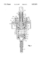
- FIG. 1 a section through an entire pump of the invention
- FIG. 2 a detail of the outlet valve showing the profiles of its cup-shaped seat and the lip of its valve member
- FIG. 3 a detail of a variant of the outlet valve.
- the pump of FIG. 1 has a body 1 provided with a bottom intake provided with an intake tube 11 and controlled by an inlet valve, having a ball 12 as its valve member, which ball is held captive by a cage 13 with internal stops 14, and by a top seat 15 having radial grooves.
- the piston is constituted by a bushing 2 assembled onto a hollow stem 3.
- the side wall of the bushing 2 seals against the pump body via two flexible lips 21 which are directed in opposite directions, and its base 22 which is pierced by an axial orifice 23 forms an annular seat 24 on its top surface, this seat being cup-shaped with a flared ring.
- the hollow stem 3 carries a collar 30 which, in the example shown, is formed of two concentric flanges 31 and 32 which are separated by a groove which receives the top edge 25 of the bushing.
- This stem forms a nozzle with an internal shoulder 33, its top end tapering externally to a standard diameter which allows engagement with a push-button of current type (not shown), generally provided with a spray nozzle.
- the base 22 defines an outlet valve chamber 26 which receives an outlet valve 4 which is bell-shaped with a downwardly-turned sealing distal lip 40.
- a return spring 41 placed from below in the internal channel of the stem or nozzle 3 bears against its shoulder 33 and presses the bell 40 against a valve seating bottom of the cup 24 situated on the top surface of the base 22 and which forms the lower portion of chamber 26.
- a spring 5 compressed between two opposed seats on the cage 13 and the bushing 2, returns the piston back upwards.
- a skirt 6 confines this entire mechanism within the body of the pump and allows the nozzle 3 to pass through. In FIG. 1, this is done by means of a metal washer crimped onto the rim 16 of the body; the washer is then crimped a second time by the packager, its gasket 61 being tightly pinched against a flask (not shown) containing the substance.
- the spring 5 presses the piston against the skirt 6; in the example shown, the internal clearance left by the gasket 61 and the grooves 17 in the rim 16 of the body 1 form a vent between the receptacle and the outside atmosphere along the nozzle 3; it is the shoulder formed by the collar 30 of the nozzle which sealingly engages against a gasket 62; operating the push-button opens communication therealong so as to put the pressure back into equilibrium.
- valve member has two opposed axial spindles which make it easier to mount.
- the top spindle 42 reduces the dead volumes and guides the spring 41; at its root, a seat 43 supports the spring, this seat preferably being grooved so as also to facilitate passage of the substance; the seat may act as a stop.
- the bottom spindle 44 At the bottom end of the stroke of the piston, just before the base 22, the bottom spindle 44 abuts the seat 15 of the cage 13 in conventional manner so as to force the valve member 4 to open to facilitate priming on first use, return of the piston to its rest position then causing the substance to be drawn in once the spring 41, now released again, has re-closed the outlet.
- FIG. 2 The structure of the outlet valve is seen more clearly in FIG. 2 which, enlarged to seventy times life size, allows its operation to be understood.
- valve seating cup 24 On the base 22 of bushing 2, around the orifice 23 of diameter 1.6 mm, valve seating cup 24 defines a bottom having a narrow annular radial valve seat surface 27 and a sidewall including a fillet 28 of radius 0.2 mm defining a torus having an average diameter of 2 mm connected with an outwardly sloping or flared ring 29, the outline of which is in the form of an arc of a circle having a height 0.4 mm. The slope of this ring increases from 0.25 at the bottom to about 0.7 at the top.
- the distal lip 40 of the valve member 4 terminates in a semi-circular distal crest having a radius of 0.15 mm and defining a torus having an average diameter of 2.1 mm which in the released or relaxed state, touches a portion of the flared ring, with the center line in the position A as shown represented by a solid line.
- the lip is compressed into a bottom position against the bottom of the cup as shown at B (as a broken line with long fine dashes), and lightly pressed into the sloping sidewall of the cup.
- the pump is operated, the increase in pressure under the valve member forces it outwardly against the cup sidewall, into a position C (represented as a broken line with long thick dashes), slightly offset towards the outside.
- the lip 40 then lifts off the sidewall so that the valve allows the flow to pass; given the small size of the dead volumes, the fall in pressure reaches an equilibrium between the orifice which it has just opened and that of the spray nozzle, so that the lip contracts again and the valve member falls back down to an equilibrium position E (represented by a dotted line) leaving a narrow throat opposite the sidewall ring 29, the flow converging towards the throat and then progressively diverging.
- the valve remains open under the force of the spindle 44 and does not return to the position B until the user releases the applied force.
- the trajectory within the cup 24 is a cycle which is represented by dotted line F.
- FIG. 3 shows an example of an acceptable variant, in which the cup ring 29 has a constant slope of 0.3 mm and the seating 27 has a conical shape approaching orifice 23 which increases the contact surface at rest, this being compensated by a reduced inside angle on the edge of the lip 40. This gives a slightly higher valve lift but also allows a gentle operation and a very steady spraying.
Landscapes
- Reciprocating Pumps (AREA)
- Containers And Packaging Bodies Having A Special Means To Remove Contents (AREA)
- Pharmaceuticals Containing Other Organic And Inorganic Compounds (AREA)
- Display Devices Of Pinball Game Machines (AREA)
- Rotary Pumps (AREA)
- Closures For Containers (AREA)
Applications Claiming Priority (2)
| Application Number | Priority Date | Filing Date | Title |
|---|---|---|---|
| FR9412460 | 1994-10-19 | ||
| FR9412460A FR2726045B1 (fr) | 1994-10-19 | 1994-10-19 | Pompe miniature a precompression |
Publications (1)
| Publication Number | Publication Date |
|---|---|
| US5671874A true US5671874A (en) | 1997-09-30 |
Family
ID=9467987
Family Applications (1)
| Application Number | Title | Priority Date | Filing Date |
|---|---|---|---|
| US08/544,717 Expired - Lifetime US5671874A (en) | 1994-10-19 | 1995-10-18 | Miniature dispenser pump and outlet valve for same |
Country Status (10)
| Country | Link |
|---|---|
| US (1) | US5671874A (da) |
| EP (1) | EP0707894B1 (da) |
| AT (1) | ATE195440T1 (da) |
| CA (1) | CA2160826C (da) |
| DE (1) | DE69518379T2 (da) |
| DK (1) | DK0707894T3 (da) |
| ES (1) | ES2151035T3 (da) |
| FR (1) | FR2726045B1 (da) |
| PT (1) | PT707894E (da) |
| SI (1) | SI0707894T1 (da) |
Cited By (14)
| Publication number | Priority date | Publication date | Assignee | Title |
|---|---|---|---|---|
| WO2000024652A1 (en) * | 1998-10-28 | 2000-05-04 | Emson, Inc. | Double spring precompression pump with priming feature |
| US6371337B2 (en) * | 2000-03-20 | 2002-04-16 | Valois S.A. | Dispensing member having an outlet valve formed by a differential piston |
| US20030197033A1 (en) * | 2002-04-17 | 2003-10-23 | Valois S.A. | Fluid dispenser pump |
| US20040035887A1 (en) * | 2002-06-14 | 2004-02-26 | Valois Sas | Fixing member, and a fluid dispenser including such a fixing member |
| DE102010045059A1 (de) * | 2010-09-10 | 2012-03-15 | F. Holzer Gmbh | Dosiervorrichtung |
| DE102010048986A1 (de) * | 2010-10-20 | 2012-04-26 | Ursapharm Arzneimittel Gmbh | Dosierpumpe |
| US8287495B2 (en) | 2009-07-30 | 2012-10-16 | Tandem Diabetes Care, Inc. | Infusion pump system with disposable cartridge having pressure venting and pressure feedback |
| US8408421B2 (en) | 2008-09-16 | 2013-04-02 | Tandem Diabetes Care, Inc. | Flow regulating stopcocks and related methods |
| US8650937B2 (en) | 2008-09-19 | 2014-02-18 | Tandem Diabetes Care, Inc. | Solute concentration measurement device and related methods |
| US20140217124A1 (en) * | 2011-09-20 | 2014-08-07 | Yonwoo Co., Ltd. | Spray pump |
| US8986253B2 (en) | 2008-01-25 | 2015-03-24 | Tandem Diabetes Care, Inc. | Two chamber pumps and related methods |
| CN106837774A (zh) * | 2016-12-26 | 2017-06-13 | 卢小平 | 一种微型活塞泵 |
| US9962486B2 (en) | 2013-03-14 | 2018-05-08 | Tandem Diabetes Care, Inc. | System and method for detecting occlusions in an infusion pump |
| US10258736B2 (en) | 2012-05-17 | 2019-04-16 | Tandem Diabetes Care, Inc. | Systems including vial adapter for fluid transfer |
Families Citing this family (3)
| Publication number | Priority date | Publication date | Assignee | Title |
|---|---|---|---|---|
| AU2891497A (en) * | 1996-09-20 | 1998-04-14 | Fritz Meckenstock | Outlet valve, especially for a hand pump, and the pump |
| DE29717034U1 (de) | 1997-09-23 | 1999-01-28 | Josef Wischerath Gmbh & Co. Kg, 50259 Pulheim | Spenderpumpe, Spender und Spender-Baukastensystem |
| FR2878002B1 (fr) * | 2004-11-16 | 2011-01-21 | Valois Sas | Pompe de distribution de produit fluide et distributeur comportant une telle pompe de distribution. |
Citations (8)
| Publication number | Priority date | Publication date | Assignee | Title |
|---|---|---|---|---|
| US3257961A (en) * | 1964-04-23 | 1966-06-28 | Holmes T J Co | Pump |
| US3583605A (en) * | 1969-01-17 | 1971-06-08 | Diamond Int Corp | Liquid dispensing pump |
| US4154374A (en) * | 1977-10-03 | 1979-05-15 | Ethyl Products Company | Finger operated spray pump |
| US4252507A (en) * | 1979-09-10 | 1981-02-24 | Seaquist Valve Company | Hand-actuatable pump assembly |
| US4434916A (en) * | 1981-01-07 | 1984-03-06 | S.A.R. S.P.A. | Manually operated liquid dispensing pump |
| US4607765A (en) * | 1984-04-19 | 1986-08-26 | S.A.R. S.P.A. | Manually operated pump for the delivery under pressure of liquid substances |
| US4941595A (en) * | 1988-10-10 | 1990-07-17 | Monturas A.S. | Spray pump |
| EP0536617A1 (en) * | 1991-10-11 | 1993-04-14 | EXO S.r.l. | Manually operated pump for dispensing liquid or creamy substances at a predetermined constant pressure |
-
1994
- 1994-10-19 FR FR9412460A patent/FR2726045B1/fr not_active Expired - Fee Related
-
1995
- 1995-10-13 ES ES95402284T patent/ES2151035T3/es not_active Expired - Lifetime
- 1995-10-13 SI SI9530453T patent/SI0707894T1/xx unknown
- 1995-10-13 EP EP95402284A patent/EP0707894B1/fr not_active Expired - Lifetime
- 1995-10-13 PT PT95402284T patent/PT707894E/pt unknown
- 1995-10-13 DK DK95402284T patent/DK0707894T3/da active
- 1995-10-13 AT AT95402284T patent/ATE195440T1/de not_active IP Right Cessation
- 1995-10-13 DE DE69518379T patent/DE69518379T2/de not_active Expired - Fee Related
- 1995-10-18 CA CA002160826A patent/CA2160826C/en not_active Expired - Fee Related
- 1995-10-18 US US08/544,717 patent/US5671874A/en not_active Expired - Lifetime
Patent Citations (8)
| Publication number | Priority date | Publication date | Assignee | Title |
|---|---|---|---|---|
| US3257961A (en) * | 1964-04-23 | 1966-06-28 | Holmes T J Co | Pump |
| US3583605A (en) * | 1969-01-17 | 1971-06-08 | Diamond Int Corp | Liquid dispensing pump |
| US4154374A (en) * | 1977-10-03 | 1979-05-15 | Ethyl Products Company | Finger operated spray pump |
| US4252507A (en) * | 1979-09-10 | 1981-02-24 | Seaquist Valve Company | Hand-actuatable pump assembly |
| US4434916A (en) * | 1981-01-07 | 1984-03-06 | S.A.R. S.P.A. | Manually operated liquid dispensing pump |
| US4607765A (en) * | 1984-04-19 | 1986-08-26 | S.A.R. S.P.A. | Manually operated pump for the delivery under pressure of liquid substances |
| US4941595A (en) * | 1988-10-10 | 1990-07-17 | Monturas A.S. | Spray pump |
| EP0536617A1 (en) * | 1991-10-11 | 1993-04-14 | EXO S.r.l. | Manually operated pump for dispensing liquid or creamy substances at a predetermined constant pressure |
Cited By (31)
| Publication number | Priority date | Publication date | Assignee | Title |
|---|---|---|---|---|
| US6170713B1 (en) * | 1998-10-28 | 2001-01-09 | Emson, Inc. | Double spring precompression pump with priming feature |
| AU763918B2 (en) * | 1998-10-28 | 2003-08-07 | Emsar, Inc. | Double spring precompression pump with priming feature |
| RU2243146C2 (ru) * | 1998-10-28 | 2004-12-27 | Эмсар, Инк. | Двухпружинный насос предварительного сжатия с признаком заливки |
| WO2000024652A1 (en) * | 1998-10-28 | 2000-05-04 | Emson, Inc. | Double spring precompression pump with priming feature |
| US6371337B2 (en) * | 2000-03-20 | 2002-04-16 | Valois S.A. | Dispensing member having an outlet valve formed by a differential piston |
| US20030197033A1 (en) * | 2002-04-17 | 2003-10-23 | Valois S.A. | Fluid dispenser pump |
| US6929156B2 (en) * | 2002-04-17 | 2005-08-16 | Valois Sas | Fluid dispenser pump |
| US20040035887A1 (en) * | 2002-06-14 | 2004-02-26 | Valois Sas | Fixing member, and a fluid dispenser including such a fixing member |
| US8986253B2 (en) | 2008-01-25 | 2015-03-24 | Tandem Diabetes Care, Inc. | Two chamber pumps and related methods |
| US8408421B2 (en) | 2008-09-16 | 2013-04-02 | Tandem Diabetes Care, Inc. | Flow regulating stopcocks and related methods |
| US8448824B2 (en) | 2008-09-16 | 2013-05-28 | Tandem Diabetes Care, Inc. | Slideable flow metering devices and related methods |
| US8650937B2 (en) | 2008-09-19 | 2014-02-18 | Tandem Diabetes Care, Inc. | Solute concentration measurement device and related methods |
| US12539364B2 (en) | 2009-07-30 | 2026-02-03 | Tandem Diabetes Care, Inc. | Infusion pump systems with disposable cartridge having pressure venting and pressure feedback |
| US8287495B2 (en) | 2009-07-30 | 2012-10-16 | Tandem Diabetes Care, Inc. | Infusion pump system with disposable cartridge having pressure venting and pressure feedback |
| US8758323B2 (en) | 2009-07-30 | 2014-06-24 | Tandem Diabetes Care, Inc. | Infusion pump system with disposable cartridge having pressure venting and pressure feedback |
| US8298184B2 (en) | 2009-07-30 | 2012-10-30 | Tandem Diabetes Care, Inc. | Infusion pump system with disposable cartridge having pressure venting and pressure feedback |
| US8926561B2 (en) | 2009-07-30 | 2015-01-06 | Tandem Diabetes Care, Inc. | Infusion pump system with disposable cartridge having pressure venting and pressure feedback |
| US9211377B2 (en) | 2009-07-30 | 2015-12-15 | Tandem Diabetes Care, Inc. | Infusion pump system with disposable cartridge having pressure venting and pressure feedback |
| US11135362B2 (en) | 2009-07-30 | 2021-10-05 | Tandem Diabetes Care, Inc. | Infusion pump systems and methods |
| US12144964B2 (en) | 2009-07-30 | 2024-11-19 | Tandem Diabetes Care, Inc | Infusion pump system with disposable cartridge having pressure venting and pressure feedback |
| US12042627B2 (en) | 2009-07-30 | 2024-07-23 | Tandem Diabetes Care, Inc. | Infusion pump systems and methods |
| US11285263B2 (en) | 2009-07-30 | 2022-03-29 | Tandem Diabetes Care, Inc. | Infusion pump systems and methods |
| DE102010045059A1 (de) * | 2010-09-10 | 2012-03-15 | F. Holzer Gmbh | Dosiervorrichtung |
| US9415925B2 (en) | 2010-09-10 | 2016-08-16 | F. Holzer Gmbh | Metering device |
| DE102010048986A1 (de) * | 2010-10-20 | 2012-04-26 | Ursapharm Arzneimittel Gmbh | Dosierpumpe |
| US20140217124A1 (en) * | 2011-09-20 | 2014-08-07 | Yonwoo Co., Ltd. | Spray pump |
| US9566596B2 (en) * | 2011-09-20 | 2017-02-14 | Yonwoo Co., Ltd. | Spray pump |
| US10258736B2 (en) | 2012-05-17 | 2019-04-16 | Tandem Diabetes Care, Inc. | Systems including vial adapter for fluid transfer |
| US9962486B2 (en) | 2013-03-14 | 2018-05-08 | Tandem Diabetes Care, Inc. | System and method for detecting occlusions in an infusion pump |
| CN106837774B (zh) * | 2016-12-26 | 2019-05-14 | 卢小平 | 一种微型活塞泵 |
| CN106837774A (zh) * | 2016-12-26 | 2017-06-13 | 卢小平 | 一种微型活塞泵 |
Also Published As
| Publication number | Publication date |
|---|---|
| FR2726045B1 (fr) | 1997-01-10 |
| EP0707894B1 (fr) | 2000-08-16 |
| FR2726045A1 (fr) | 1996-04-26 |
| ATE195440T1 (de) | 2000-09-15 |
| CA2160826A1 (en) | 1996-04-20 |
| EP0707894A1 (fr) | 1996-04-24 |
| ES2151035T3 (es) | 2000-12-16 |
| DE69518379T2 (de) | 2001-03-15 |
| DE69518379D1 (de) | 2000-09-21 |
| DK0707894T3 (da) | 2001-01-02 |
| PT707894E (pt) | 2001-02-28 |
| SI0707894T1 (en) | 2001-02-28 |
| CA2160826C (en) | 2008-03-11 |
Similar Documents
| Publication | Publication Date | Title |
|---|---|---|
| US5671874A (en) | Miniature dispenser pump and outlet valve for same | |
| US5803318A (en) | Precompression pump | |
| US4606479A (en) | Pump for dispensing liquid from a container | |
| US4986453A (en) | Atomizing pump | |
| KR100346034B1 (ko) | 액체용 수동 분무 장치 | |
| JP3679977B2 (ja) | トリガー作動ポンプ式噴霧器およびその排出弁アセンブリー | |
| US4274560A (en) | Atomizing pump dispenser | |
| US4113145A (en) | Dispensing unit for liquid and method of dispensing | |
| US4173297A (en) | Non-throttling manually reciprocated plunger pump for consumer-type liquid dispensing containers | |
| US5301852A (en) | Manually operated pump for dispensing liquid or creamy substances at a predetermined constant pressure | |
| US5289952A (en) | Device for dispensing foam, and push-button for a device of this kind | |
| US4155489A (en) | Leakproof pump for hand-held dispensers | |
| US3724726A (en) | Pump for spraying | |
| US4640443A (en) | Manually operated dispensing pump | |
| CZ107496A3 (en) | Pumping atomizer | |
| US4389003A (en) | Sliding inlet seal for an atomizing pump dispenser | |
| US6974055B2 (en) | Adapter for a manually operated dispensing device of containers of liquid | |
| US4692103A (en) | Precise output pump sprayer | |
| JPH04267962A (ja) | 出口通路内にある流体製品を作動の終期に吸入する流体製品噴霧または分与装置 | |
| US4087025A (en) | Leakproof pump for hand-held dispensers | |
| US4494680A (en) | Manually operated dispensing pump | |
| US4053086A (en) | Pumps for hand-held dispensers | |
| US5108013A (en) | Pump for dispensing liquid from a container | |
| JP3510862B2 (ja) | バネ形成ダイヤフラム及びそれに取付ける容器を備えたポンプ | |
| JP2000153190A (ja) | ポンプ |
Legal Events
| Date | Code | Title | Description |
|---|---|---|---|
| AS | Assignment |
Owner name: SOFAB, FRANCE Free format text: ASSIGNMENT OF ASSIGNORS INTEREST;ASSIGNORS:BEHAR, ALAIN;EUDES, MARCEL;REEL/FRAME:007903/0982 Effective date: 19951201 |
|
| STCF | Information on status: patent grant |
Free format text: PATENTED CASE |
|
| FEPP | Fee payment procedure |
Free format text: PAYOR NUMBER ASSIGNED (ORIGINAL EVENT CODE: ASPN); ENTITY STATUS OF PATENT OWNER: LARGE ENTITY |
|
| FPAY | Fee payment |
Year of fee payment: 4 |
|
| FEPP | Fee payment procedure |
Free format text: PAYOR NUMBER ASSIGNED (ORIGINAL EVENT CODE: ASPN); ENTITY STATUS OF PATENT OWNER: LARGE ENTITY Free format text: PAYER NUMBER DE-ASSIGNED (ORIGINAL EVENT CODE: RMPN); ENTITY STATUS OF PATENT OWNER: LARGE ENTITY |
|
| FPAY | Fee payment |
Year of fee payment: 8 |
|
| FPAY | Fee payment |
Year of fee payment: 12 |
|
| AS | Assignment |
Owner name: ALBEA LE TREPORT S.A.S, FRANCE Free format text: CHANGE OF NAME;ASSIGNOR:REXAM DISPENSING SYSTEMS S.A.S.;REEL/FRAME:033088/0538 Effective date: 20130502 |